Duet3D Logo Duet3D
    • Tags
    • Documentation
    • Order
    • Register
    • Login

    duet 3 connecting z probe inductive sensor

    Scheduled Pinned Locked Moved Solved
    Duet Hardware and wiring
    4
    25
    1.5k
    Loading More Posts
    • Oldest to Newest
    • Newest to Oldest
    • Most Votes
    Reply
    • Reply as topic
    Log in to reply
    This topic has been deleted. Only users with topic management privileges can see it.
    • Phaedruxundefined
      Phaedrux Moderator
      last edited by

      Your photo did not upload.

      Z-Bot CoreXY Build | Thingiverse Profile

      1 Reply Last reply Reply Quote 0
      • aprzundefined
        aprz
        last edited by

        yeah never mind the picture, it was just the diagram of the duet 3 board. but im just lost on why its showing that error message?

        2020-08-20-053526_1920x1080_scrot.png

        1 Reply Last reply Reply Quote 0
        • Phaedruxundefined
          Phaedrux Moderator
          last edited by

          Post your config please. It probably means that you need to invert the pin.

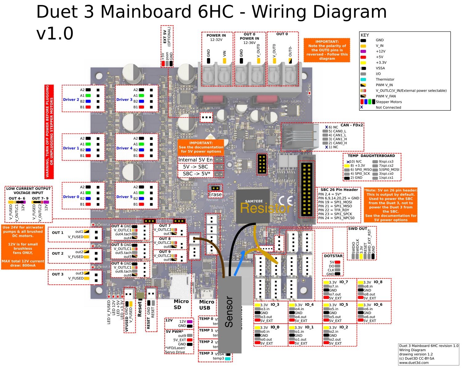
          From the link I posted

          Duet 3, you can connect the output of the sensor directly to the Z-probe IN pin. Connect the sensor ground wire to a ground pin on the Duet, and the sensor's + power wire to a suitable voltage (typically to VIN because these sensors usually need between 6 and 30V power).
          Select mode 5 (P5) in the M558 command, also include parameter I1 in the M558 command.

          In the case of RRF3 the I1 to invert has been replaced by adding a ! in front of the pin name in the M558.

          Z-Bot CoreXY Build | Thingiverse Profile

          1 Reply Last reply Reply Quote 0
          • aprzundefined
            aprz
            last edited by aprz

            
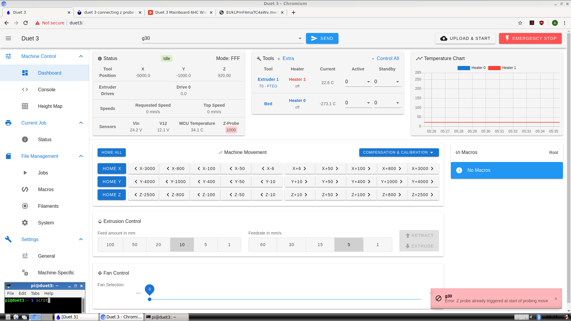
            ; Z-Probe
            M558 P5 C"!^io5.in" H5 F120 T6000                   ; set Z probe type to switch and the dive height + speeds
            G31 P500 X41 Y41 Z2.5                              ; set Z probe trigger value, offset and trigger height
            M557 X15:215 Y15:195 S20                           ; define mesh grid


            So, I added the "!" before the name of the pin Im using as you said to do and its now showing the value for the z probe as 0 now. but I send g30 and to test whether it would sense anything, I put a piece of aluminium against the sensor and it doesn't change the value to 1000 or show that its sensed anything below it. Im not sure why. The z axis is moving slowly down after sending g30 but it should stop and the value of the z probe reading on RRP should be 1000 if it senses anything, right?

            2020-08-20-183023_1920x1080_scrot.png

            1 Reply Last reply Reply Quote 0
            • Phaedruxundefined
              Phaedrux Moderator
              last edited by

              @1997alex said in duet 3 connecting z probe inductive sensor:

              C"!^io5.in"

              Try removing the ^ to disable the pull up resistor.

              Z-Bot CoreXY Build | Thingiverse Profile

              aprzundefined 1 Reply Last reply Reply Quote 0
              • aprzundefined
                aprz @Phaedrux
                last edited by

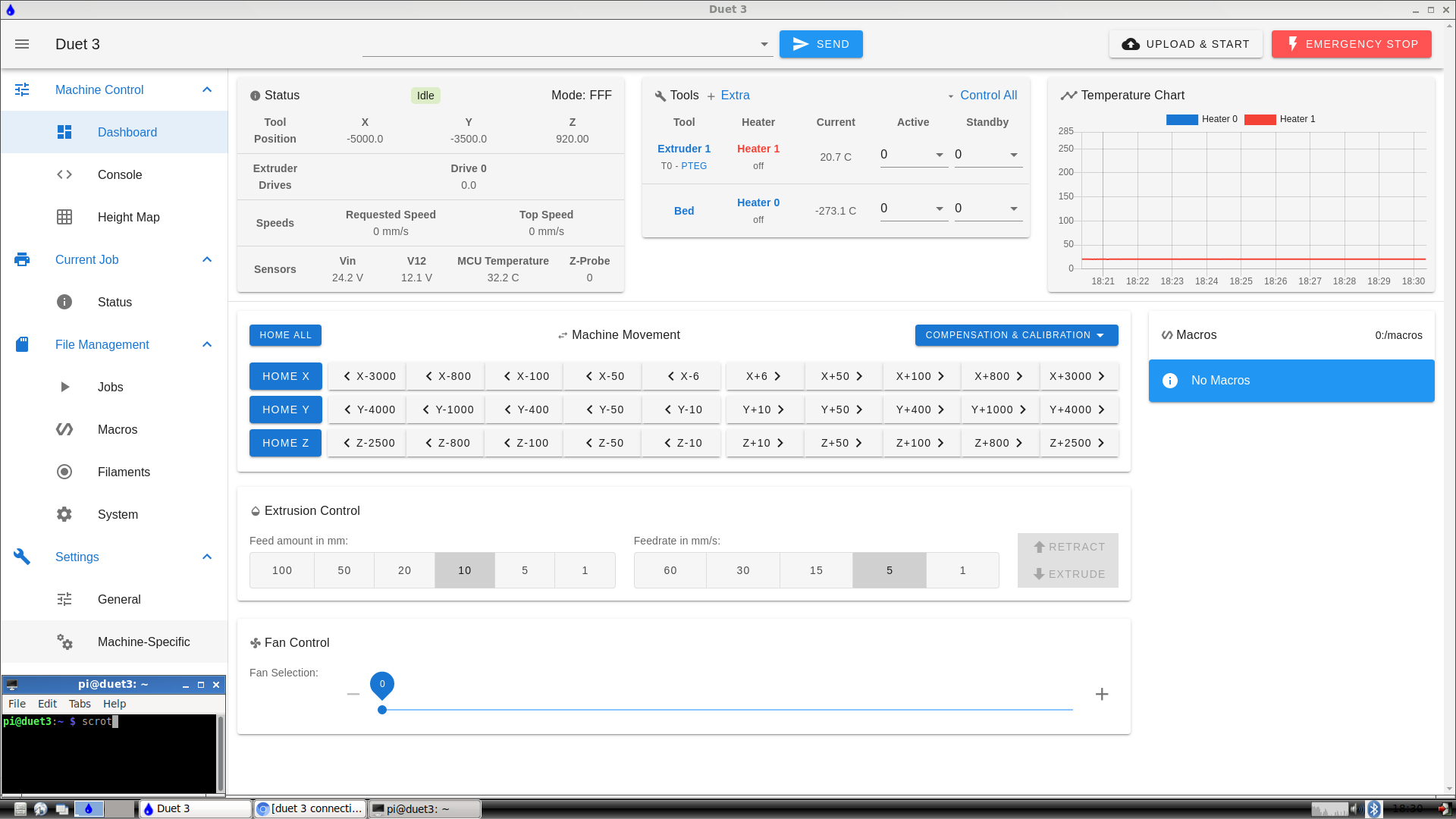
                @Phaedrux ok, just removed the “^” from in front. Still nothing. Just to clarify, it’s supposed to show 0 under “z probe” when it’s not sensing and 1000 when it is, right? Not sure if it’s my code still or wiring ? I have it wired from the 3.3v to the ground and io5in.

                1 Reply Last reply Reply Quote 0
                • Phaedruxundefined
                  Phaedrux Moderator
                  last edited by

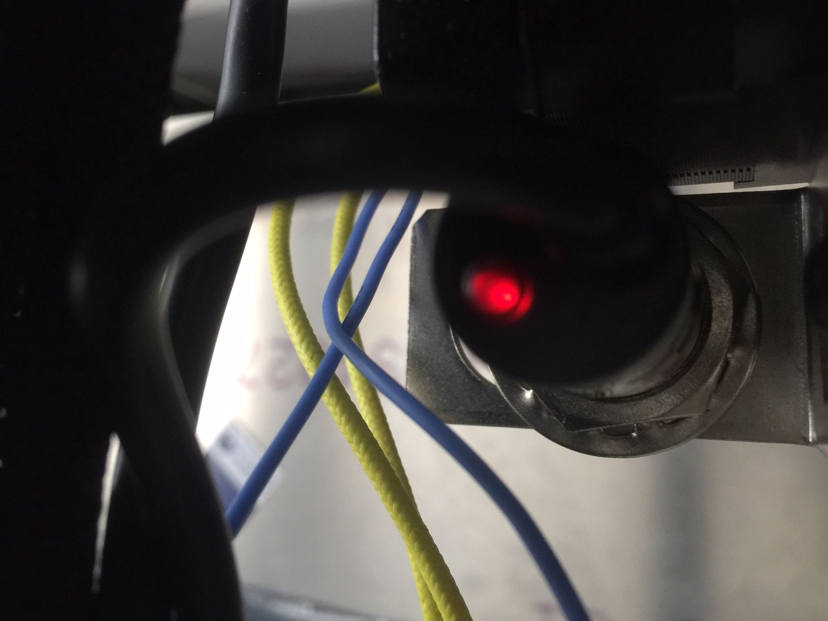
                  Can you post a photo of how it's wired up?
                  Does it have it's own indicator light showing when it's triggering?

                  Z-Bot CoreXY Build | Thingiverse Profile

                  aprzundefined 1 Reply Last reply Reply Quote 0
                  • aprzundefined
                    aprz @Phaedrux
                    last edited by

                    @Phaedrux

                    ; Z-Probe
                    M558 P5 C"!io5.in" H5 F120 T6000                   ; set Z probe type to switch and the dive height + speeds
                    G31 P500 X41 Y41 Z2.5                              ; set Z probe trigger value, offset and trigger height
                    M557 X15:215 Y15:195 S20                           ; define mesh grid


                    2020-09-03-224527_1920x1080_scrot.png

                    IMG_1722.jpg

                    IMG_1723.JPG

                    1 Reply Last reply Reply Quote 0
                    • aprzundefined
                      aprz
                      last edited by

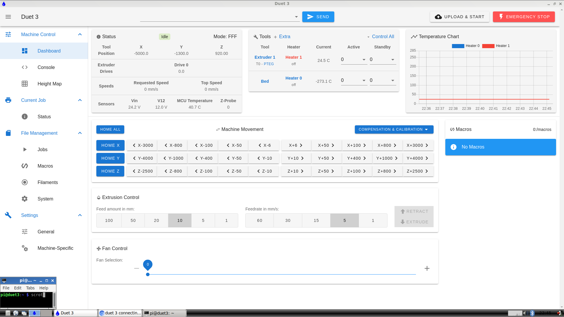
                      So, the light turns on when I put a metal object under the sensor but doesn't indicate whether its on in the RRF dashboard . The value stays at 0 under "z probe".

                      1 Reply Last reply Reply Quote 0
                      • Phaedruxundefined
                        Phaedrux Moderator
                        last edited by

                        I suspect a bad signal wire from your probe.

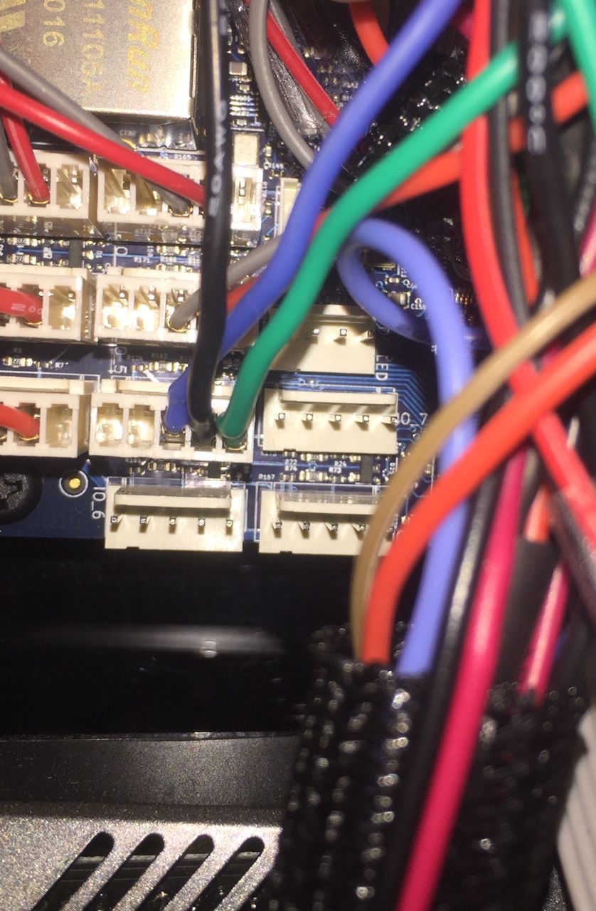
                        In your photo, which wire is which?

                        Z-Bot CoreXY Build | Thingiverse Profile

                        1 Reply Last reply Reply Quote 0
                        • aprzundefined
                          aprz
                          last edited by aprz

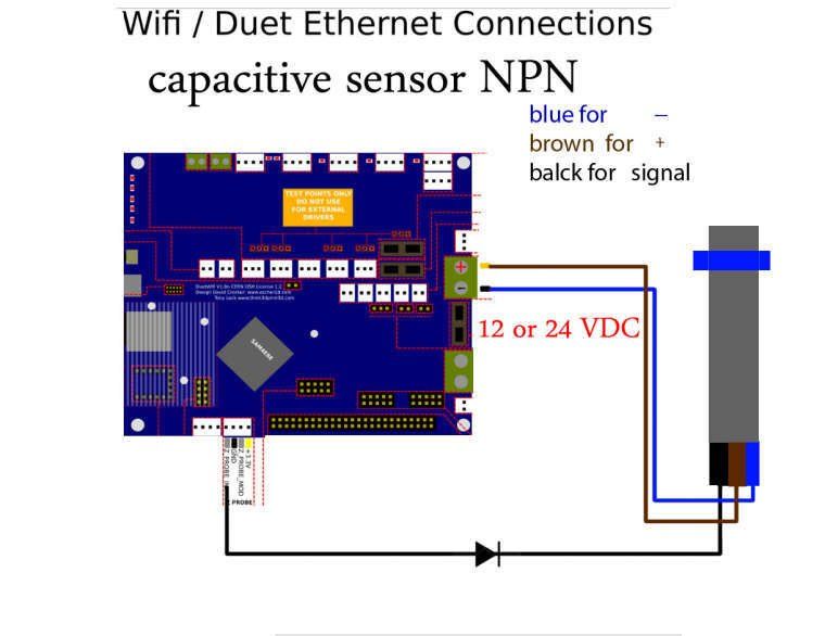
                          the green (actually brown) is the positive, the black is the sensor, and the blue is negative. i may be wrong. reference diagram.
                          ogA64gS3SXCmPhsQ.jpg

                          1 Reply Last reply Reply Quote 0
                          • Phaedruxundefined
                            Phaedrux Moderator
                            last edited by

                            You have the brown/green wire connected to the 3.3v for power.

                            The diagram shows the probe being connected to 12/24v vin.

                            Does your probe function at 3.3v or does it need more?

                            Z-Bot CoreXY Build | Thingiverse Profile

                            aprzundefined 1 Reply Last reply Reply Quote 0
                            • aprzundefined
                              aprz @Phaedrux
                              last edited by

                              @Phaedrux I just connected it to vin 24v but still see no difference in the z probe value.

                              1 Reply Last reply Reply Quote 0
                              • Phaedruxundefined
                                Phaedrux Moderator
                                last edited by

                                Do you have a link to information on what probe it actually is?

                                Z-Bot CoreXY Build | Thingiverse Profile

                                aprzundefined 1 Reply Last reply Reply Quote 0
                                • aprzundefined
                                  aprz @Phaedrux
                                  last edited by aprz

                                  @Phaedrux This is the exact one. looks like the pnp style sensors require a resistor?

                                  https://www.amazon.com/Twidec-Inductive-Proximity-Detecting-LJ18A3-8-Z/dp/B07WS45K3P/ref=sr_1_1?dchild=1&keywords=b07ws45k3p&qid=1599193793&sr=8-1

                                  Phaedruxundefined 1 Reply Last reply Reply Quote 0
                                  • Vetiundefined
                                    Veti
                                    last edited by Veti

                                    can you show us your new wiring

                                    aprzundefined 1 Reply Last reply Reply Quote 0
                                    • aprzundefined
                                      aprz @Veti
                                      last edited by aprz

                                      @Veti Here it is. Picture 1 shows the signal wire connected to io5.in and picture 2 shows the positive and negative wires in 12v supply.

                                      8F35663A-DB96-410E-AB41-A392A2A1ED8B.jpeg 9DEAE847-AC3A-45BA-BEFA-5D682EE716C3.jpeg

                                      1 Reply Last reply Reply Quote 0
                                      • Phaedruxundefined
                                        Phaedrux Moderator @aprz
                                        last edited by

                                        @1997alex said in duet 3 connecting z probe inductive sensor:

                                        @Phaedrux This is the exact one. looks like the pnp style sensors require a resistor?

                                        https://www.amazon.com/Twidec-Inductive-Proximity-Detecting-LJ18A3-8-Z/dp/B07WS45K3P/ref=sr_1_1?dchild=1&keywords=b07ws45k3p&qid=1599193793&sr=8-1

                                        Ok, so it's a PNP NO sensor not NPN.

                                        https://duet3d.dozuki.com/Wiki/Connecting_a_Z_probe#Section_PNP_output_normally_open_inductive_or_capacitive_sensor

                                        See if this makes a difference.

                                        Z-Bot CoreXY Build | Thingiverse Profile

                                        1 Reply Last reply Reply Quote 0
                                        • aprzundefined
                                          aprz
                                          last edited by aprz

                                          Ok,I ordered a few 10k, 30k and 68k resistors. I’ll follow up on how it comes out or whether it works. Here’s a drawing of how I’m understanding from the article how to connect the resistor to the duet and sensor. If this doesn’t work I’ll just buy a npn sensor. The yellow lines are the two resistors tied together and connected to ground and sensor wire.by the way the positive is going to be connected to 12v pin. Correct me if I’m wrong or a potential .
                                          DE740FD6-62A9-42E7-ABA7-235AF5C10E5F.jpeg

                                          1 Reply Last reply Reply Quote 0
                                          • aprzundefined
                                            aprz
                                            last edited by aprz

                                            Ok never mind the resistors, I’ll try that out later but I just ordered another probe that is a npn swapped it out. It works just had to fix a couple wiring issues but anyone out there wanting to use a inductive sensor make sure it’s a npn inductive sensor, also the sensor works with the 3.3v power in the io5 pin and didn’t need to wire it to the vin or 12v. I have the brown going to 3.3v, the blue going to ground and the black going to “io5.in”. Well thanks for the help problem solved.👍

                                            1 Reply Last reply Reply Quote 1
                                            • First post
                                              Last post
                                            Unless otherwise noted, all forum content is licensed under CC-BY-SA