How to Control Speed of Small AC Motor
-
A digital pot certainly would work as a replacement for the manual pot, but you can't control a digital pot with a PWM signal.
It neds to have specific command sent to it to configure it and adjust it's settings.
-
@alankilian Darn... and I can't find any PWM-controlled potentiometers. Doesn't seem like that's a common use case. I guess I could do a hobby servo to turn the knob. It's not my favorite solution, but I think it would work out pretty well. Do you have any recommendation?
-
How far do you need to turn the knob to get the range of pressures you want?
Most hobby servos can turn 180-degrees.
Most potentiometers turn more than that, so if you can find a 180-degree range of potentiometer angles, you can just bolt on a hobby servo.
Luckily, you have a 3D printer and can just print something up!Then, how do you want to control it from Duet?
GCODE from your slicer or something more automatic? -
@alankilian 270 degrees from completely off, but there's only 180 degrees of actual speed adjustment
It's my part cooling fan. I've been having a lot of trouble with part cooling when printing above 250mm/s. Accuracy is spot-on, but the heat buildup in the part is causing things to get badly warped after a few minutes. My current 6w pump isn't adequate (brushless 24v, runs right from a fan header), so I'm hoping this 20w pump will be more adequate. It certainly spews forth a ton of air.
I've got some old Traxxas steering boxes laying around, though I don't think they can handle much more than 6v. Ideally I could just hook a servo right up to the same 24v fan header and have it behave the same as the old pump. Though I could switch to one of the 5v outputs if absolutely necessary.
-
which board are you connecting it to?
-
@jay_s_uk Duet 3
-
@GoremanX said in How to Control Speed of Small AC Motor:
Ideally I could just hook a servo right up to the same 24v fan header
You are going to have to hook the servo to some source of 5 Volt power and to a nonfan output pin.
THIS page shows how to hook up a hobby servo.
THIS page shows how to control the angle of a hobby servo.
-
@alankilian So if I'm understanding this right, I could power the servo directly from a separate 5v power supply (which I happen to already have in my printer), and then send the pwm signal from one of the IO headers, and not have to worry about protecting the board from damage with diodes?
I have a servo motor here with a 300 degree sweep. Can I set M950 to an io pin rather than an output, and then just have the motor turn from, say, 5 degrees to 295 degrees by just setting the fan speed the same way I would a normal fan? I could just mount the dimmer board to a spring so the entire thing twists when the servo goes beyond the range of the pot. Or is the PWM signal not the same in servo vs fan mode?
-
@GoremanX I have never used a servo, so I'm not going to really be able to help with the controls-side of things.
Don't the links I sent discuss how to control the angle of the servo from GCODE?
-
@alankilian Yeah but angular motion isn't how the firmware controls fan speed. If I want part cooling to work, it looks like the part cooling fan needs to be assigned with M950 and M106, and then assigned to the appropriate tool with M563. I don't know if a servo that was assigned with M42 can be assigned to M563. In any case, M42 basically does the same thing as M106, but with preset frequencies that are appropriate to servos. So it's possible I can just replicate that with M950 Q50
-
Wait... does it even matter what connector I use? Isn't the PWM signal on fan headers generated by the ground pin? Couldn't I just hook up the PWM signal wire of the servo motor to any fan output ground pin? I don't know if the io headers are evn PWM-capable...
-
No, you need a pin that can go high and low to signal the servo.
The fan outputs only go high-impedance to low.
So you COULD tie a resistor to +5 from the fan ground pin and use tht as a signal.
I don't know why that would help you control the servo though.
I just don't know enough about fan control to be able to help.Other than that, I don't know how fan-control can be mapped into servo-angle control.
Maybe searching on the forum will help you come up with something.
-
@alankilian ugh, I feel like the whole thing is getting too complicated. I might settle for just an on/off solution with the motor speed set manually with the knob. I already have a 110v AC outlet on my printer that's switched by the Duet board.
But it sure would be nice to somehow be able to control AC motor speed through the Duet board... I can think of a bunch of applications that would benefit from it, like spindle speed on a CNC router, this air pump setup, etc
-
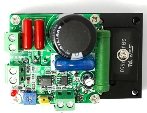
How about one of these?
https://www.amazon.com/dp/B00OSWQC9YLooks like it accepts a standard 12v PWM signal to control a 110v AC router spindle speed up to 10A
-
That's for controlling DC spindle motors.
- 12V 24V 48V 110V DC Motor Speed Controller
-
@alankilian It actually says both: "Can support AC and DC input"
And the printed text on the board says input can be AC or DC, while the PWM signal can be up to 12v DC
-
-
You can make up a circuit to control a triac from another device. Here is an example https://circuitspedia.com/remote-control-ac-dimmer-arduino/. It would need some adaptation to take a PWM input.
-
@GoremanX
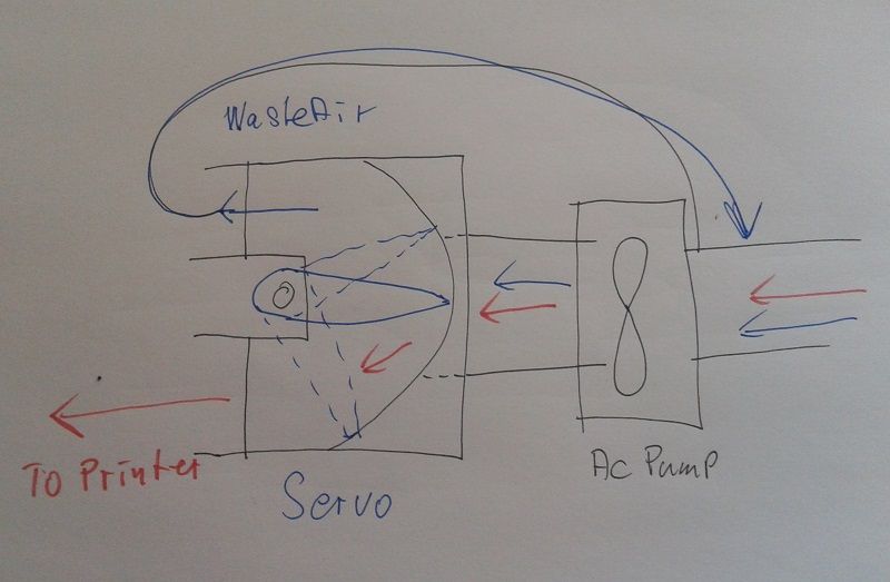
Why do you try to control the pumps RPM? The resulting airstream would be very non-linear.
Why not run the pump at full RPM ( maybe ON/OFF controlled by a Relais ) and control a waste gaste with a servo. That's much safer than trying to control AC!Just split the airtube and control the amount of air guided to the printer. That would result in a much faster response and the opening angle of the air-splitter is proportional to the air stream.
To safe energy, you can feed the wasted airstream back to the inlet.

Best of all: It's a printable thing!

-
@o_lampe That's a really interesting idea! I like it.
The main reason I want to control the pump's RPM is to minimize noise when full flow isn't needed. This pump puts out a ton of air, and full flow is only really required when printing very fast.
Also, for this particular pump, there is no single inlet. The air is drawn in through a wide foam filter into a large intake manifold, and there are 2 pump diaphragms inside that are on opposite sides of the motor. It's a pretty decent design that creates a very smooth airflow and makes vibrations nearly nonexistent.
But your idea would be really cool for splitting airflow between the hotends on my dual extruder printer...

