help with config.g
-
Hi,
Please do the following from the DWC console:
Execute M122 and post the results
Execute M98 P"config.g" and post the results
Thanks.
Frederick
-
@patterson6
have you included power to the out 0 power in? out0 won't work without that.These are the correct settings for a daughter board with PT100 assuming you are using input number 1
M308 S1 P"spi.cs1" Y"rtd-max31865" ; PT100 Temperature Sensor you can interpolate the motors at any steps on the duet 3 but going higher than x16 probably won't make much difference.
-
-
You were right with the out0 in. So i just bridged from the 24v. The bed works now. Thanks
-
The M308 didnt work. Its not really on input number 1. Nothing is. I just put that in the config when i was in editor. Its just plugged into temp daughterboard then the z-prob is on IO3.
-
Any idea for pin assignment on how to gcode it? My White led turns on fine when i do a M106. I just have to get the expansion board installed when it comes for the r,g,b. It will be plugged into those pinouts on the expansion board.
;******************** RGBW led strip on build area **********************
M950 F4 C"out9" ; create white led on mainboard pin out9
;M950 F5 C"out6" ; create red led on expansion pin out 6
;M950 F6 C"out7" ; create green led on expansion pin out 7
;M950 F7 C"out8" ; create blue led on expansion pin out 8 -
Thanks
-
-
@patterson6 said in help with config.g:
M665 R316 L616.42 B215 H989.4 ; Set delta radius, diagonal rod length, printable radius and homed height
M666 X0 Y0 Z0 ; put your endstop adjustments here, or let auto calibration find themthis is not the result of a delta calibration.
also your config does not have a M501.
So you have not run a pid tune. this will cause the observed errors on the bed. -
@patterson6 said in help with config.g:
The M308 didnt work. Its not really on input number 1. Nothing is. I just put that in the config when i was in editor. Its just plugged into temp daughterboard then the z-prob is on IO3.
P"spi.cs1"that specifies the temp daughterboard. they have 2 inputs, CS0 and CS1 so you will have to modify that line accordingly
-
@fcwilt m122
still having trouble with hotend
###########################################################
=== Diagnostics ===
RepRapFirmware for Duet 3 MB6HC version 3.2 running on Duet 3 MB6HC v1.01 or later (standalone mode)
Board ID: 08DJM-956L2-G43S8-6J9FD-3SJ6R-TB0AG
Used output buffers: 1 of 40 (12 max)
=== RTOS ===
Static ram: 149788
Dynamic ram: 92524 of which 160 recycled
Never used RAM 116360, free system stack 200 words
Tasks: NETWORK(ready,199) ETHERNET(blocked,109) HEAT(blocked,297) CanReceiv(blocked,927) CanSender(blocked,371) CanClock(blocked,354) TMC(blocked,53) MAIN(running,1123) IDLE(ready,19)
Owned mutexes:
=== Platform ===
Last reset 00:01:10 ago, cause: software
Last software reset at 2021-03-12 07:19, reason: User, GCodes spinning, available RAM 116360, slot 2
Software reset code 0x0003 HFSR 0x00000000 CFSR 0x00000000 ICSR 0x00400000 BFAR 0x00000000 SP 0x00000000 Task MAIN Freestk 0 n/a
Error status: 0x00
Aux0 errors 0,0,0
Aux1 errors 0,0,0
MCU temperature: min 28.8, current 29.5, max 29.7
Supply voltage: min 21.4, current 22.4, max 24.6, under voltage events: 0, over voltage events: 0, power good: yes
12V rail voltage: min 12.0, current 12.1, max 12.1, under voltage events: 0
Driver 0: position 971943, standstill, reads 1384, writes 14 timeouts 0, SG min/max 0/0
Driver 1: position 971943, standstill, reads 1384, writes 14 timeouts 0, SG min/max 0/0
Driver 2: position 971943, standstill, reads 1385, writes 14 timeouts 0, SG min/max 0/0
Driver 3: position 0, standstill, reads 1385, writes 14 timeouts 0, SG min/max 0/0
Driver 4: position 0, standstill, reads 1388, writes 11 timeouts 0, SG min/max 0/0
Driver 5: position 0, standstill, reads 1388, writes 11 timeouts 0, SG min/max 0/0
Date/time: 2021-03-12 07:20:19
Slowest loop: 4.14ms; fastest: 0.05ms
=== Storage ===
Free file entries: 10
SD card 0 detected, interface speed: 25.0MBytes/sec
SD card longest read time 2.3ms, write time 0.0ms, max retries 0
=== Move ===
DMs created 125, maxWait 0ms, bed compensation in use: none, comp offset 0.000
=== MainDDARing ===
Scheduled moves 0, completed moves 0, hiccups 0, stepErrors 0, LaErrors 0, Underruns [0, 0, 0], CDDA state -1
=== AuxDDARing ===
Scheduled moves 0, completed moves 0, hiccups 0, stepErrors 0, LaErrors 0, Underruns [0, 0, 0], CDDA state -1
=== Heat ===
Bed heaters = 2 -1 -1 -1 -1 -1 -1 -1 -1 -1 -1 -1, chamberHeaters = 1 -1 -1 -1
=== GCodes ===
Segments left: 0
Movement lock held by null
HTTP is idle in state(s) 0
Telnet is idle in state(s) 0
File is idle in state(s) 0
USB is idle in state(s) 0
Aux is idle in state(s) 0
Trigger is idle in state(s) 0
Queue is idle in state(s) 0
LCD is idle in state(s) 0
SBC is idle in state(s) 0
Daemon is idle in state(s) 0
Aux2 is idle in state(s) 0
Autopause is idle in state(s) 0
Code queue is empty.
=== Network ===
Slowest loop: 6.76ms; fastest: 0.02ms
Responder states: HTTP(0) HTTP(0) HTTP(0) HTTP(0) HTTP(0) HTTP(0) FTP(0) Telnet(0), 0 sessions Telnet(0), 0 sessions
HTTP sessions: 1 of 8- Ethernet -
State: active
Error counts: 0 0 1 0 0
Socket states: 5 2 2 2 2 0 0 0
=== CAN ===
Messages queued 281, send timeouts 631, received 0, lost 0, longest wait 0ms for reply type 0, free buffers 48
###############################################################
M98 P"config.g"
HTTP is enabled on port 80
FTP is disabled
TELNET is disabled
Warning: Sensor number 0 has not been defined
Tool 0 offsets: X0.00 Y0.00 Z0.00
- Ethernet -
-
tried both 0 and 1 no go...
;****************************************** Hotend ********************************************************************
M308 S1 P"spi.cs0" Y"rtd-max31865" ; configure sensor 0 as thermistor // Smart effector // pt 100 // on daugherboard
M950 H0 C"out1" T0 ; create nozzle heater output on out1 and map it to sensor 0
M307 H0 B0 S1.00 ; disable bang-bang mode for heater and set PWM limit
M143 H0 S380 ; set temperature limit for heater 0 to 380C -
@patterson6 said in help with config.g:
tried both 0 and 1 no go...
;****************************************** Hotend ********************************************************************
M308 S1 P"spi.cs0" Y"rtd-max31865" ; configure sensor 0 as thermistor // Smart effector // pt 100 // on daugherboard
M950 H0 C"out1" T0 ; create nozzle heater output on out1 and map it to sensor 0
M307 H0 B0 S1.00 ; disable bang-bang mode for heater and set PWM limit
M143 H0 S380 ; set temperature limit for heater 0 to 380Cyou should be using H1 rather H0 otherwise the heater won't be created correctly for the tool
-
@Veti what do you mean its not a result of a delta calibration? what am i missing? Where would the M501 go? Yeah i didnt pid tune anything yet. Just trying to get it all working first. I am not great with Gcode.
-
-
@jay_s_uk what does the S do in M308? reprap says sensor number but idk whats what. i was just matching the heater number. also still dont work. i tried both spi.cs1 and spi.cs0
;HEATERSHEATERSHEATERSHEATERSHEATERSHEATERSHEATERSHEATERSHEATERSHEATERSHEATERSHEATERS
;****************************************** Hotend ********************************************************************
M308 S3 P"spi.cs1" Y" rtd-max31865" ; define temperature sensor number 3 as a PT100 on the first port of a temperature daughter board plugged into mainboard
M950 H1 C"out1" T0 ; create nozzle heater output on out1 and map it to sensor 0
M307 H1 A498.0 C324.4 D4.2 B0 S1.00 ; disable bang-bang mode for heater and set PWM limit
M143 H1 S350 ; set temperature limit for heater 0 to 350C
;****************************************** Chamber/Radiator heater ****************************************************
M308 S1 P"temp2" Y"thermistor" T50000 B3950 ; configure sensor 1 as thermistor on pin temp2 two sensors wired together
M570 H0 P10000 T15 ; Set heater fault detection for out 3, 1,000 second anomaly, 10c excursion
M950 H0 C"out3" T1 ; create chamber heater output on out3 and map it to sensor 1
M307 H0 A72.0 C71.5 D1.4 B0 S1.00 ; disable bang-bang mode for the chamber heater and set PWM limit
M141 H0 ; map chamber to heater 1
M143 H0 S90 ; set temperature limit for heater 1 to 90C
;***************************************** Bed Heater ****************************************************************
M308 S2 P"temp0" Y"thermistor" T100000 B4138 ; configure sensor 2 as thermistor on pin temp0
M950 H2 C"out0" T2 ; create bed heater output on out0 and map it to sensor 2
M307 H2 A183.1 C1561.5 D.7 B0 S1.00 ; disable bang-bang mode for the bed heater and set PWM limit
M140 H2 ; map heated bed to heater 2
M143 H2 S120 ; set temperature limit for heater 2 to 120C -
Here's what a sane setup for heaters looks like right out of the config tool.
; Heaters M308 S0 P"temp0" Y"thermistor" T100000 B3950 ; configure sensor 0 as thermistor on pin temp0 M950 H0 C"out0" T0 ; create bed heater output on out0 and map it to sensor 0 M307 H0 B0 S1.00 ; disable bang-bang mode for the bed heater and set PWM limit M140 H0 ; map heated bed to heater 0 M143 H0 S120 ; set temperature limit for heater 0 to 120C M308 S1 P"spi.cs0" Y"rtd-max31865" ; configure sensor 1 as thermocouple via CS pin spi.cs0 M950 H1 C"out1" T1 ; create nozzle heater output on out1 and map it to sensor 1 M307 H1 B0 S1.00 ; disable bang-bang mode for heater and set PWM limit M143 H1 S280 ; set temperature limit for heater 1 to 280C M308 S2 P"temp1" Y"thermistor" T100000 B3950 ; configure sensor 2 as thermistor on pin temp1 M950 H2 C"out2" T2 ; create chamber heater output on out2 and map it to sensor 2 M307 H2 B0 S1.00 ; disable bang-bang mode for the chamber heater and set PWM limit M141 H2 ; map chamber to heater 2 M143 H2 S280 ; set temperature limit for heater 2 to 280C I didn't duplicate your fans or tools though.
-
@Phaedrux I found that at the bottom H1 was not declared under tools. So now my hotend pops up on dwc but under current for temp i am reading 2000.0c before it was just n/a. so then i changed the spi.cs0 to spi.cs1 even spi.cs2 even spi.cs3. nothing worked and all said 2000c. I checked all my connections and everything seems right.
The bright side my expansion board came today and i wired up the rgb led and found the extension on the out.6 pin just need an 1.out.6. So those work and i also added some more thermistors in extra. Pretty cool. I wish the trend chart was bigger.
; Configuration file for Duet 3 (firmware version 3)
;NETWORKNETWORKNETWORKNETWORKNETWORKNETWORKNETWORKNETWORKNETWORKNETWORKNETWORKNETWORK***NETWORK
M552 P0.0.0.0 S1 ; enable network and acquire dynamic address via DHCP
M586 P0 S1 ; enable HTTP
M586 P1 S0 ; disable FTP
M586 P2 S0 ; disable Telnet;GENERAL PREFERENCESGENERAL PREFERENCESGENERAL PREFERENCESGENERAL PREFERENCESGENERAL PREFERENCESGENERAL PREFERENCES
G90 ; send absolute coordinates...
M83 ; ...but relative extruder moves
M550 P"Duet 3" ; set printer name
M665 R316 L616.42 B215 H989.4 ; Set delta radius, diagonal rod length, printable radius and homed height
M666 X0 Y0 Z0 ; put your endstop adjustments here, or let auto calibration find them;DRIVESDRIVESDRIVESDRIVESDRIVESDRIVESDRIVESDRIVESDRIVESDRIVESDRIVESDRIVESDRIVES
;X,Y,Z stepper motors 23HM22-2804S https://www.omc-stepperonline.com/nema-23-bipolar-0-9deg-1-26nm-178-4oz-in-2-8a-2-5v-57x57x56mm-4-wires.html
;E steper motor 42BYGHW811 on Nimble 2
M569 P0.0 S1 ; physical drive 0.0 goes forwards
M569 P0.1 S1 ; physical drive 0.1 goes forwards
M569 P0.2 S1 ; physical drive 0.2 goes forwards
M569 P0.3 S0 ; physical drive 0.3 goes backwards
M584 X0.0 Y0.1 Z0.2 E0.3 ; set drive mapping
M350 X64 Y64 Z64 E16 I1 ; configure microstepping with interpolation
M92 X640.00 Y640.00 Z640.00 E1775.00 ; set steps per mm
M566 X72000.00 Y72000.00 Z72000.00 E2400.00 ; set maximum instantaneous speed changes (mm/min)
M203 X330000.00 Y330000.00 Z330000.00 E216000.00 ; set maximum speeds (mm/min)
M201 X5400.00 Y5400.00 Z5400.00 E120.00 ; set accelerations (mm/s^2)
M906 X2800 Y2800 Z2800 E1800 I40 ; set motor currents (mA) and motor idle factor in per cent
M84 S30 ; Set idle timeout;AXIS LIMITSAXIS LIMITSAXIS LIMITSAXIS LIMITSAXIS LIMITSAXIS LIMITSAXIS LIMITSAXIS LIMITS***AXIS LIMITS
M208 Z0 S1 ; set minimum Z;ENDSTOPSENDSTOPSENDSTOPSENDSTOPSENDSTOPSENDSTOPSENDSTOPSENDSTOPSENDSTOPSENDSTOPS***ENDSTOPS
M574 X2 S1 P"io0.in" ; configure active-high endstop for high end on X via pin io0.in
M574 Y2 S1 P"io1.in" ; configure active-high endstop for high end on Y via pin io1.in
M574 Z2 S1 P"io2.in" ; configure active-high endstop for high end on Z via pin io2.in;Z-PROBEZ-PROBEZ-PROBEZ-PROBEZ-PROBEZ-PROBEZ-PROBEZ-PROBEZ-PROBEZ-PROBEZ-PROBEZ-PROBE
M558 P5 R0.4 C"io3.in+io3.out" H5 F500 T1500 ; set Z probe type to effector and the dive height + speeds
G31 P100 X0 Y0 Z4 ; set Z probe trigger value, offset and trigger height
M557 R215 S25 ; define mesh grid;****************************************** Hotend ********************************************************************
M308 S1 P"spi.cs0" Y"rtd-max31865" A"Hotend" ; define temperature sensor number 1 as a PT100 on the first port of a temperature daughter board plugged into mainboard
M950 H1 C"out1" T1 ; create nozzle heater output on out1 and map it to sensor 1
M307 H1 A498.0 C324.4 D4.2 B0 S1.00 ; disable bang-bang mode for heater and set PWM limit
M143 H1 S280 ; set temperature limit for heater 0 to 280C
;****************************************** Chamber/Radiator heater ****************************************************
M308 S2 P"temp2" Y"thermistor" A"Radiator" T50000 B3950 R2300 ; configure sensor 2 as thermistor on pin temp2 two sensors wired parallel
M570 H2 P10000 T15 ; Set heater fault detection for out 3, 1,000 second anomaly, 10c excursion
M950 H2 C"out3" T2 ; create chamber heater output on out3 and map it to sensor 2
M307 H2 A72.0 C71.5 D1.4 B0 S1.00 ; disable bang-bang mode for the chamber heater and set PWM limit
M141 H2 ; map chamber to heater 2
M143 H2 S90 ; set temperature limit for heater 2 to 90C
;***************************************** Bed Heater ****************************************************************
M308 S0 P"temp0" Y"thermistor" A"Bed" T100000 B3950 ; configure sensor 0 as thermistor on pin temp0
M950 H0 C"out0" T0 ; create bed heater output on out0 and map it to sensor 0
M307 H0 A183.1 C1561.5 D.7 B0 S1.00 ; disable bang-bang mode for the bed heater and set PWM limit
M140 H0 ; map heated bed to heater 0
M143 H0 S120 ; set temperature limit for heater 2 to 120C;EXTRASEXTRASEXTRASEXTRASEXTRASEXTRASEXTRASEXTRASEXTRASEXTRASEXTRASEXTRASEXTRASEXTRAS
;****************************************** Recirc air temp from hepa ****************************************************
M308 S5 P"temp3" Y"thermistor" A"Filter air temp" T100000 B3950 R2500 ; configure sensor 5 as thermistor on pin temp3
;****************************************** MCU Temp *****************************************************************
M308 S6 Y"mcu-temp" A"MCU" ; configure sensor 6 as mcu temp on motherboard
;****************************************** Air temp above effector ****************************************************
M308 S7 P"temp1" Y"thermistor" A"Effector air temp" T100000 B3950 ; configure sensor 6 as thermistor on pin temp3;COOLINGCOOLINGCOOLINGCOOLINGCOOLINGCOOLINGCOOLINGCOOLINGCOOLINGCOOLINGCOOLINGCOOLING
;****************************************** Water pump for hotend ****************************************************
M950 F0 C"out5" Q500 ; create fan 0 on pin out5 and set its frequency
M106 P0 C"water pump " S1 H1:1 T35 ; set fan 0 name and value. Thermostatic control is turned on
;****************************************** Chamber fan blowing on radiator*******************************************
M950 F1 C"out8" Q500 ; create fan 1 on pin out8 and set its frequency
M106 P1 C"radiator fan" S1 H1:1 T35 ; set fan 1 name and value. Thermostatic control is turned on
;****************************************** Recirc/hepa filter fan ****************************************************
M950 F2 C"out7" Q500 ; create fan 2 on pin out7 and set its frequency
M106 P2 C"recirc/hepa fan" S1 H1:1 T35 ; set fan 2 value. Thermostatic control is turned on
;****************************************** Berd air ******************************************************************
M950 F3 C"out4" Q500 ; create fan 3 on pin out4 and set its frequency
;M106 P3 C"berd air" S1 H3 T35 ; set fan 3 value. Thermostatic control is turned on // Not needed at this time;LEDLEDLEDLEDLEDLEDLEDLEDLEDLEDLEDLEDLEDLEDLEDLEDLEDLEDLEDLED
;***************************************** RGBW led strip on build area **********************************************
M950 F4 C"out9" ; create white led on mainboard pin out9
M950 F5 C"1.out6" ; create red led on expansion pin out 6
M950 F6 C"1.out7" ; create green led on expansion pin out 7
M950 F7 C"1.out8" ; create blue led on expansion pin out 8;TOOLSTOOLSTOOLSTOOLSTOOLSTOOLSTOOLSTOOLSTOOLSTOOLSTOOLSTOOLSTOOLSTOOLS***TOOLS
M563 P0 D0 H1 F0 ; define tool 0
G10 P0 X0 Y0 Z0 ; set tool 0 axis offsets
G10 P0 R0 S0 ; set initial tool 0 active and standby temperatures to 0C;MiscellaneousMiscellaneousMiscellaneousMiscellaneousMiscellaneousMiscellaneousMiscellaneousMiscellaneous
M501 ; load saved parameters from non-volatile memory -
@patterson6 said in help with config.g:
i changed the spi.cs0 to spi.cs1 even spi.cs2 even spi.cs3. nothing worked and all said 2000c.
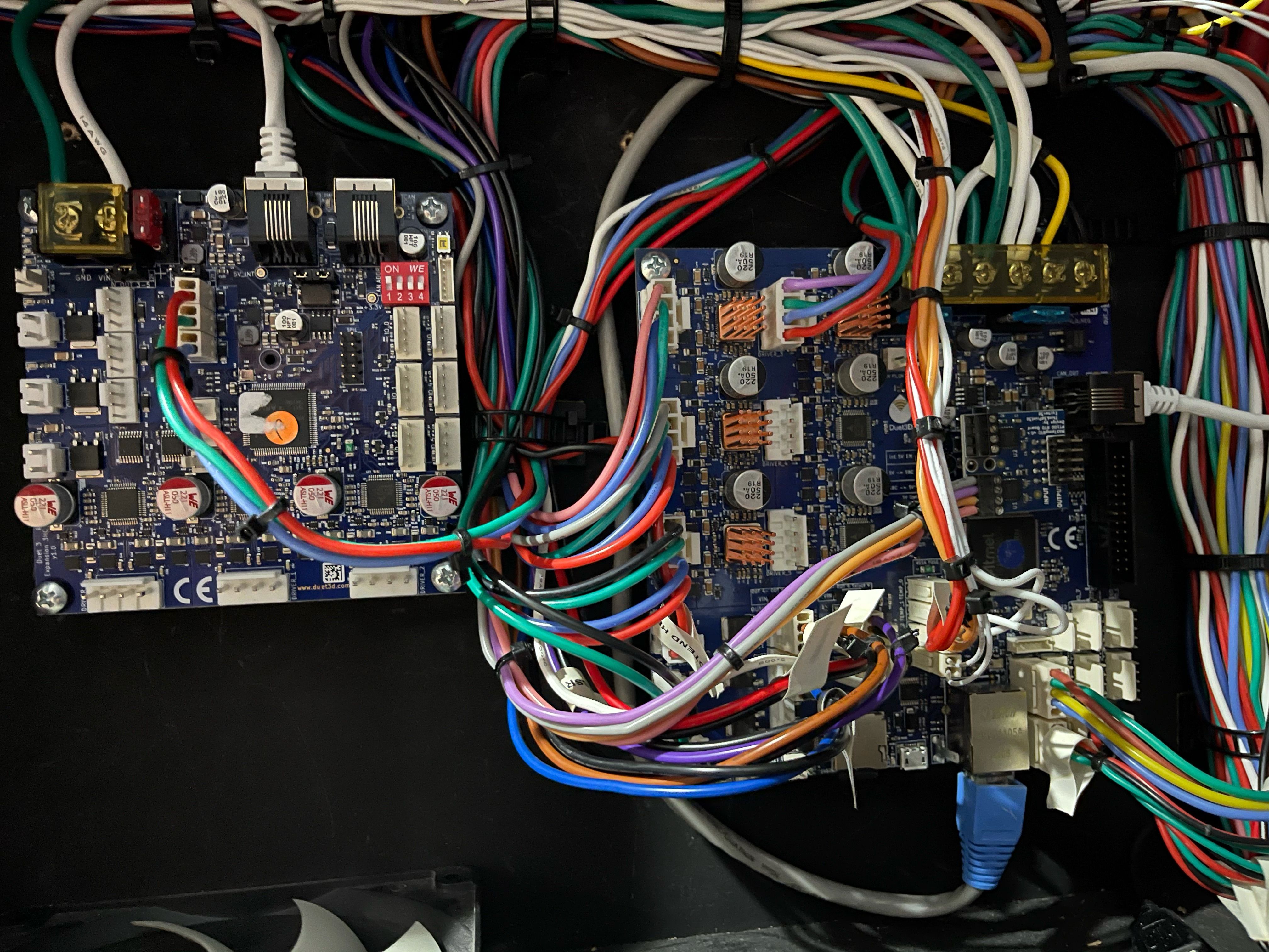
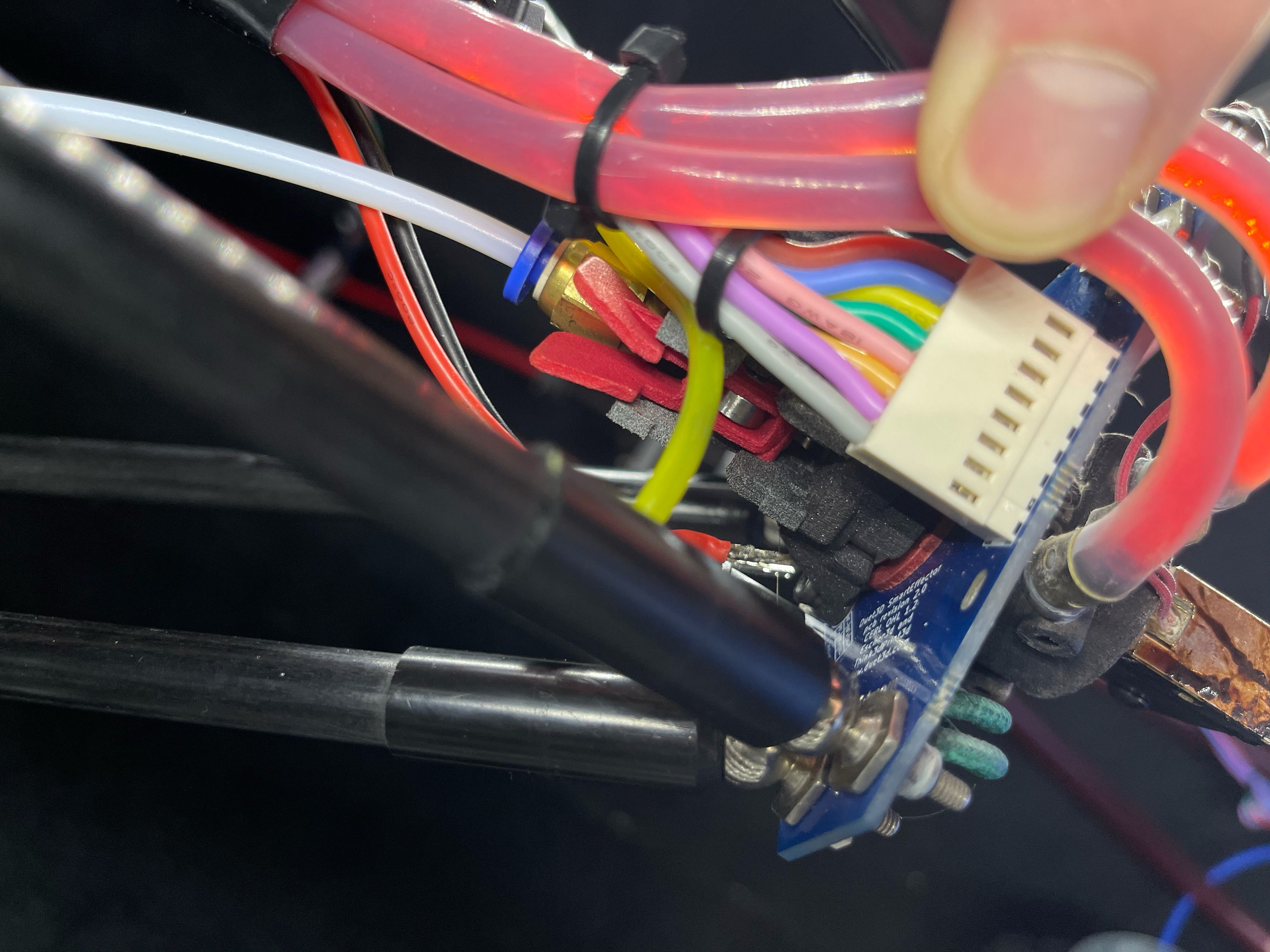
Photo of your wiring at the daughterboard?
-
from the duet 2 to duet 3 the rest of the hardware has been untouched. Its been a year but i think the pt100 was working at that time.
-
Can you get a closer show of the daughterboard itself? Can you remove it and reseat it?
-
@Phaedrux i removed it and checked the pins. seems to be seated properly. i have an extra smart effector i can try that i guess. if not i can buy another pt100. seems more like software.
-
Can you do this test on the daughterboard?
-
@Phaedrux pretty sure i can. give me a little bit
-
@Phaedrux so i found a 100ohm in my bin and wired it up. On channel P"spi.cs0". I am now getting 4.3c on the hotend. So i am going to put in the new smart effector when i can and order a new pt100 to be safe. thanks