Large Format Dowell to Duet conversion
-
The result from M308 indicates that the thermocouple for the bed is being read:
Sensor 0 type Thermocouple (MAX31856) using pin 1.spi.cs0, reading 9.3, last error: sensor open circuit, thermocouple type K, reject 50Hz
what is showing in DWC after you rerun config.g and are the heater error 0 errors no longer there.
@charles-fraser said in Large Format Dowell to Duet conversion:
Please can you recommend a thermistor that you know works well with your boards to replace these with? Thank you
Given that ou have a unknown (to us) extruder and bed it would be good to get something that works with the temperature ranges and mounting for those. Assuming the sensors you have linked are mechanically compatible then they should be good. The duet will be able to read them. For ease of wiring i suggest you get them on long enough leads that you dont have to use the (possibly questionable at this point) screw terminal distribution block you have in that system.
-
-
I've ordered the thermistors with very long leads.
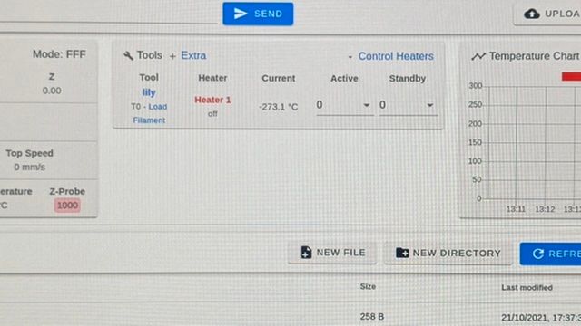
Please NB I dont get any temp reading with the termistor plugged right into the board either
The bed still does not show up in the interface and no temp from the thermo couple either
-
@charles-fraser ok I will have a few things to try once I am back at work.
-
@t3p3tony please lets get the basics working this week. I have the new thermistors and will be on it tomorrow x
-
@charles-fraser great so then the PT1000 sensors arrive start with the wired directly into the temp0 and temp 1 ports of the 3HC and update the M308 lines in your config.g to the following:
M308 S0 P"1.temp0" Y"PT1000"M308 S1 P"1.temp1" Y"PT1000"You will see i have specific the bed to go into temp0 and the hotend into temp1
-
Thanks Tony! I have ordered them the wrong size. The metal bit that is supposed to mount to the hear block is 5mm and not 3mm but I have connected them to the board to try and get something posting.
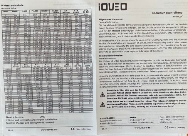
I have this thermistor in the heated bed and noz:

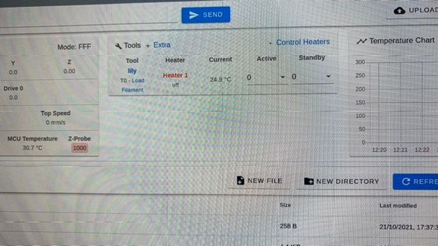
When I re create the settings you provided in the last message on the config.g file and update the system I get a good temp reading on the noz but nothing shows up for bed heater like it is not configured:
I’m ordering the correct sized thermistors now.
Lastly: Please can we also run some tests on motors, endstops, and any other parts we need to so that we can make sure we have components that work with these boards now so I can order the parts now? Is there a way to test the endstops and motors are working and set up right please?
-
So the temp for the noz thermistor was posting steadily:
And then I noticed all of a sudden the temperature readings were flying all over the place.
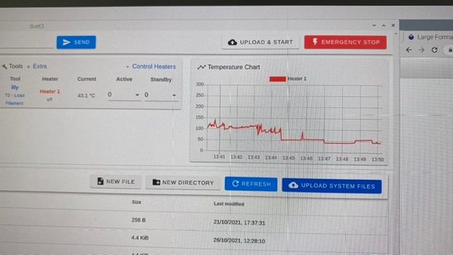
So I went down to the noz and when I held the thermistor I was getting a constant electric shock. Nothing too bad but enough to make me have to let go. I then laid the thermistor on the bed and the temps were 2000C
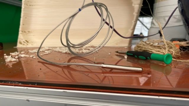
When I take the thermistor off the bed again this stops and it goes back to being stable.
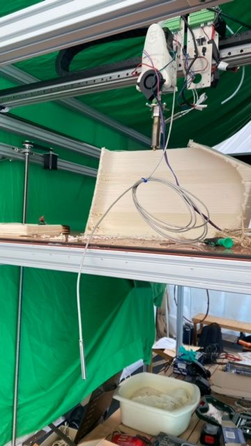
My thoughts are that the wind is cause the wire to wobble and that is what is causing the temp to wobble as the thermistor touches the frame/bed but should the thermistor be behaving like this ??? Surely all the electronics should be insulated inside that metal sheeth otherwise all the other electrical signals in the heating block such as the power going to the heat cartridge would short it out
I’ll test again with the thermistor tight on the board. What are the possible failures that could cause the thermistor to be electrocuting me in my hand? Does the nozzle / heating block need to be electrically isolated with only the thermistor and heat cartridge actually in contact with the block? I don’t understand how they can work together if the thermistor and heat cartridge are not electrically isolated from each-other / anything else. Please help!
I’ll try testing again with the thermistor plugged directly into the board
-
@t3p3tony okay so when I plug the thermistor into the board directly it no longer electrocutes me to touch it and if I lay it on the bed the temperature stays steady. I just can’t understand why though!
-
Okay so I removed all of the wires connected to the wiring block for the first extruder and I am using the wiring block and wires for the second extruder and this seems to have stopped it shorting at the nozzle end of the printer.
However when I set ‘active’ to 50 and click heater 1 to heat I get ‘fault’. Please advise
Many thanks
Charles -
@charles-fraser said in Large Format Dowell to Duet conversion:
Please can we also run some tests on motors, endstops, and any other parts we need to so that we can make sure we have components that work with these boards now so I can order the parts now? Is there a way to test the endstops and motors are working and set up right please?
Yes. Because there were a lot of issues to start with I have broken this down into a step by step process to keep on top of whats happening.
@charles-fraser said in Large Format Dowell to Duet conversion:
So I went down to the noz and when I held the thermistor I was getting a constant electric shock. Nothing too bad but enough to make me have to let go. I then laid the thermistor on the bed and the temps were 2000C
Ok so i would isolate the power to the heaters on the nozzle and anything else going through that set of connection blocks and investigate those - you should not be getting any form of electric shock ofc. What is particularly concerning is its unlikely you would feel a 24V DC shock so i suspect AC (unless it was a one off static shock). I can't really help much with AC wiring remotely. The wiring block is obviously a prime suspect if the heater itself is ok (based on your next post). Given all the issues that we have had with that wiring block I would be tempted to remove it from the system entirely if you can.
If you are now using the second extrude heater wires then did you update the heater connection on the Duet (its plugged into out1 on on the 3HC.
Also for the bed PT1000 can you confirm you have it plugged into temp0 and you made the config changes i mentioned?
M308 S0 P"1.temp0" Y"PT1000"Finally send config.g again to check for errors.
-
I'd strongly suggest you properly ground the printer frame for safety, and link the power supply negative to the frame, to avoid electrical noise pickup.
-
My god.... i need see a printed Benchy from this printer... a 1000 mm bechy, you can fit with a outboard motor
-
@peirof a benchy?
-
@rjenkinsgb thanks Robert J it is grounded as you describe already.
-
@t3p3tony thanks captain. I have disconected everything from the first extruder Mounting / block and am using the second block. This gets rid of all these low power tingly shocks when I touch the thermistor (not sudden but a painful prickle as long as I hold the thermistor when plugged into that block. I think the noz heater or fan wires must have rubbed down or melted down or something because that whole block is messed up. If you remember the BL-Touch was shorting too (I’m ordering a 3D Touch because it will come with some actual paperwork.
I’ll post the config G file here just now, I replaced all the lines you showed me however. I must have done something wrong. Thanks so much, sorry this is such hard work.
Is anyone at the Additt conference this week? We need to find a manufacture partner for this opensource pellet extruder that Juan has invented. His Spanish partners just dropped out www.recycl3dprint.com
-
Plugged into temp 0 and temp 1 on the 3HC
Configuration file for Duet 3 (firmware version 3.3) ; executed by the firmware on start-up ; ; generated by RepRapFirmware Configuration Tool v3.3.3 on Fri Oct 01 2021 16:59:54 GMT+0100 (British Summer Time) ; General preferences G90 ; send absolute coordinates... M83 ; ...but relative extruder moves ; Wait a moment for the CAN expansion boards to start G4 S2 ; Drives M569 P0.0 S1 ; physical drive 0.0 goes forwards M569 P0.1 S1 ; physical drive 0.1 goes forwards M569 P0.2 S1 ; physical drive 0.2 goes forwards M569 P0.3 S1 ; physical drive 0.3 goes forwards M569 P0.4 S1 ; physical drive 0.4 goes forwards M569 P0.5 S1 ; physical drive 0.5 goes forwards M569 P1.0 S1 ; physical drive 1.0 goes forwards M584 X0.0 Y0.1 Z0.2:0.4:0.5:0.3 E1.0 M350 X16 Y16 Z16 E16 I1 ; configure microstepping with interpolation M92 X80.00 Y80.00 Z400.00 E420.00 ; set steps per mm M566 X900.00 Y900.00 Z60.00 E120.00 ; set maximum instantaneous speed changes (mm/min) M203 X6000.00 Y6000.00 Z180.00 E1200.00 ; set maximum speeds (mm/min) M201 X500.00 Y500.00 Z20.00 E250.00 ; set accelerations (mm/s^2) M906 X2800 Y2800 Z1200 E1200 I30 ; set motor currents (mA) and motor idle factor in per cent M84 S30 ; Set idle timeout ; Axis Limits M208 X0 Y0 Z0 S1 ; set axis minima M208 X1200 Y2000 Z1600 S0 ; set axis maxima ; Endstops M574 X1 S1 P"io0.in" ; configure active-high endstop for low end on X via pin io0.in M574 Y1 S1 P"io1.in" ; configure active-high endstop for low end on Y via pin io1.in M574 Z1 S2 ; configure Z-probe endstop for low end on Z ; Z-Probe M558 P9 C"^1.io1.in" H100 F120 T6000 ; set Z probe type to switch and the dive height + speeds G31 P500 X0 Y0 Z2.5 ; set Z probe trigger value, offset and trigger height M556 S50 X0 Y0 Z0 ; set orthogonal axis compensation parameters M557 X15:215 Y15:195 S20 ; define mesh grid ; Heaters M308 S0 P"1.temp0" Y"PT1000" M307 H0 B1 S1.00 ; enable bang-bang mode for the bed heater and set PWM limit M140 H0 ; map heated bed to heater 0 M143 H0 S80 ; set temperature limit for heater 0 to 80C M308 S1 P"1.temp1" Y"PT1000" ; configure sensor 1 as thermistor on pin temp0 M950 H1 C"1.out1" T1 ; create nozzle heater output on out1 and map it to sensor 1 M307 H1 B0 S1.00 ; disable bang-bang mode for heater and set PWM limit M143 H1 S300 ; set temperature limit for heater 1 to 300C ; Fans M950 F0 C"out8" Q0 ; create fan 0 on pin out8 and set its frequency M106 P0 S0 H T45 ; set fan 0 value. Thermostatic control is turned on M950 F1 C"out9" Q500 ; create fan 1 on pin out9 and set its frequency M106 P1 S1 H-1 ; set fan 1 value. Thermostatic control is turned off ; Tools M563 P0 S"lily" D0 H1 F0:1 ; define tool 0 G10 P0 X100 Y100 Z0 ; set tool 0 axis offsets G10 P0 R0 S0 ; set initial tool 0 active and standby temperatures to 0C ; Custom settings are not defined -
@charles-fraser ok so do you get errors when config.g is run using M98? and are both heaters showing correctly in the U and heating when commanded?
-
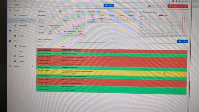
27/10/2021, 13:47:35 M98 P"0:/sys/config.g"
=
27/10/2021, 13:47:36 Error: M143: Heater 0 does not exist
27/10/2021, 13:47:36 Error: M307: Heater 0 not found -
