Comparing klipper and RRF input shaper data collection
-
@gixxerfast That's odd, what I posted works fine for me (using an SBC I've not tested it on a standalone system). Have you tried it? Did you get errors?
-
@gloomyandy Yes, I got errors and I run standalone.
For example:
2021-11-18 20:33:03	M98 P"0:/macros/test/resonancetest.g"
max_accel 10000.000 min freq 5.0 max freq 133.3333
Testing 5
Error: in file macro line 31 column 8: meta command: expected string expression
When I fixed as described it seems to work fine and produced the gcode-file
-
@gixxerfast Looks like there is a difference between SBC and standalone macros then @chrishamm
-
@gloomyandy
So. I assume this is the current standalone version of Andys script (with spaces instead of tabs") ) Thanks again!
) Thanks again!var title = "Klipper style vibration test V0.3" var axis="Y" var datarate=1320 var stime = state.upTime var min_freq = 5.0 var max_freq = 10000/75 var accel_per_hz = 75 var hz_per_sec = 1 var freq = var.min_freq var max_accel = var.max_freq * var.accel_per_hz var X = 150.0 var Y = 150.0 var sign = 1.0 var t_seg = 0 var accel = 0 var max_v = 0 var L = 0 var nX = 0 var old_freq = 0 var filename = "/gcodes/vtest_" ^ var.axis ^ ".gcode" echo "max_accel " ^ var.max_accel ^ " min freq " ^ var.min_freq ^ " max freq " ^ var.max_freq echo >{var.filename} " " echo >>{var.filename} "M201 X" ^ var.max_accel ^ " Y" ^ var.max_accel echo >>{var.filename} "M205 X0 Y0" echo >>{var.filename} "G91" echo >>{var.filename} "M400" echo >>{var.filename} "G4 S1" echo >>{var.filename} "M956 P0 A0 S" ^ (var.max_freq - var.min_freq) * var.datarate * var.hz_per_sec echo "Testing " ^ floor(var.freq) echo >>{var.filename} "echo " ^ var.freq while var.freq < var.max_freq + 0.000001 set var.t_seg = 0.25 / var.freq set var.accel = var.accel_per_hz * var.freq set var.max_v = var.accel * var.t_seg echo >>{var.filename} "M204 P" ^ var.accel ^ " T" ^ var.accel set var.L = 0.5 * var.accel * (var.t_seg*var.t_seg) set var.nX = (var.sign * var.L) echo >>{var.filename} "G1 " ^ var.axis ^ var.nX ^ " F" ^ var.max_v*60 echo >>{var.filename} "G1 " ^ var.axis ^ -var.nX set var.sign = -var.sign set var.old_freq = var.freq set var.freq = var.freq + (2. * var.t_seg * var.hz_per_sec) if floor(var.freq) > floor(var.old_freq) ;echo >> var.filename "echo " ^ floor(var.freq) echo "Testing " ^ floor(var.freq) echo >>{var.filename} "G90" echo "total time " ^ state.upTime - var.stimeVoron V2.4 (#1317) with Duet 3 Mini5+ Wifi and 1LC v1.1 Toolboard
Voron V0.1 (#637) with Duet 3 Mini 5+ Wifi and 1LC v1.2 Toolboard
Ender 3 Pro with BTT SKR-2 + RRF -
@gloomyandy said in Comparing klipper and RRF input shaper data collection:
@pixelpieper Thanks for pointing this out.
Honestly I'm not sure if ramping the frequency helps capture a better data set or not, that is simply the way in which klipper does it and was what I was aiming to investigate. I was just pointing out that at the moment if you use standard RRF and my script you will not be capturing all of that data. From your second post I would have thought that this may be a bad thing if the klipper sweep is operating correctly?
Yes.
As to the actual sampling rate used again this is a difference between RRF and klipper (klipper typically samples at 3200 samples/s). I have no idea if this is significant or not (it certainly means that klipper will have more samples to process). The shaper tuning only seems to consider relatively low frequencies (a max of 200Hz for RRF and I think something similar for klipper), so in theory so long as the sample rate is above 400 samples/second then it should be usable.
Yes, as long as we stay above 400 Hz we are fine.
I suspect that one of the key advantages that the klipper method has is that it just provides more usable samples than that produced by the current RRF method. Perhaps it might be better to collect several datasets using the RRF method and combine them to increase the number of usable samples?
That should work and will allow us to do a longer FFT which in turn results in a finer frequency resolution.
I'd also note that the current plugin (and the how to use instructions) do not make any mention of what acceleration to use, perhaps it would be better to set a higher acceleration if using this method? I wonder if it would be possibly to apply a higher acceleration value just for the deceleration phase of the move as I assume it is this that provides the impulse in this case?
Accelleration and decelleration equally produce the same kind of oscillations, it should not matter.
One final thought, I've seen a number of plots that have been produced by myself and other posters in which there seems to be a significant low frequency peak when using the current RRF method, this does not seem to be present with the klipper method. See the first two graphs above, one has a peak around 16Hz that does not seem to be present in the klipper data. I'm not sure which one is correct, but from measuring the ringing on actual prints this peak does not seem match.
Someone earlier in this thread mentioned that Klipper filters very low and high frequency components, hence it is expected that these peaks would dissappear.
Voron V2.434 / Duet 3 Mini5+, Duet 3 Expansion Mini 2+, Duet 1LC V1.1 Toolboard
Voron V0.250 / Duet 2 Maestro -
@o_lampe said in Comparing klipper and RRF input shaper data collection:
@pixelpieper said in Comparing klipper and RRF input shaper data collection:
based on theory each acceleration and deceleration contain all the frequency components
Wouldn't it take a certain time for the frame to get into resonance? If so, the frequency in question would need to be applied for longer than just the short accel/deccel time?
No, this is just the stimmulating signal - the closest equivalent I could think about would be a tuning fork, it just needs a very short tap to resonate for a long time.
-
@pixelpieper said in Comparing klipper and RRF input shaper data collection:
Someone earlier in this thread mentioned that Klipper filters very low and high frequency components, hence it is expected that these peaks would dissappear.
Any filtering in klipper does not really apply in this case. See the first two graphs in my first post, neither of those is using anything to do with klipper and the first image has a very clear peak at 16Hz that is not present in the second image. Both graphs are produced by the RRF accelerometer plugin.
-
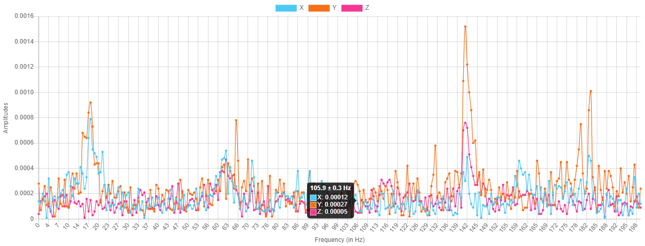
After resolving the issue with the acceleration settings, I've been trying to understand the source of the peaks I was seeing around 100Hz (which only seem to show up in X). I had a close look at my print head and discovered a loose mounting bolt! After tightening this I've re-run all of the tests:
RRF input shaper plugin X data:
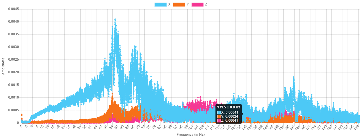
Klipper style X data:
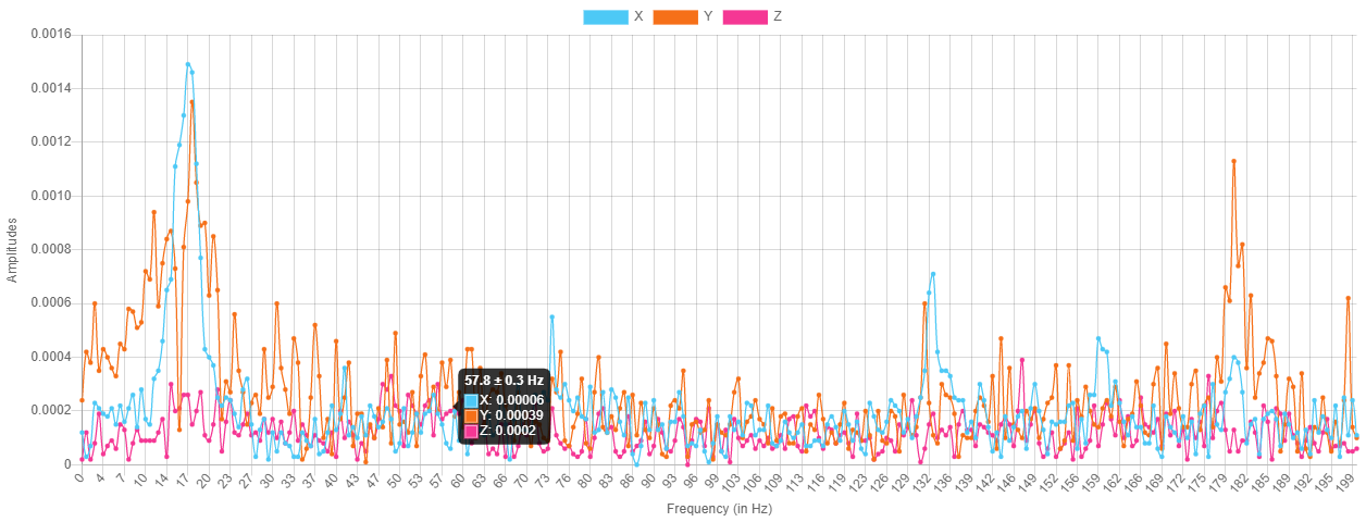
RRF input shaper plugin Y data:
klipper style Y data:
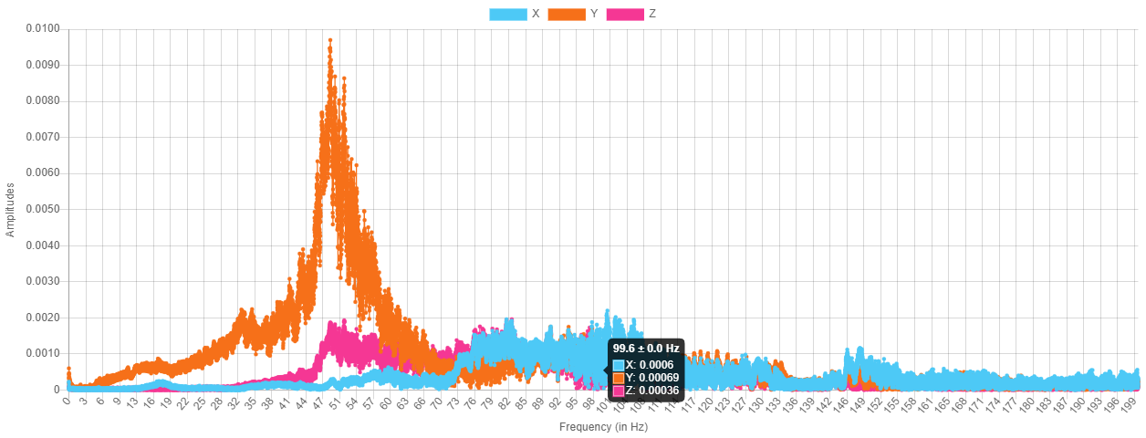
The klipper input shaper script allows you to combine multiple input files, so I used that to produce a recommendation:
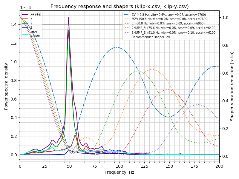
I'm reasonably happy that this output matches the ringing I've been seeing on actual test prints. On these the ringing was worse on Y and measuring them gave a frequency of approx 46Hz.
For me I would say that the klipper style frequency sweep produces better data to analyse than the single move used by the current RRF input shaper plugin.
-
@gloomyandy, i agree with you. I think in the klipper style data you can also see the resonance detected with RRF recording.
My conclusion is to find all or at least most resonances of a printer more test moves are necessary.
Do you agree?
-
@gixxerfast BTW will this work with the standard 3.4 b6 build of RRF?
-
@pcr said in Comparing klipper and RRF input shaper data collection:
@gixxerfast BTW will this work with the standard 3.4 b6 build of RRF?
Oh, this is @gloomyandy s work. I use that RRF-version but I have only executed his script and have yet to figure out how to "Klipperize" the files to be able to run the calibrate_shaper script.
As said above, there's still a limitation in RRF regarding the 64K of samples that AFAIK hasn't been fixed yet.
-
@pcr Short answer no.
Longer answer:
At the moment beta6 does not allow you to capture more then 64K samples. But you may be able to get it to work by using a lower capture data rate in M956 and then modifying the script to match, but this is not something I have tried. It looks like the next RRF build should have support for larger captures: https://github.com/Duet3D/RepRapFirmware/commit/020e9fbc171b1a519d9b8f01df2e68f1c273beaf -
 undefined gloomyandy referenced this topic
-
undefined gloomyandy referenced this topic
-
undefined gloomyandy referenced this topic
