Issues with pressure advance since RRF 3.4
-
@argo I have been meaning to do a test between the two firmware versions for a few weeks now and finally got a chance to do so on the weekend.
I have two identical cartesian bedslinger machines both running everything directly off a MB6HC with SBC. One is running on version 3.3 and the other is running on version 3.4.0. I am not presently using input shaping. Both machines have direct drive Titan Aqua extruders.
I printed a 50mm single outline square with a 1mm gap in one side, so that I can measure line starts and ends as well as seeing what happens at the corners of the print. I used a PA setting of 0.055 using ABS at a print speed of 45mm/s for both machines and a retraction of 0.4mm.
I did not see a difference between the two firmware versions, either at the corners or at line starts or ends. This was determined by measuring the difference in thickness at line starts and ends as well as the first corner vs the thickness midspan between the line start and the first corner. In each case I measured the same difference.
Based on some of your earlier comments and those from @dc42 it seems therefore that this problem may be confined to systems running with an attached tool board. Did you see any difference in printing when both machines were running on version 3.3 firmware? If not, then you can pretty much eliminate the mechanical hardware difference between the two machines as a cause of the problem.
-
Thanks for testing as well.
My bed slinger is not affected by this issue. RRF 3.3 and 3.4 look identical, though I find with RRF 3.4 and enabled input shapers, PA can’t be tuned to get as sharp corners as with 3.3.As with the CoreXY machine (+Duet 1LC and Bondtech LGX extruder) RRF 3.3 does look better than RRF 3.4 (both disabled IS). But even the RRF 3.3 results with this machine do not look as good as with the bed slinger.
I can’t remember I was having PA issues with this machine in the past. Only thing that changed was the Duet 1LC. And I don’t know what hardware issue may cause this as its only affecting corners and not infill lines. -
To rule out the extruder I changed from a Bondtech LGX extruder to a LDO Orbiter 2.0.
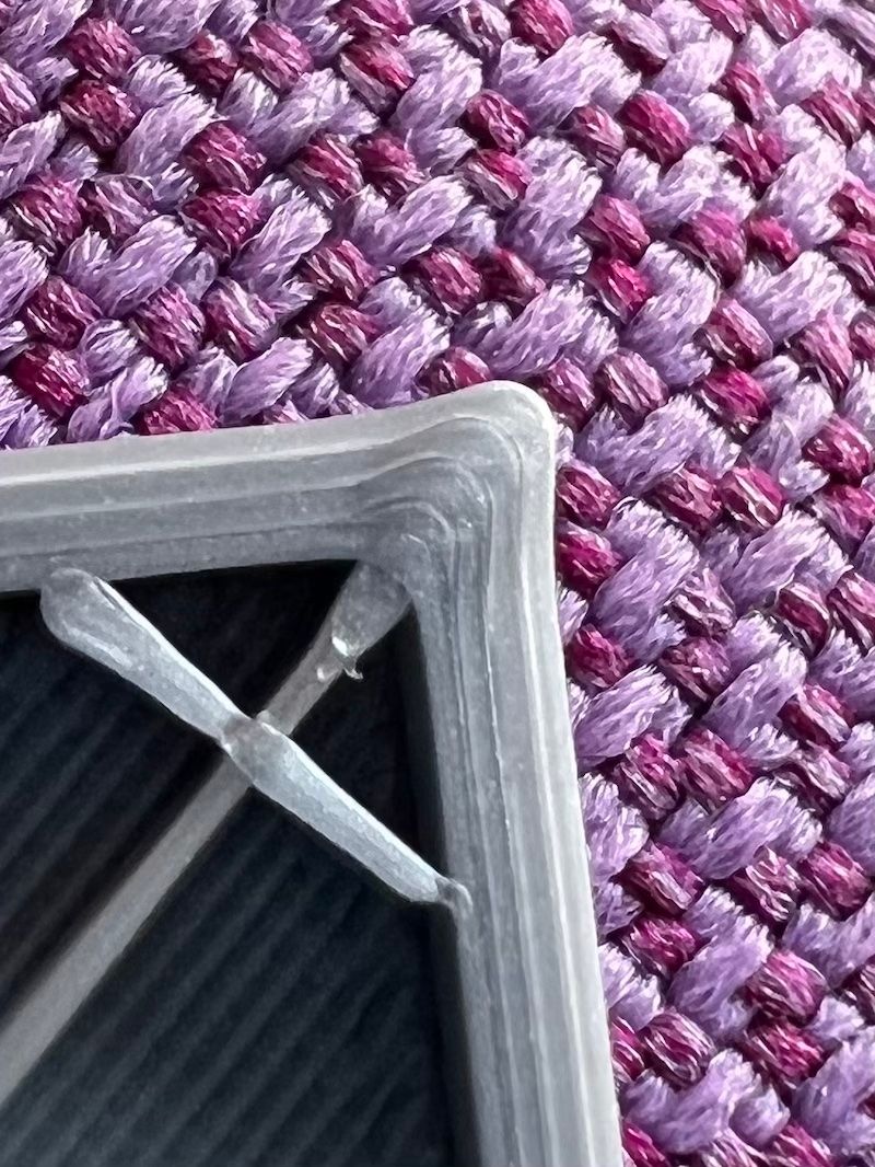
The Orbiter has almost no backlash and also has a shorter tube between gears and hotend compared to the LGX.Printing PLA, PA was set to 0.055 which usually is a good value for PLA and a direct drive extruder. The result is more or less the same. Infill lines do look fine and string but corners are bulging:
-
@argo Based on everything you've written, the most logical conclusion still seems to be that there may be a problem with RRF 3.4 running with the toolboard. Nevertheless there is one thing that caught my attention and which I think is worth looking into before trying to go further down the rabbit hole as this may be exacerbating (if not causing) the problem.
Looking at your print settings further back in this thread I see that you are running accelerations of 2000mm/s^2 for perimeters and 5000mm/s^2 for infill together with speeds of 160mm/s for perimeters and 250mm/s for infill.
If the equation shown on the old PA dozuki page is still used for pressure advance then the actual amount of advance is dependent on both the PA factor as well as the acceleration setting used. This means that for the same PA factor your two different accelerations (for perimeters vs infill) will give correspondingly different amounts of actual advance. Calculating the actual amount of advance resulting from your settings under the two different scenarios shows that you will have an increase in PA amount that is almost in direct (linear) proportion to the higher speed you are using for your infill vs the perimeter. However, as the plastic is non-newtonian in nature the relationship between print speed and required amount of advance will not be linear and that may be the reason why you cannot find a PA setting that works for both the corner as well as the infill.
Looking at your last print above it seems that you still have too much advance for your infill (line starts are very thick whereas line ends are excessively thin right at the end) but yet not enough for the perimeters (bulging at the corners).
I would suggest to try tuning your PA factor to the correct amount required for your perimeters (to get a sharp corner) and then tuning the actual amount of advance for the infill by tuning (down) the acceleration used for the infill until you find the right balance that works for both perimeters as well as infill. In that way you may be able to actually eliminate this problem (Even though it does not explain the difference between the results achieved with RRF3.4 vs RRF 3.3).
Of course the above scenario does once again point to the fact that PA really needs to be speed sensitive and indeed some others users in this thread have also pointed this out.
I hope the above helps.
-
Very interesting idea.
To test it I printed this with everything set to 100 mm/s speed and 1500 mm/s acceleration.
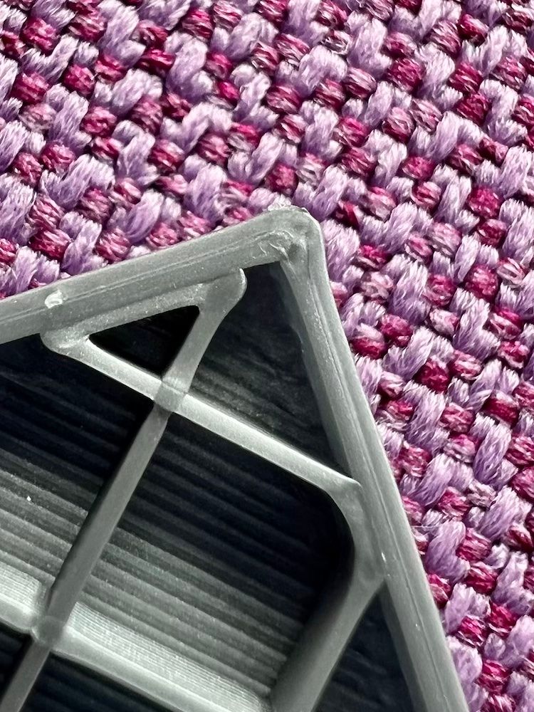
PA was set to 0.056 (PLA).Here is the result. In my opinion PA should be even lower (maybe 0.052) to increase the infill quality but the perimeters are still bulging.
-
@argo That does seem to have made quite a difference at least to the infill so far. The only other thing I can think of as far as settings are concerned relates to retraction. This does play quite a big role in determining the quality of the line start which can otherwise make quite a big blob.
Depending on the slicer and the slice settings used you may find that a retract movement may or may not be accompanied by a corresponding unretract at the beginning of the next line (you will have to look at your gcode file to see). If the slicer does do a full unretract then you may find that this will cause a blob at the start of any line and you will not be able to control this with PA as that will only make the blob bigger while narrowing down the end of the line. What I have therefore found is that it is necessary to do a certain amount of retract at the end of a line without unretracting at the start of the next line. If you tune the amount of retract correctly (and ensure that it does not unretract) then you should more or less be able to prevent a blob from forming at the line start while using the PA to tune the line end and corners (as far as possible). I can't at this point explain why the above seems to be necessary, just that it does seem to be the case.
If I look at the last print you have shown above then it does look to me as if you have blobs forming at line starts on infill. It also looks like you have a line starting and ending at the corner junction of the inside perimeter but I cannot say for sure so maybe just check your slicer to see whether that is so.
If you can get rid of the blobs/excess line thickness at the start of a line in the above manner then it would give you a bit more freedom to further adjust your PA factor to optimize the line ends which may or may not improve the corners.
The above is all I can suggest at this point as far as settings go. If that does not sufficiently correct the problem then you are back to having to look at firmware or hardware.
-
@argo Do you have a picture of that cube showing a corner that is not at the start/end of the inner perimeter? Would be interesting to see what that looks like.
-
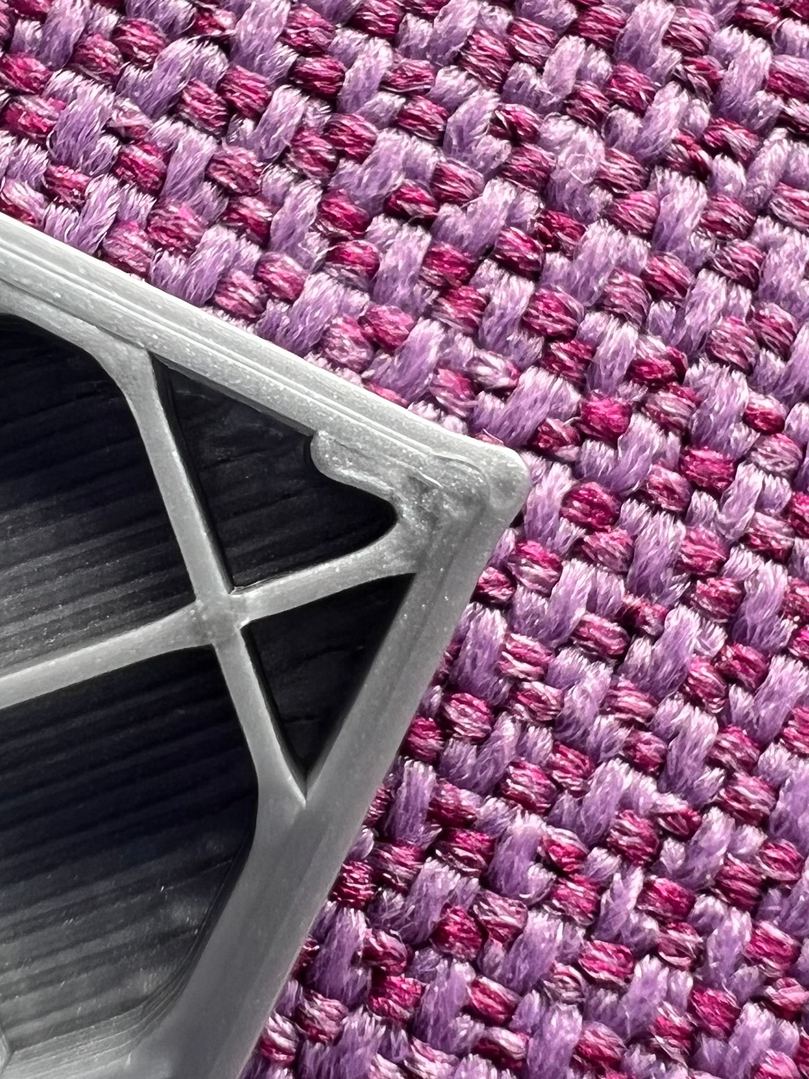
On the following picture you see a corner without retraction. This was also a very slow test at 40 mm/s to rule out overshooting corners caused by too high speed.
-
@argo I am not sure whether it is so clear from my previous explanation but what I mean is not to print without retraction but to use retraction together with a negative extra restart distance specified in your slicer. I know Simplify3D and PrusaSlicer do have these settings available but I am not sure about other slicers. Using this setting will result in a shorter unretract distance being used after any retraction has been done. This would help to narrow down the start side of any print line and therefore give you some additional scope for adjusting your PA settings for line ends or corners.
-
3 corners out of 4 never have any retraction with the test objects I print. Seam is set to aligned so the seam gets placed always at the same corner. To show that the retraction isn’t the culprit I showed one of the other corners which looks the same. This would with my understanding rule out retraction issues. Or did you mean something else and I misunderstood you?
-
@argo
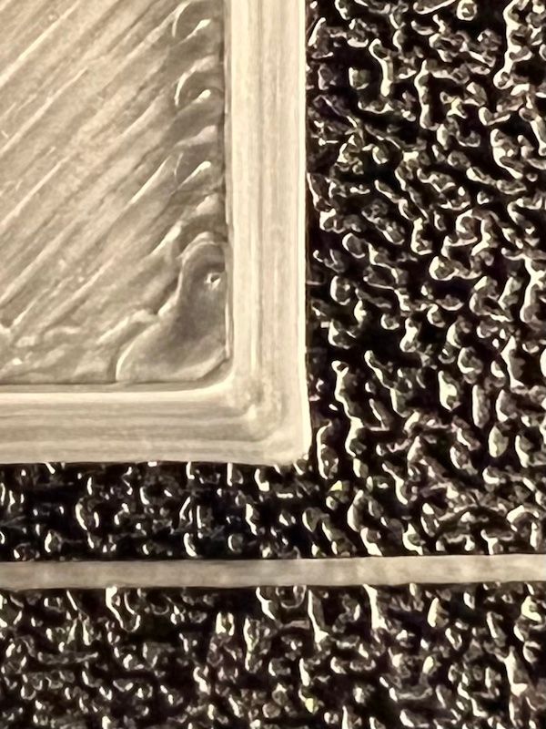
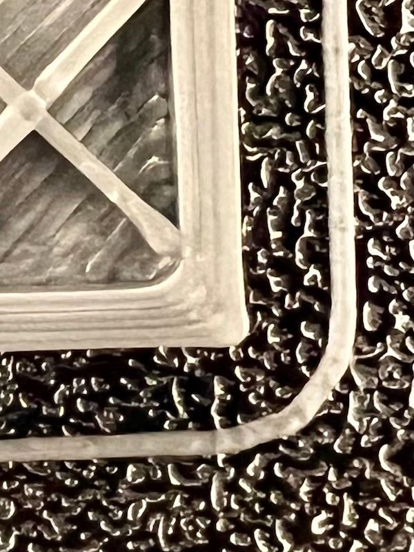
My guess, after looking at the photos all once, is that the problem might be the value of the overlap between fill lines and outside perimeters set in the slicer.On all photos where the corner was pushed out, a fill line ends directly on that corner.
Here, Here and Here
Pay attention to this area in the last photo...
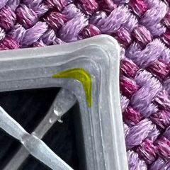
One (two ?) photo where it isn't is a Z-seam that has pushed the outside perimeter outwards.
HERE and probably also HERE !?So I would suggest... print the same rectangle WITHOUT the Infill to see if it could be due to the overlap of the infill and the outer wall.
Or change the percentage of infill so that the infill doesn't end up in the corners.If you compare the two pressure parts in the first photo, I would say that the flow is too high in the lower pressure part.
(The reason could be a different temperature or a different filament diameter or similar.)Therefore, determine the flow for the respective filament again and then determine the PA value again.
You suspect that the update of the RRF can be the reason for this problem.
Can you say with certainty that you used the exact same filament (same spool) and that ALL the settings were identical?
A filament can have a different diameter per spool.Because other people and even your other printer do not show these problems, I would assume that something has changed between these two printouts, except for an update of the firmware.
It's just my guesses.

Text was translated using Google Translate, so some sentences may be harder to understand.
-
He can repeat the test printing external perimeters first, to rule that out.
-
@ccs86 said in Issues with pressure advance since RRF 3.4:
He can repeat the test printing external perimeters first, to rule that out.
That would also be a possibility.
I would omit the infill completely for the test, then the result would be "unadulterated".
In my opinion, printing the outer walls before the infill would then be a refinement process to optimize the print. -
@norder said in Issues with pressure advance since RRF 3.4:
@ccs86 said in Issues with pressure advance since RRF 3.4:
He can repeat the test printing external perimeters first, to rule that out.
That would also be a possibility.
I would omit the infill completely for the test, then the result would be "unadulterated".
In my opinion, printing the outer walls before the infill would then be a refinement process to optimize the print.Why omit the infill? I thought one purpose of this testing was to confirm or deny that PA was working differently in his infill and perimeters?
If you print external perimeters first, they will not be influenced by the infill, or by perimeter overlap. This should show more directly how PA is handling these outside corners.
-
@argo said in Issues with pressure advance since RRF 3.4:
3 corners out of 4 never have any retraction with the test objects I print. Seam is set to aligned so the seam gets placed always at the same corner. To show that the retraction isn’t the culprit I showed one of the other corners which looks the same. This would with my understanding rule out retraction issues. Or did you mean something else and I misunderstood you?
I think you may have misunderstood me, but not to worry
 The only reason I am bringing up retraction (and more specifically negative extra restart distance when doing retractions) is because of the role that will play in trying to assess optimal PA factors and the PA factor in turn then would play a major role in limiting bulging at corners. The retraction settings mentioned before therefore end up playing only an indirect role in determining what can happen at corners. What I am aiming at is to try to get to the highest possible PA factor that will allow proper printing of infill but also produce the greatest reduction of bulging at corners.
At this stage it is a bit difficult to say from the last image posted whether there is still any scope for increasing PA. This is because when looking at the infill I can see that line starts are still wider than line ends. If the line start widths are reduced by adding a negative extra restart distance to retractions it will be easier to see from the line ends whether you can actually increase the PA factor any further.
-
@norder said in Issues with pressure advance since RRF 3.4:
@argo
My guess, after looking at the photos all once, is that the problem might be the value of the overlap between fill lines and outside perimeters set in the slicer.Good observation. It does look as if there may be an excessive infill overlap on the corner which may be pushing it out a bit. If you get your line starts and ends printing correctly then you should also be able to reduce the infill overlap you are using without running into problems with infill not connecting to the perimeter.
-
@ccs86 said in Issues with pressure advance since RRF 3.4:
Why omit the infill? I thought one purpose of this testing was to confirm or deny that PA was working differently in his infill and perimeters?
If you print external perimeters first, they will not be influenced by the infill, or by perimeter overlap. This should show more directly how PA is handling these outside corners.I wanted to get to the bottom of the problem of the bulging corners, but the PA doesn't interest me at first.
Even if the outer walls are printed first, it can still happen that when the infill is printed, the wall can be deformed as it might still be soft, especially when printing very quickly.
And in order to eliminate all these possible falsifications from the outset, one should print without infill.
Which really shouldn't be a problem.If the corners then look the way you want them to, you know where the error is and you can try to optimize them with some settings in the slicer, for example by printing the walls before the infill or by setting the infill so that the corners are not deformed can etc. pp
Text was translated using Google Translate, so some sentences may be harder to understand.
-
I’ll just do both tests.
One without infill and one with the setting „perimeter first“.
But I’m away from my printer right now until tomorrow. So please be patient >) -
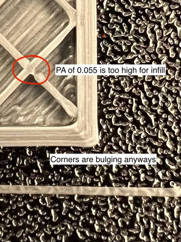
Printed all three test object at once. PA was set to 0.055 which is a bit too high imo (see infill lines) but infill / perimeter quality is always a compromise and I try to favour perimeters in this case. Input Shapers are off btw. Enabling those and things get even uglier.
-
@argo why do you point at the infill intersection break as evidence for PA tuning? There is no PA action at that point, since those are uninterrupted straight lines, which cross.
More important would be at changes in direction, but it would be much more helpful if you labeled the direction of travel for each infill line you are considering, since without it you can't guess.
