1XD Closed Loop Servo Setup
-
Your link doesn't work, and can't find it on the main leadshine site so here is the manualslib link
https://www.manualslib.com/products/Leadshine-Eld2-Rs400-11165537.html
Following this as I have to setup two EL5-400's soon with ACM604 motors.
-
@shauncro Thanks for adding a valid link to the manual. After reading through more of the manual I'm seeing how much more complex driving a servo is than a stepper.
If anyone can recommend a servo driver that you are having success driving with the 1XD please let me know as I am open to switching if it would simplify things.
-
@code7 I'll let you know how my setup goes, had them sitting in a box for a while, and finally have the time to get started. I'm running the 6HC though, so will be a bit different. Have you tried to use the leadshine tuning software?
-
@code7 We sucesfull use Oriental Motor AZD-K series absolute enconder pulse-input type motor driver with a 1XD board.
https://www.orientalmotor.eu/Products/Stepper_motors/Closed_loop_stepper_motor_packages/az_dc/?&filter1=Standard&filter2=60+mm&feld040=0&arid=22968&dwn=artnrConfig example:
;######################### AXIS BOARD DRIVERS DECLARATIONS ######################### M569 P40.0 S1 ; physical drive 40 goes forwards X M569 P41.0 S0 ; physical drive 41 goes backwards Y1 M569 P42.0 S0 ; physical drive 42 goes backwards Y2 M569 P43.0 S0 ; physical drive 43 goes backwards Z1 (Z) M569 P44.0 S0 ; physical drive 44 goes backwards Z2 (U) M569 P45.0 S0 ; physical drive 45 goes backwards Z3 (V) ; ############################## DRIVER PARAMETERS SETTINGS ############################## M584 X40.0 Y41.0:42.0 Z43.0 U44.0 V45.0 ; axis drive mapping M350 X1 Y1 V1 Z1 U1 V1 I1 ; configure axis microstepping with interpolation M92 X150.53 Y150.53 Z100.12 U100.12 V100.12 ; axis steps per mm M566 X900.00 Y900.00 Z500.00 U500.0 V500.0 ; set maximum instantaneous speed changes (mm/min) M203 X18000.00 Y18000.00 Z12000.00 U12000.00 V12000.00 ; set maximum speeds (mm/min) M201 X300.00 Y300.00 Z500.00 U500.00 V500.00 ; set accelerations (mm/s^2) ;################################# AXIS ENDSTOPS ################################# M574 X1 S1 P"!40.io0.in" ; configure active-high endstop for low end on X via pin 40.io0.in M574 Y1 S1 P"!41.io0.in" ; configure active-high endstop for low end on Y via pin 41.io0.in M574 Z2 S1 P"!43.io0.in" M574 U2 S1 P"!44.io0.in" ; configure active-high endstop for high end on U via pin 44.io0.in M574 V2 S1 P"!45.io0.in" ; configure active-high endstop for high end on V via pin 45.io0.in 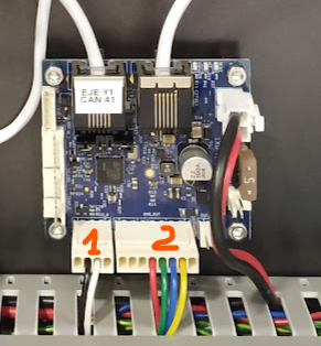
1 - Step area defined in the axis as virtual "endstop"
2 - Step and dir signals to motor driver -
@shauncro Thanks for keeping me in the loop. I haven't tried the tuning software yet. Maybe once I get the closed loop servo turning.
-
@marcossf Thanks for the detailed recommendation. I'll check it out.
-
@code7 please share your config.g file.
Which axis do you want to drive with this servo motor?
-
@dc42 The closed loop servo is on drive 122.0 on the 1XD Exp Board. I'm able to turn the motor briefly until I receive the "Motor speed out of control" Alarm from the ELD2 servo driver.
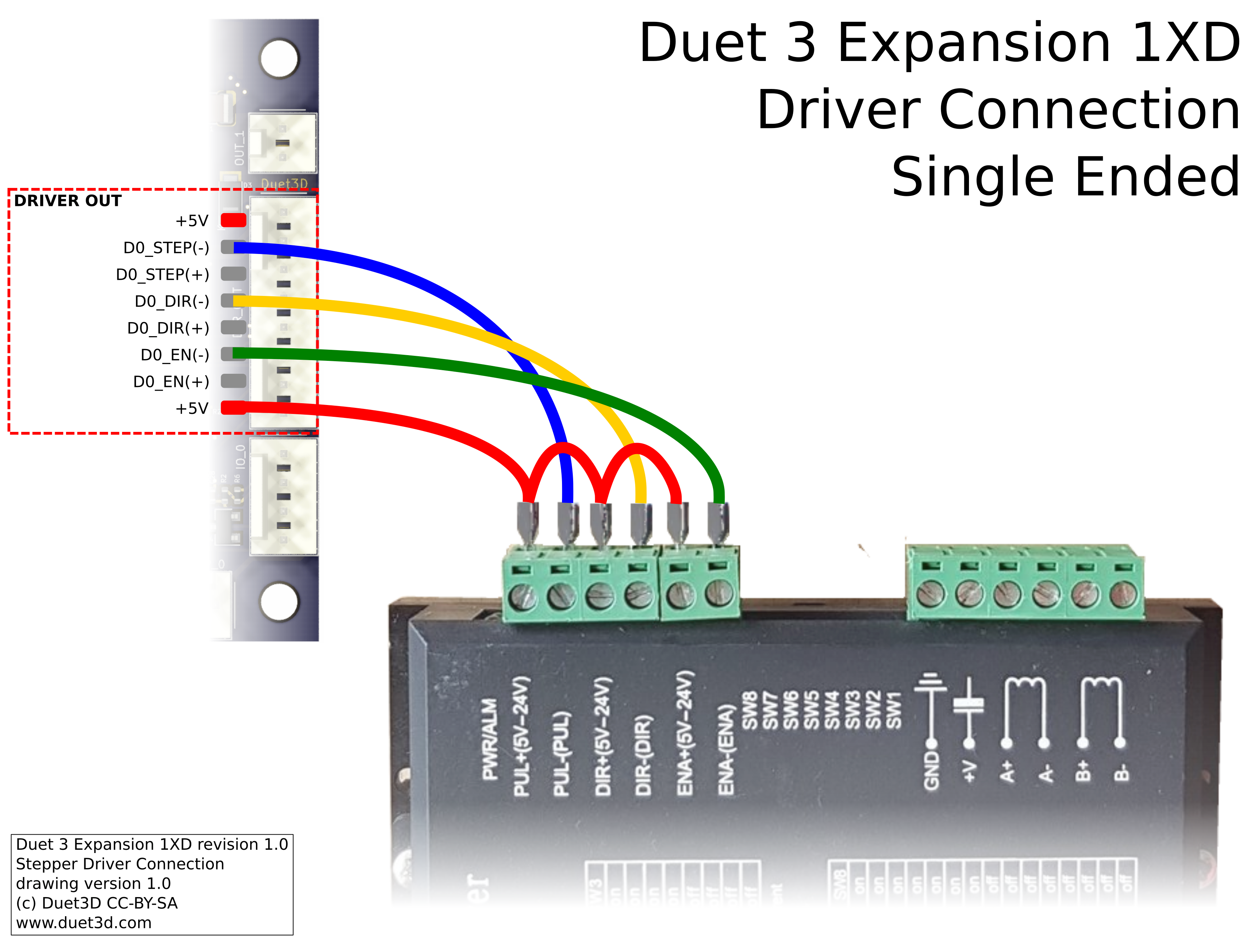
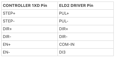
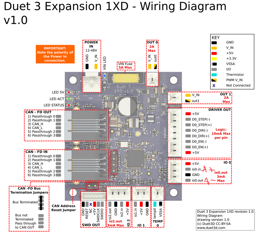
This is how I have it wired:
ELD2 Manual:
http://leadshineusa.com/UploadFile/Down/ELD2-RS70-- User Manual_2021_Ver1.09.pdfConfig:
G4 S2 ; wait a moment for the CAN expansion boards to start ; Drives M569 P0.0 S0 ; physical drive 0.0 goes backwards M569 P0.1 S0 ; physical drive 0.1 goes backwards M569 P0.2 S1 ; physical drive 0.2 goes forwards M569 P122.0 S0 ; physical drive 121.0 goes backwards M584 X0.0 Y0.1 Z0.2 E122.0 ; set drive mapping M350 X16 Y16 Z16 E1 I1 ; configure microstepping with interpolation M92 X80.00 Y80.00 Z400.00 E100.00 ; set steps per mm M566 X1200.00 Y1200.00 Z24.00 E300.00 ; set maximum instantaneous speed changes (mm/min) M203 X9000.00 Y9000.00 Z360.00 E6000.00 ; set maximum speeds (mm/min) M201 X500.00 Y500.00 Z100.00 E5000.00 ; set accelerations (mm/s^2) M906 X800 Y800 Z800 E1200 I50 ; set motor currents (mA) and motor idle factor in per cent M84 S30 ; Set idle timeout ; Axis Limits M208 X0 Y0 Z0 S1 ; set axis minima M208 X235 Y235 Z260 S0 ; set axis maxima ; Endstops M574 X1 S1 P"io1.in" ; configure switch-type (e.g. microswitch) endstop for low end on X via pin io1.in M574 Y2 S1 P"io2.in" ; configure switch-type (e.g. microswitch) endstop for high end on Y via pin io2.in M574 Z1 S1 P"io3.in" ; configure switch-type (e.g. microswitch) endstop for low end on Z via pin io3.in ; Z-Probe M558 P0 H5 F120 T6000 ; disable Z probe but set dive height, probe speed and travel speed M557 X15:215 Y15:195 S20 ; define mesh grid ; Heaters M308 S0 P"temp0" Y"thermistor" T100000 B4092 ; configure sensor 0 as thermistor on pin temp0 M950 H0 C"out0" T0 ; create bed heater output on out0 and map it to sensor 0 M307 H0 B1 S1.00 ; enable bang-bang mode for the bed heater and set PWM limit M140 H0 ; map heated bed to heater 0 M143 H0 S150 ; set temperature limit for heater 0 to 150C M308 S1 P"temp1" Y"thermistor" T100000 B4092 ; configure sensor 1 as thermistor on pin temp1 M950 H1 C"out1" T1 ; create nozzle heater output on out1 and map it to sensor 1 M307 H1 B0 S1.00 ; disable bang-bang mode for heater and set PWM limit M143 H1 S275 ; set temperature limit for heater 1 to 275C ; Fans M950 F0 C"!out3" Q500 ; create fan 0 on pin !out3 and set its frequency M106 P0 S0 H-1 ; set fan 0 value. Thermostatic control is turned off M950 F1 C"!out4" Q500 ; create fan 1 on pin !out4 and set its frequency M106 P1 S1 H1 T45 ; set fan 1 value. Thermostatic control is turned on M950 F2 C"out5" Q500 ; create fan 2 on pin !out5 and set its frequency M106 P2 S1 H-1 ; set fan 2 value. Thermostatic control is turned off ; Tools M563 P0 S”Servo Extruder” D0 F0 ; define tool 0 G10 P0 X0 Y0 Z0 ; set tool 0 axis offsets G10 P0 R0 S0 ; set initial tool 0 active and standby temperatures to 0C M563 P1 S”Tool1” F-1 ; define tool 1 G10 P1 X0 Y0 Z0 ; set tool 1 axis offsets G10 P1 R0 S0 ; set initial tool 1 active and standby temperatures to 0C ; Miscellaneous T0 ; select first tool -
@code7 you don't appear to have any driver timing on your M569. External drivers usually can't keep up the same way internal ones can. Try something like T5:5:10:10 as a first shout
-
You need to choose whether you going to run high or low on the step/dir.
So typically you daisy chain the positive from the 5V+ and the have the Negative as the pulse input, so only they get connected to the corresponding pins. ENA is typically left unconnected from the documentation I have read on my drivers.

I assume your driver also has a 25\26 pin D-Sub interface, if so, you only need to connect up the corresponding wires and leave the rest, as they aren't used in our instance. But, you may need to grab the software from leadshine to change a few parameters and ensure they are funning step/dir and not RS485 for communication.
-
@shauncro Nope, if I look at my user manual, I need a bit more. Fiddling and will post a bit later what I happen upon. But still getting everything up and running.
-
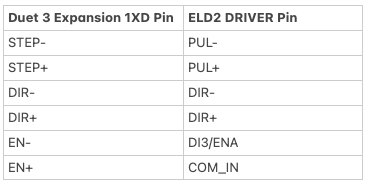
@shauncro Leadshine contacted me and recommended the Differential Connection option wired as follows:
I tried this but it tripped the "Motor speed out of control" alarm right away even before sending a G1 command to turn the servo.
@jay_s_uk I added T5:5:10:10 to the config but I am still receiving the alarm.
-
@code7 can you share the full datasheet for the driver. Thanks
-
@jay_s_uk Here is the full data sheet for the Leadshine ELD2 Driver:
http://leadshineusa.com/UploadFile/Down/ELD2-RS70-- User Manual_2021_Ver1.09.pdf
-
@code7 said in 1XD Closed Loop Servo Setup:
it tripped the "Motor speed out of control" alarm right away even before sending a G1 command to turn the servo.
Wow, this is a pretty sophisticated servo controller. I'd like to know more about it in case I want to use one like it in the future. Can you share some more information about your setup?
- What motor do you have connected?
- What encoder do you have connected?
- Are you configuring it using the RS232 or RS485 serial connection?
- Did Leadshine supply you configuration software for a Windows machine?
There seem to be a lot of things to get right before it's going to move at all, and then tuning the servo controller can get complex, but I think if you go step-by-step you'll get it running.
I've designed servo controllers in the (long ago) past and have used many different types, so I'll try to help as much as I can.
-
@code7 said in 1XD Closed Loop Servo Setup:
I tried this but it tripped the "Motor speed out of control" alarm right away even before sending a G1 command to turn the servo.
Page 67 of your manual says this may be caused by:
- UVW connection error
- Encoder error
Do you know that you have the motor U, V and W wires connected to the correct place on the driver?
Do you know that the encoder is correctly connected to the driver?
Sometimes, the motor has a connector that's perfect and things can't get out-of-order, but I don't know what you've got, so I' apologize if this is a dumb thing for me to ask you.
-
@alankilian Thanks for looking into this. The motor is a Leadshine
ELDM4010V24HL-B5Here is the response from Leadshine: "Motor speed out of control " this Alarm is from 1XD controller.
Please check controller electronic/PPR setting ,make it correspond to servo driver and machine transmission devices.I downloaded the Leadshine software to configure it but am waiting for an RS232 cable to test it out.
I'm using the ELD2 Servo controller.
-
Here's what I would do: (Step 1 of many)
Disconnect the 1XD and connect the motor to the servo controller.
Do not connect anything else to the servo.
Apply power to the servo drive.
What do you get for blinking lights or codes on the servo controller?Send us a photo of the setup.
-
Hey Code,
I have MOVEMENT! But only on the older drivers which are the ACS806
Here's my config
I changed my 1XD to address 20 so configure for your address
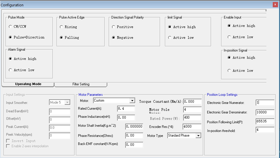
; Drives M569 P20.0 S1 R0 T5:5:5:5 ; physical drive 20.0 goes forwards M569 P0.0 S1 ; physical drive 0.0 goes forwards M569 P0.1 S1 ; physical drive 0.1 goes forwards M569 P0.3 S1 ; physical drive 0.3 goes forwards M584 X20.0 Y0.0 Z0.1 E0.3 ; set drive mapping M350 X16 I0 ; configure microstepping without interpolation M350 Y16 Z16 E16 I1 ; configure microstepping with interpolation M92 X80.00 Y80.00 Z400.00 E420.00 ; set steps per mm M566 X6000.00 Y6000.00 Z60.00 E120.00 ; set maximum instantaneous speed changes (mm/min) M203 X120000.00 Y120000.00 Z180.00 E1200.00 ; set maximum speeds (mm/min) M201 X12000.00 Y12000.00 Z20.00 E250.00 ; set accelerations (mm/s^2) M906 Y300 Z800 E800 I30 ; set motor currents (mA) and motor idle factor in per cent M84 S30 ; Set idle timeout ; Axis Limits M208 X0 Y0 Z0 S1 ; set axis minima M208 X450 Y450 Z450 S0 ; set axis maxima ; Endstops M950 J4 C"!^20.io0.in" ; create input pin number 4 on 1XD board at CAN address 20 for servo alarm. The alarm is active low so invert the input and enable the pullup to prevent spurious alarms caused by noise M950 P5 C"20.io0.out" ; create a GPIO pin number 5 on 1XD board at CAN address 20 for alarm reset M574 X1 J4 S2 ; configure sensorless endstop for low end on X M574 Y1 S3 ; configure sensorless endstop for low end on Y M574 Z1 S2 ; configure Z-probe endstop for low end on Z ; Custom settings are not defined M581 P4 S0 T3 R1 ; invoke trigger 3 when an active-to-inactive edge is detected on input 4 and a file is being printed from SD card This is still testing, so treat as test code. I'm still discovering, I do have to edit the Gear Numerator and Gear Denominator on the driver it self, which means you need your cable, I also had to set a few things in the driver for it to work, not sure what yours will be but here is a pic of what I set to get a few bits of rotation. I need to figure out what the gear denominator and numerator role play in this, also, I need to play with the timing in the config, but hey, it moves with no errors. So I'm chuffed for now.
Wiring for this driver is very different than the eld5 I have, but, I needed the alarm+ and Alarm- connected to IO0.0 out with inverted and pulled up,
Then all the dir+/- Pul+/- and Ena+/- to their corresponding pins, and my settings in the software for the driver are this
I must say that the driver software for the ACS series of drivers is pure K@K. Nothing under the motor parameters saves. And It seems no one in leadshine believes in firmware updates

Will post as I figure out stuff hopefully to help.
-
@shauncro I see my enable motor in the pic is active high, this should be set to low.
But what I find weird, is I only get movement for a 1/4 of the motor, so 50mm to -250mm if I disable motors and turn it to the next pole, I can move with in that pole, but the numbers are different. 50-350 etc currently have my Gear numerator set 1:1 with the denominator. Motor movement is slow though.