Drylin or Not
-
Hi Guy's,
@sonderzugLooking at possibilities of quietening my Tronxy X5SA Pro conversion with either Drylin or Hiwin linear rails.
I've read that the Drylin is most possibly the quietest rail system available, yet a challenge to install.I'm not looking at printing at high temperatures or anything special, I just want to achieve minimal noise compared to the standard tronxy metal rails.
I've contacted Igus and was advised the WS would be the goto. With looking at the WS and finding it was round, I questioned it's use for a coreXY and that I would need 2 for the X axis. The chap from Igus then stated that they also did a square version, the WSQ which have a tolerance of 0.25mm
I've gone back to Igus stating that of the most printers I've seen with the Drylin rail conversions have either gone with the N or T type.
Believe it or not the chap from igus has then stated that, the N or T maybe a better choice for 3d printers!I'd love to here what others have chosen and the difficulies with installingas I'm obviously chasing my tail with asking Igus?
-
@dizzwold In the past i had installed drylin bearings with the hard anodised shafts from IGUS on my ultimaker-style printer. I was never happy with that setup!
It was really hard to have a smooth moving without much play in the printhead.
After half a year printing the wear was high. So i decided to use Misumi linear bearings (with balls). Since then i'm very happy with my setup! -
Thank you for your input.
-
@dizzwold Hi, thanks for reaching out, interesting. May I ask where you're based? (not that I want to run to my colleague and pin them to the wall
 just curious)
When looking at different drylin types, it's important to know what you're doing - designing a new printer or retrofitting an exisiting one.
For designing a new one, drylin W is in fact a good choice, there are carriages that can be adjusted in play which makes it fairly straightforward to set up. It should be the most robust and versatile as well, e.g. the WSX profile offers a lot of options for integrating functions, mounting points etc.
I do not recommend the square WSQ however, since it does have more play but can't be adjusted. I've gone that route with the first version of my DIY printer (pics can be found around here), but have since replaced the drylin alltogether.For retrofitting, I'd not look at drylin W because it seems rather difficult to integrate. I suggest drylin T (replaces ball bearing linear rails 1:1 and many types can be adjusted) or drylin R (replaces round rods and bearings, there are types with minimized tolerances but not 8 or 10 mm diameter as far as I'm aware). Bearing blocks based on R can be 3D printed and made adjustable, for example by using a slotted bushing (can be cut easily) and clamping screws. There is the typical "japan style" bearing + housing that replaces the Misumi style round linear ball bearing, used for example in Prusa printers.
Some things have to be considered:
- sliding bearings with zero play are basically blocks clamped to a rod
 meaning they don't exist. So the (minimal as it can be) play has to be taken into account. In my experience and opinion this doesn't have to be a problem, but can be especially in more dynamic systems. Printers with high velocities and accelerations are (again, IMO) not suited to be equipped with drylin, subject to change. I for one wouldn't equip a Voron with drylin T, for example.
This also has to be considered when replacing Hiwin Style linear bearings, e.g. with drylin T: if you have just one bearing block to support the print head, it will wobble due to play. Two parallel rails should be used to get rid of the wobble. - also, most if not all drylin bearings or systems are susceptible to misalignment and/or torque loads on the bearing, resulting in high wear and friction, probably what @cosmowave was experiencing. This is different in comparison to linear ball bearings. Drylin W guide blocks for example, when bought as a complete unit, mostly have 4 bearing blocks installed to them to alleviate. Translated to our 3D printers this means:
- minimize torque on the bearing, e.g. gantrys have to be driven at both ends/bearing positions. This applies to the x-axis of i3 style printers, and cartesian as well - coreXY when done right should have this effect.
- the fixed/floating bearing princible should be applied, e.g. when two bearing locations are connected by a longer component, one bearing should be fixed and one should have some play. Mark Rehorst aka the digital dentist has some good posts about this on his blog. Seizing due to elevated friction levels can be avoided thus, and aligning parallel rails is more easy because it doesn't have to be perfect.
- in general look at possible over- or underconstrained assemblies, if it is perfectly constrained it should work well with drylin

hope this helps!
- sliding bearings with zero play are basically blocks clamped to a rod
-
also:
in my (personal) opinion, drylin is in fact a very good choice for a quiet machine. If done right as per my above recommendations, that is. The often advertised fact of its rust- and dust-proofness and lack of lubrication make it very easy to maintain, keep clean and in general enjoy. -
@sonderzug
I checked the variants yesterday and my concern isn't about the drylin itself but the surface quality of the rails?
Some look like extruded aluminum, which would eat up drylin in no time, I guess? -
@o_lampe most drylin rails and profiles are hard anodized aluminium (dark brown-grey appearance), the iglidur materials that the gliding elements are offered in are well matched to this. The more "standard" round shafts - iglidur R - are available from Cf53, stainless steel or HC aluminium (amongst others), they might offer better longevity but tbh I'm no expert on that. In general we take good care in testing and selecting the right materials for each application.
Spelling it out I realise that in fact, the ground/polished R rods (Cf53 or stainless) and matching injection molded bushings might be the best option if maximum precision, i.e. minimal play is the goal. However I haven't personally tested this out. Another thing to consider is that the standard bushings require to be press fit into a H7 tolerated bore to achieve the tolerances that are given in the documentation.
-
@sonderzug @cosmowave @o_lampe
Thank you for your input guy's. It's very much appreciated.
@sonderzug I'm in the UK, and basically I'm planning to retrofit the X5SA Pro (CoreXY 330x330x400). Where in the world are you located, It might be a good idea if you could pm me with your contact details?
If I'm going to spend this kind of money, it wants to be correct, not "try these for size, or these ones, oh these ones might be better".The thing that gets me the most with the Drylin T type rails, possibly the most commonly used size, the TS-04-12 is the damned most expensive (just shy of £100 p/m)
But Hey-Ho, and I am kind of sold on the idea of Drylin mainly for the noise reduction, but still open to peoples views.
So you would suggest the T type, and for the Y axis which runs on 2 sides, the 1 side of the Y axis should have a fixed bearing, and the 2nd side should have a floating bearing.
I did read in a post somewhere (I think it might have been in your post regarding "high temp printing"), about using an addition rail to fasten the X axis too, to allow for the 2 Y axis rails/frame to warp slightly with the heat.
I have previously read some of the digital dentist blog posts, but his was a couple of years ago
(didn't he make the Max and the Son of Max, or something similar)? -
I suspect that my post referred to by @sonderzug relates to the X axis construction I used in my sand table called Arrakis. It uses PTFE blocks sliding in t-slot for the Y axis bearings. The Y axis PTFE bearing at one end of the X axis is fixed to the bearing block and the X axis guide rail. At the other end of the X axis the Y axis bearing block has a PTFE bearing mounted on pins and spring loaded so that the X axis doesn't shift along its length between the Y axis rails when the machine is operating.
Post is here: https://drmrehorst.blogspot.com/2021/10/arrakis-this-is-part-of-weirding-way.html
Prior to spring loading the bearing the whole X axis would shift with an audible "klunk" every time the magnet carriage reversed direction along the X axis rail. The problem was that the belt tension was causing the 45 mm square t-slot Y axis rails/frame members to bow, resulting in a loose fit near the center of the table. Spring loading the bearing solved the axis shifting and noise problem.
-
@dizzwold I'm in Cologne, Germany. On one hand, I think these considerations are valuable for everyone thinking about using drylin, on the other hand I want to point out that my suggestions represent my personal opinion and are not to be mistaken for a manufacturer's recommendation (and I'm not knowledgeable enough to acutally present such a one).
I've just now taken a look at the Tronxy printer you mention. No, I don't think drylin T would be the most suited, price is one thing but I'd recommend it as the easiest solution when replacing "Hiwin-Style" (for lack of a better word in our 3D printing universe) linear rails, because they have the same overall mounting dimensions.
Seeing that the Tronxy printer has those "rod-mounted-to-extrusion" style of linear rails with roller bearings, AND they're at the same time a structural component, I'm actually not sure what to do, it seems like a very involved redesign. If I were to choose components to loosely replicate what Tronxy has designed here, I'd go as follows:
- drylin W rails for the y-axis, e.g. left and right (WS-10 single rail). Mounted horizontally. The beauty of this is that you can choose between a range of bearing blocks to match, e.g. with or without (adjustable) pre-tension, or even as a hybrid roller-slider bearing configuration. The rail can be bought without holes, and it could be bored and/or tapped manually to allow mounting of the z-axis rails.
- I recommend two blocks on each side, adjustable on one and standard on the other, this should already fulfill the fixed/floating bearing requirement - seeing that we don't have much elevated temperatures. It should work to repurpose the plates that come with the Tronxy printer.
- the height of the belt arrangement might change, so it might be neccessary to adjust the motor mounts.
- for the x-axis, the easiest and at the same time possibly cheapest and probably still best solution (in terms of precision, play, weight), could be to redesign it entirely, using two parallel 10 mm steel rods (drylin R) and matching bearings.
- these might be, depending on your machining or manufacturing capabilities, bearings that replicate round linear ball bearings with aluminium case, e.g. RE7UM-01 - this should be the easiest solution again. They are available with tighter tolerances or in a split version that's easy to mount (not both, unfortunately - I'd go for precision over ease of maintenance). 3 or 4 such bearings should be used, compare how Prusa does it.
OK, I think that is all I can contribute to this. If you really decide to go down this route, please contact a sales rep at igus UK, if questions arise reference this thread.
@mrehorstdmd (couldn't remember your handle - drmrehorst? digitaldentist? mrehorstdmd it is
 ) thanks for your input, this wasn't the post I was looking for but it should be relevant nonetheless. I was referring to your method of mounting the floating side of the x axis to another bearing block that is fixed to the carriage, a perfect rendition of a fixed/floating setup...
best, Niklas
-
Thank you for your thoughts.
I'm planning on removing the current Y axis rails and fitting with new 2020 extrusion.
The X & Y motors, belts and idlers are all going to have to be repositioned/raised to accommodate a new rail system to some degree anyway.
-
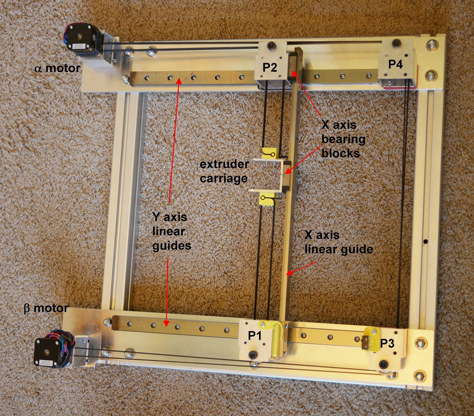
@sonderzug Oh, I see! I did that because I had read reports of people's linear-guide-based corexy printers that would seize up when the temperature in their shop varied a few 10s of degrees. I intended to heat the machine to 50C for printing ABS, so I wanted to ensure the mechanism would keep moving. Here's a photo of the mechanism when I first put it together.

There have been several changes over the last 5 years, but the X axis bearing block at P2 hasn't changed and never will. That extra block allows the Y axis rails to move apart when the machine is heated, which prevents the mechanism from binding.
-
@sonderzug Is there a reason you why you wouldn't go with the T type for the X and Y axis rails?
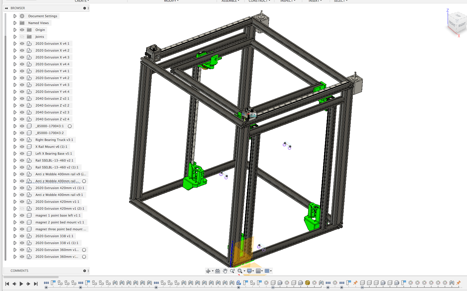
Here's what I'm preposing to do, some of this is from Ed Palisoc/Daivd Husolo (BLV Cube), and the X gantry Mod is from Havoc340 (awaiting his reply to be able to use his mod);
https://www.dropbox.com/s/k5njwtd9fp5njb0/Tronxy Frame v25.f3d?dl=0
-
@Dizzwold Hi, for the y-axis you can probably do this. The TWE-04-12 + TS-04-12 are suitable, and can be adjusted in play. However I'm not 100 % confident that in this configuration, there isn't any rotational play around the x-axis. If you want to use T for the x-axis, I recommend two rails on a 20x20 profile to eliminate play (can be opposite sides or 90° offset, e.g. top and front facing sides of the profile).
Please note that I haven't tested this, which is why I'm a little cautious here...
-
Hi sonderzug,
So for the 2 Y axis rails I would need the 1x, TK-04-12 TWE-1, xxx (no float bearing), and 1x, TK-04-12 TWE-1, xxx, LLY (Y axis float bearing)?
Regarding the X axis Rail. Wouldn't a single rail with a float bearing in the Z axis possibly eliminate any rotation as this could be checked and adjusted when needed?
-
@Dizzwold since the TWE can be adjusted in all directions separately I wouldn't do one floating bearing, but two non-floating. Seeing it's an open frame and the x-axis is probably max. 500-600 mm long, it should work out with the tenths of millimeters of adjustability in the bearing blocks to eliminate binding.
Don't really understand your point about the x-axis rail, my suggestion still stands.
-
Thank you for your advice.
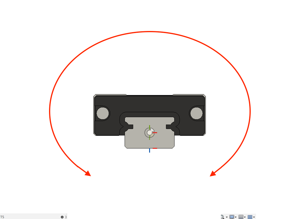
What I was suggesting about the X axis rail is if the possible rotation is like in the image, would the adjustment available in the carriage/bearing block be able to compensate for this?

That is, if I've understood you correctly?
-
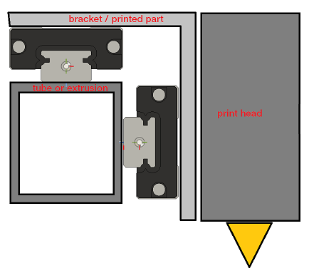
@Dizzwold oh, I see. No, I don't think this rotational play can be eliminated by adjusting the bearing block. The problem is that between its point of rotation and the tip of the nozzle, a minimal amount of play in the bearing will be amplified to become really problematic.
I'd do it like this:

the bracket or printed part can be installed without problems, it doesn't have to have too tight tolerances since the mount is not overconstrained. And wobble in the nozzle is minimized because there is no rotation like in your sketch.
-
Ok. I'm very grateful for your help.