Twin Z axis Motors and MBLA
-
Hi Guys,
FIRMWARE_NAME: RepRapFirmware for Duet 3 MB6HC FIRMWARE_VERSION: 3.4.4 ELECTRONICS: Duet 3 MB6HC v1.01 FIRMWARE_DATE: 2022-10-20 16:19:01
I'm commissioning my 6HC and I've previously been very kindly correct by @jay_s_uk regarding my incorrect use of M671.
I'm converting my Tronxy X5sa Pro with the 6HC. It has 2 Z axis motors halfway in the Y axis and at either end of the X axis. I still have the original heatbed which is basically rolled aluminium with 6 adjusting screw. 4 on each corner and 2 halfway in the X axis front and back. For convenience, let's say I remove the 2 middle adjusters as they only warp things further, and I only have 1 adjuster in each corner.

What I'd done previously, was I was using M671 to check the level in each corner where the 4 adjusting screws are( MBLA), and it would report how much I needed to adjust each corner from the first reference point. @jay_s_uk corrected me on this, as this should be used for where my 2 leadscrews are on my Z axis motors, which it now is.
So although I'm still in the process of commissioning, I'm very green still and learning, doesn't this mean that i now have to manually level each corner with a piece of paper, or is there a way I could implement checking the level of the 4 corners of the bed using MBLA before I run a bed compensation.
I've thought a little and starting looking at maybe a macro, but both the MBLA and bed levelling for independent Z axis motors both use M671, so is this even possible?
If so, in what order should I run things, G32 - Macro (MBLA) - G29, or Macro (MBLA) - G32 - G29?
I'm currently in the process of organising a independent triple Z axis with 8mm cast tool plate, and also looking for advice on magnets and adhesive for the magnets?Config.g
; Configuration file for Duet 3 MB 6HC (firmware version 3.3)
; executed by the firmware on start-up
;
; generated by RepRapFirmware Configuration Tool v3.3.13 on Mon Sep 19 2022 16:04:20 GMT+0100 (British Summer Time)

; General preferences
M575 P1 S1 B57600                                  ; enable support for PanelDue
G90                                                ; send absolute coordinates...
M83                                                ; ...but relative extruder moves
M550 P"Duet 3"                                     ; set printer name
M669 K1                                            ; select CoreXY mode

; Network
M552 P
; Bed Leadscrew Positions
M671 X5:278 Y146:146 P2.0						; middle left, middle right

G4 S1												;wait for expansion boards to start

; Drives
M569 P0.0 S0                                       ; physical drive 0.0 goes backwards
M569 P0.1 S0                                       ; physical drive 0.1 goes backwards
M569 P0.2 S1                                       ; physical drive 0.2 goes forwards
M569 P0.3 S1
M569 P121.0 S0                                       ; physical drive 0.3 goes forwards
M584 X0.0 Y0.1 Z0.2:0.3 E121.0                           ; set drive mapping
M350 X16 Y16 Z16 E16 I1                            ; configure microstepping with interpolation
M92 X80.00 Y80.00 Z400.00 E333.40                  ; set steps per mm
M566 X900.00 Y900.00 Z60.00 E120.00                ; set maximum instantaneous speed changes (mm/min)
M203 X6000.00 Y6000.00 Z180.00 E1200.00            ; set maximum speeds (mm/min)
M201 X500.00 Y500.00 Z20.00 E250.00                ; set accelerations (mm/s^2)
M906 X900 Y900 Z900 E800 I30                       ; set motor currents (mA) and motor idle factor in per cent
M84 S30                                            ; Set idle timeout

; Axis Limits
M208 X-2 Y-8 Z0 S1                                 ; set axis minima
M208 X330 Y330 Z400 S0                             ; set axis maxima

; Endstops
M574 X1 S1 P"!121.io1.in"                              ; configure switch-type (e.g. microswitch) endstop for low end on X via pin !io1.in
M574 Y1 S1 P"!io2.in"                              ; configure switch-type (e.g. microswitch) endstop for low end on Y via pin !io2.in


; Z-Probe
M574 Z1 Z1 S2									   ; set endstops controlled be probe
M558 P8 C"^!121.io0.in" H5 F120 T6000                 ; set Z probe type to switch and the dive height + speeds
G31 P500 X-46 Y-19 Z2.45                            ; set Z probe trigger value, offset and trigger height
M557 X19:244 Y-2:304 P9                           ; define mesh grid

; Heaters
M308 S0 P"temp0" Y"thermistor" T100000 B4138       ; configure sensor 0 as thermistor on pin temp0
M950 H0 C"out0" T0                                 ; create bed heater output on out0 and map it to sensor 0
M307 H0 R0.187 K0.192:0.000 D1.89 E1.35 S1.00 B0   ; disable bang-bang mode for the bed heater and set PWM limit
M140 H0                                            ; map heated bed to heater 0
M143 H0 S120                                       ; set temperature limit for heater 0 to 120C
M308 S1 P"121.temp0" Y"thermistor" T100000 B4138       ; configure sensor 1 as thermistor on pin temp1
M950 H1 C"121.out0" T1                                 ; create nozzle heater output on out1 and map it to sensor 1
M307 H1 R2.498 K0.275:0.349 D6.79 E1.35 S1.00 B0 V24.0  ; disable bang-bang mode for heater  and set PWM limit
M143 H1 S280                                       ; set temperature limit for heater 1 to 280C

; Fans
M950 F0 C"121.out1" Q500                               ; create fan 0 on pin out4 and set its frequency
M106 P0 C"Print Cooler" S0 H-1                     ; set fan 0 name and value. Thermostatic control is turned off
M950 F1 C"121.out2" Q500                               ; create fan 1 on pin out5 and set its frequency
M106 P1 C"Extruder Cooling" S1 H1 T45              ; set fan 1 name and value. Thermostatic control is turned on

; Tools
M563 P0 S"Hemera" D0 H1 F0                         ; define tool 0
G10 P0 X0 Y0 Z0                                    ; set tool 0 axis offsets
G10 P0 R0 S0                                       ; set initial tool 0 active and standby temperatures to 0C

; Custom settings are not defined
; Emergency Stop
M950 J1 C"io4.in"
M851 P1 T0 S0 R0


; Miscellaneous
M911 S10 R11 P"M913 X0 Y0 G91 M83 G1 Z3 E-5 F1000" ; set voltage thresholds and actions to run on power loss

T0

M501
Bed.g
; bed.g ; called to perform automatic bed compensation via G32 ; ; generated by RepRapFirmware Configuration Tool v3.3.13 on Mon Sep 19 2022 16:04:20 GMT+0100 (British Summer Time) ;M561 ; clear any bed transform ;G29 ; probe the bed and enable compensation G28 ; home G30 P0 X5 Y146 Z-9999 ; probe front left G30 P1 X278 Y146 Z-9999 S2 ; probe front right G1 X0 Y0 -
Instead of leaving an adjuster in each corner, see if you can get away with leaving two corners on one side, and one in the middle on the opposite side to make a triangle for a 3 point adjustment. One of those corner points could actually be fixed, and then you only need to adjust the remaining two for tilt and roll. Of course this only makes sense of the bed itself is stiff enough to resist sagging or wild warping if left unsupported like that.
With only 2 motors on either side the best you can do is tilt correction. I don't know what your budget is, or if the frame construction would lend itself to it, but I would either look into removing one motor entirely and use a belt linkage to turn the second side, or add a third motor for actual tilt and roll correction.
@Dizzwold said in Twin Z axis Motors and MBLA:
What I'd done previously, was I was using M671 to check the level in each corner where the 4 adjusting screws are( MBLA), and it would report how much I needed to adjust each corner from the first reference point. @jay_s_uk corrected me on this, as this should be used for where my 2 leadscrews are on my Z axis motors, which it now is.
Technically you can use both. You can get the bed tilt corrected with the motors, and then you can use the method you were using to adjust the bed screws.
Just send the M671 command to set the tilt points for the motors, probe the points and it will auto adjust the motors, and then another to set the points for the adjustment screws and probe those points and manually adjust.
Then on top of that you could use a G29 mesh for the surface irregularities and correct for any remaining tilt/roll.
You can do all of that within bed.g and call it with G32 if you like. Does that make sense?
For reference:
https://docs.duet3d.com/en/User_manual/Connecting_hardware/Z_probe_auto_levellinghttps://docs.duet3d.com/en/User_manual/Connecting_hardware/Z_probe_manual_levelling
@Dizzwold said in Twin Z axis Motors and MBLA:
I'm currently in the process of organising a independent triple Z axis with 8mm cast tool plate
ah, perfect.
-
@Dizzwold for a while I had an FLSun cube, which is a pretty similar setup to what you've got.
I would use a combination of a manual levelling macro to adjust the 4 screws and G32 to initially get it level and then after that G32 was all that was needed.
So I would first adjust the bed so it was set square to the bed frame, i.e. adjust all 4 screws to the same length, then run G32 to get the bed frame level and then the macro for the 4 screws (and adjust until they were all the same) and just run one then the other until it was flat.
this is pretty much my manual levelling macro https://teamgloomy.github.io/useful_macros.html#manual-bed-levelling
The M671 locations are the locations of the 4 screws holding the bed down.
And this is the bed.g (G32) levelling macro I use https://teamgloomy.github.io/useful_macros.html#bedg-file-for-g32 -
Spoilt for choice. Thank you for your advice.
@Phaedrux said in Twin Z axis Motors and MBLA:
ah, perfect.
Yeah, can't wait to extra complexity to something I've not yet mastered.
I've already got the tool plate and a PEI sheet, just perusing my options regarding magnets or not. I don't like the idea of purchasing the tool plate, to then later think "I Wish I had it machined for magnets", after already applying the pei sheet.
It will be along the lines of Ed Palisoc's triple z for the blv, that is when I get printing again.Thank you again.
-
Take a look at the printer in my signature. Rather than use 3 z motors for leveling, it uses a single z motor and 3 lead screws belted to it. The bed plate has 3 point leveling with adjustment screws. Once the screws are adjusted they don't really need a change unless there's been some percussive maintenance. So once manually leveled I run a mesh, and that's it.
Once you have 3 motors, you have to keep them in sync, or re-sync them regularly. A single motor has no such need. Though syncing up the belted lead screws initially can be a bit tricky, since once the belt is on, they all want to move together.
-
@Phaedrux said in Twin Z axis Motors and MBLA:
Take a look at the printer in my signature
That's a good consideration, but for the future. I'm yet to print anything and I hadn't resolved the extruder heating/skipping step issue, so I'm yet to see if that was also linked to the fault I had on the previous board.
I've not printed any of the parts for the 3 triple Z, bed carriers, linear rail attachments etc.I've not read to much on using macros yet, only really glanced at the info, so I'm going to leave that alone for time-being as I just want to get the thing running first.
Sorry @jay_s_uk and thank you for you advice and link to your examples. I will look into this in greater depth once I'm up and running.For the moment, I think I can better grasp @Phaedrux idea of running the 2 together in Bed.g. I've just had a pop at this, but not got it quite correct.
I get the following error;
Bed.g; bed.g ; called to perform automatic bed compensation via G32 ; ; generated by RepRapFirmware Configuration Tool v3.3.13 on Mon Sep 19 2022 16:04:20 GMT+0100 (British Summer Time) ;M561 ; clear any bed transform ;G29 ; probe the bed and enable compensation G28 ; home G30 P0 X5 Y146 Z-9999 ; probe front left G30 P1 X278 Y146 Z-9999 S2 ; probe front right ;G1 X0 Y0 F12000 G28 G30 P0 X5 Y5 Z-9999 ; probe front left G30 P1 X278 Y5 Z-9999 ; probe front right G30 P2 X278 Y302 Z-9999 ; probe rear right G30 P3 X5 Y302 Z-9999 S4 ;probe rear left G1 X0 Y0 F12000I've messed an tweaked around with this. Changed the 2nd set of G30 commands to P2 ,P3 ,P4 & P5, but similar results. Cut-out the middle G1 and add the middle G28.
Should I add another line M671 in config.g for the 2nd set, the adjuster screws under the leadscrew positions?Config.g
; Configuration file for Duet 3 MB 6HC (firmware version 3.3)
; executed by the firmware on start-up
;
; generated by RepRapFirmware Configuration Tool v3.3.13 on Mon Sep 19 2022 16:04:20 GMT+0100 (British Summer Time)

; General preferences
M575 P1 S1 B57600                                  ; enable support for PanelDue
G90                                                ; send absolute coordinates...
M83                                                ; ...but relative extruder moves
M550 P"Duet 3"                                     ; set printer name
M669 K1                                            ; select CoreXY mode

; Network
M552 Pxxx.xxx.xxx.xxx
; Bed Leadscrew Positions
M671 X5:278 Y146:146 P2.0 X5:278:278:5 Y5:5:302:302 P0.5						; middle left, middle right

G4 S1												;wait for expansion boards to start

; Drives
M569 P0.0 S0                                       ; physical drive 0.0 goes backwards
M569 P0.1 S0                                       ; physical drive 0.1 goes backwards
M569 P0.2 S1                                       ; physical drive 0.2 goes forwards
M569 P0.3 S1
M569 P121.0 S0                                       ; physical drive 0.3 goes forwards
M584 X0.0 Y0.1 Z0.2:0.3 E121.0                           ; set drive mapping
M350 X16 Y16 Z16 E16 I1                            ; configure microstepping with interpolation
M92 X80.00 Y80.00 Z400.00 E333.40                  ; set steps per mm
M566 X900.00 Y900.00 Z60.00 E120.00                ; set maximum instantaneous speed changes (mm/min)
M203 X6000.00 Y6000.00 Z180.00 E1200.00            ; set maximum speeds (mm/min)
M201 X500.00 Y500.00 Z20.00 E250.00                ; set accelerations (mm/s^2)
M906 X900 Y900 Z900 E800 I30                       ; set motor currents (mA) and motor idle factor in per cent
M84 S30                                            ; Set idle timeout

; Axis Limits
M208 X-2 Y-8 Z0 S1                                 ; set axis minima
M208 X330 Y330 Z400 S0                             ; set axis maxima

; Endstops
M574 X1 S1 P"!121.io1.in"                              ; configure switch-type (e.g. microswitch) endstop for low end on X via pin !io1.in
M574 Y1 S1 P"!io2.in"                              ; configure switch-type (e.g. microswitch) endstop for low end on Y via pin !io2.in


; Z-Probe
M574 Z1 Z1 S2									   ; set endstops controlled be probe
M558 P8 C"^!121.io0.in" H5 F120 T6000                 ; set Z probe type to switch and the dive height + speeds
G31 P500 X-46 Y-19 Z2.45                            ; set Z probe trigger value, offset and trigger height
M557 X19:244 Y-2:304 P9                           ; define mesh grid

; Heaters
M308 S0 P"temp0" Y"thermistor" T100000 B4138       ; configure sensor 0 as thermistor on pin temp0
M950 H0 C"out0" T0                                 ; create bed heater output on out0 and map it to sensor 0
M307 H0 R0.187 K0.192:0.000 D1.89 E1.35 S1.00 B0   ; disable bang-bang mode for the bed heater and set PWM limit
M140 H0                                            ; map heated bed to heater 0
M143 H0 S120                                       ; set temperature limit for heater 0 to 120C
M308 S1 P"121.temp0" Y"thermistor" T100000 B4138       ; configure sensor 1 as thermistor on pin temp1
M950 H1 C"121.out0" T1                                 ; create nozzle heater output on out1 and map it to sensor 1
M307 H1 R2.498 K0.275:0.349 D6.79 E1.35 S1.00 B0 V24.0  ; disable bang-bang mode for heater  and set PWM limit
M143 H1 S280                                       ; set temperature limit for heater 1 to 280C

; Fans
M950 F0 C"121.out1" Q500                               ; create fan 0 on pin out4 and set its frequency
M106 P0 C"Print Cooler" S0 H-1                     ; set fan 0 name and value. Thermostatic control is turned off
M950 F1 C"121.out2" Q500                               ; create fan 1 on pin out5 and set its frequency
M106 P1 C"Extruder Cooling" S1 H1 T45              ; set fan 1 name and value. Thermostatic control is turned on

; Tools
M563 P0 S"Hemera" D0 H1 F0                         ; define tool 0
G10 P0 X0 Y0 Z0                                    ; set tool 0 axis offsets
G10 P0 R0 S0                                       ; set initial tool 0 active and standby temperatures to 0C

; Custom settings are not defined
; Emergency Stop
M950 J1 C"io4.in"
M851 P1 T0 S0 R0


; Miscellaneous
M911 S10 R11 P"M913 X0 Y0 G91 M83 G1 Z3 E-5 F1000" ; set voltage thresholds and actions to run on power loss

T0

M501
How can I resolve this. If I remove the S2 and changed the S4 to S6, then surely it won't report and adjust the leadscrews?
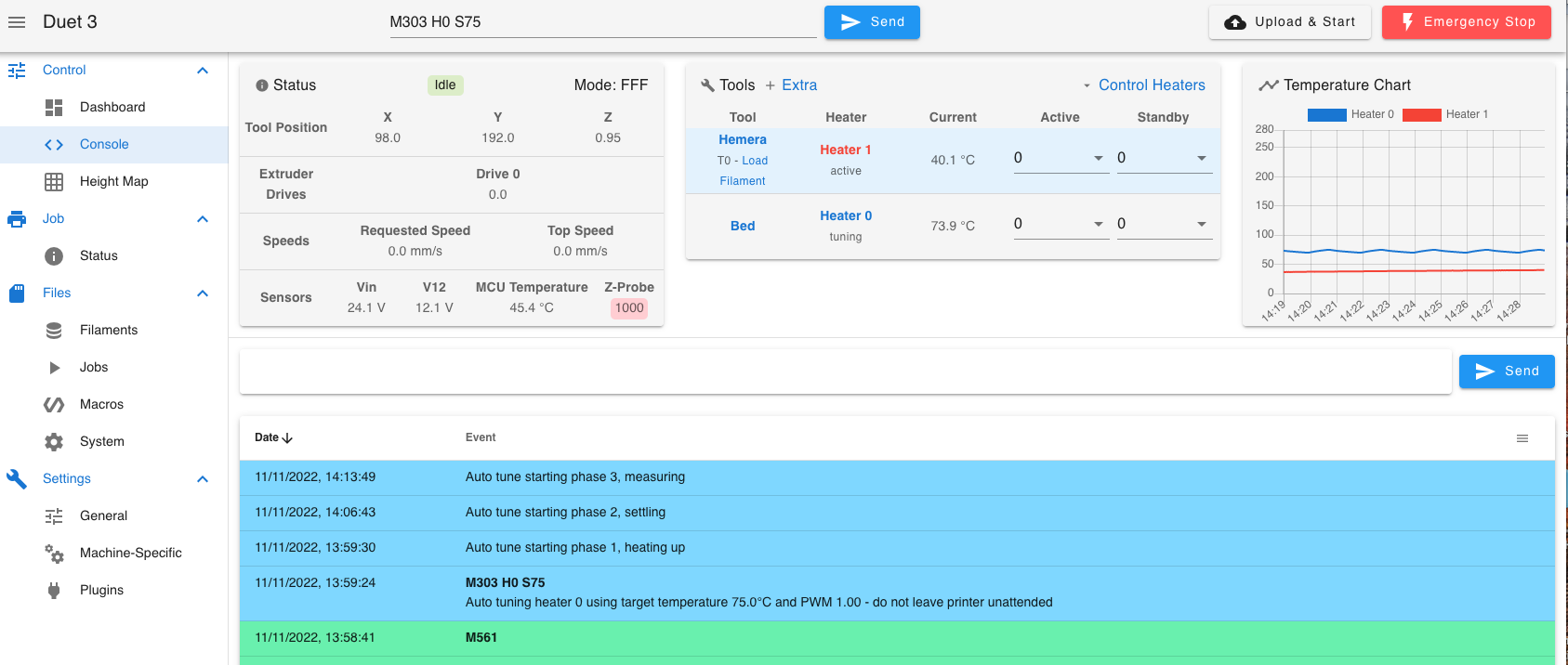
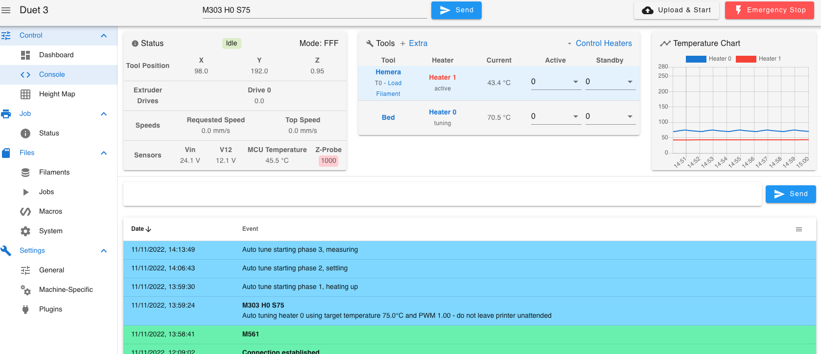
I also had a warning response after doing a bed pid, but I'd cleared the console before taking a screenshot. I've had a look to see if I can find somekind of log to recover this warning but I don't see anything to do so?
Looks Like I'll have to pid the bed again, when I've took the dog out. -
Hi Guys,
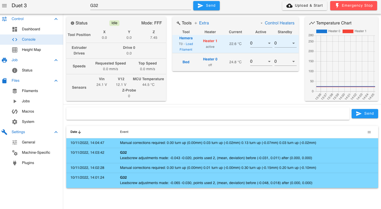
I had just written a reply stating that I still hadn't quite figured it out, but I think I've kind-of grasp both your ideas, although they need tidying up they both work;
Bed.g
; bed.g
; called to perform automatic bed compensation via G32
;
; generated by RepRapFirmware Configuration Tool v3.3.13 on Mon Sep 19 2022 16:04:20 GMT+0100 (British Summer Time)
;M561 ; clear any bed transform
;G29  ; probe the bed and enable compensation
M671  X5:278 Y146:146 P2.0
G28			; home
G30 P0 X5 Y146 Z-9999				; probe front left
G30 P1 X278 Y146 Z-9999	S2		; probe front right
G1  X0 Y0 F12000
;G28
M671 X5:278:278:5 Y5:5:302:302 P0.5
G28
G30 P0 X5 Y5 Z-9999				; probe front left
G30 P1 X278 Y5 Z-9999			; probe front right
G30 P2 X278 Y302 Z-9999			; probe rear right
G30 P3 X5 Y302 Z-9999 S4  		 ;probe rear left
G1  X0 Y0 F12000
Config.g
; Configuration file for Duet 3 MB 6HC (firmware version 3.3)
; executed by the firmware on start-up
;
; generated by RepRapFirmware Configuration Tool v3.3.13 on Mon Sep 19 2022 16:04:20 GMT+0100 (British Summer Time)

; General preferences
M575 P1 S1 B57600                                  ; enable support for PanelDue
G90                                                ; send absolute coordinates...
M83                                                ; ...but relative extruder moves
M550 P"Duet 3"                                     ; set printer name
M669 K1                                            ; select CoreXY mode

; Network
M552 Pxxx.xxx.xxx.xxx

; Bed Leadscrew Positions
M671 X5:278 Y146:146 P2.0						; middle left, middle right
M671 X5:278:278:5 Y5:5:302:302 P0.5

G4 S1												;wait for expansion boards to start

; Drives
M569 P0.0 S0                                       ; physical drive 0.0 goes backwards
M569 P0.1 S0                                       ; physical drive 0.1 goes backwards
M569 P0.2 S1                                       ; physical drive 0.2 goes forwards
M569 P0.3 S1
M569 P121.0 S0                                       ; physical drive 0.3 goes forwards
M584 X0.0 Y0.1 Z0.2:0.3 E121.0                           ; set drive mapping
M350 X16 Y16 Z16 E16 I1                            ; configure microstepping with interpolation
M92 X80.00 Y80.00 Z400.00 E333.40                  ; set steps per mm
M566 X900.00 Y900.00 Z60.00 E120.00                ; set maximum instantaneous speed changes (mm/min)
M203 X6000.00 Y6000.00 Z180.00 E1200.00            ; set maximum speeds (mm/min)
M201 X500.00 Y500.00 Z20.00 E250.00                ; set accelerations (mm/s^2)
M906 X900 Y900 Z900 E800 I30                       ; set motor currents (mA) and motor idle factor in per cent
M84 S30                                            ; Set idle timeout

; Axis Limits
M208 X-2 Y-8 Z0 S1                                 ; set axis minima
M208 X330 Y330 Z400 S0                             ; set axis maxima

; Endstops
M574 X1 S1 P"!121.io1.in"                              ; configure switch-type (e.g. microswitch) endstop for low end on X via pin !io1.in
M574 Y1 S1 P"!io2.in"                              ; configure switch-type (e.g. microswitch) endstop for low end on Y via pin !io2.in


; Z-Probe
M574 Z1 Z1 S2									   ; set endstops controlled be probe
M558 P8 C"^!121.io0.in" H5 F120 T6000                 ; set Z probe type to switch and the dive height + speeds
G31 P500 X-46 Y-19 Z2.45                            ; set Z probe trigger value, offset and trigger height
M557 X19:244 Y-2:304 P9                           ; define mesh grid

; Heaters
M308 S0 P"temp0" Y"thermistor" T100000 B4138       ; configure sensor 0 as thermistor on pin temp0
M950 H0 C"out0" T0                                 ; create bed heater output on out0 and map it to sensor 0
M307 H0 R0.187 K0.192:0.000 D1.89 E1.35 S1.00 B0   ; disable bang-bang mode for the bed heater and set PWM limit
M140 H0                                            ; map heated bed to heater 0
M143 H0 S120                                       ; set temperature limit for heater 0 to 120C
M308 S1 P"121.temp0" Y"thermistor" T100000 B4138       ; configure sensor 1 as thermistor on pin temp1
M950 H1 C"121.out0" T1                                 ; create nozzle heater output on out1 and map it to sensor 1
M307 H1 R2.498 K0.275:0.349 D6.79 E1.35 S1.00 B0 V24.0  ; disable bang-bang mode for heater  and set PWM limit
M143 H1 S280                                       ; set temperature limit for heater 1 to 280C

; Fans
M950 F0 C"121.out1" Q500                               ; create fan 0 on pin out4 and set its frequency
M106 P0 C"Print Cooler" S0 H-1                     ; set fan 0 name and value. Thermostatic control is turned off
M950 F1 C"121.out2" Q500                               ; create fan 1 on pin out5 and set its frequency
M106 P1 C"Extruder Cooling" S1 H1 T45              ; set fan 1 name and value. Thermostatic control is turned on

; Tools
M563 P0 S"Hemera" D0 H1 F0                         ; define tool 0
G10 P0 X0 Y0 Z0                                    ; set tool 0 axis offsets
G10 P0 R0 S0                                       ; set initial tool 0 active and standby temperatures to 0C

; Custom settings are not defined
; Emergency Stop
M950 J1 C"io4.in"
M851 P1 T0 S0 R0


; Miscellaneous
M911 S10 R11 P"M913 X0 Y0 G91 M83 G1 Z3 E-5 F1000" ; set voltage thresholds and actions to run on power loss

T0

M501
*Nb, I've omited
M98 P"Bed_Adjusting_Screws.g"from bed.g.
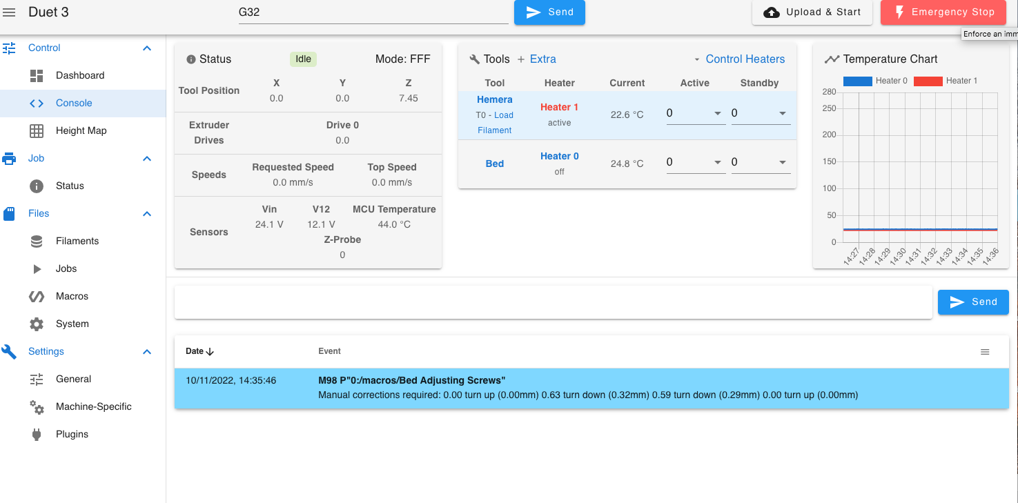
Bed Adjusting Screw MacroG28 M671 X5:278:278:5 Y5:5:302:302 P0.5 G30 P0 X5 Y5 Z-9999 ; probe front left G30 P1 X278 Y5 Z-9999 ; probe front right G30 P2 X278 Y302 Z-9999 ; probe rear right G30 P3 X5 Y302 Z-9999 S4 ;probe rear left G1 X0 Y0 F12000So it looks like I've learnt more than I even expected today.
Now I'll try the bed pid again...
Thank you both again for your help, I'm really grateful. You have the patience of saint's.
-
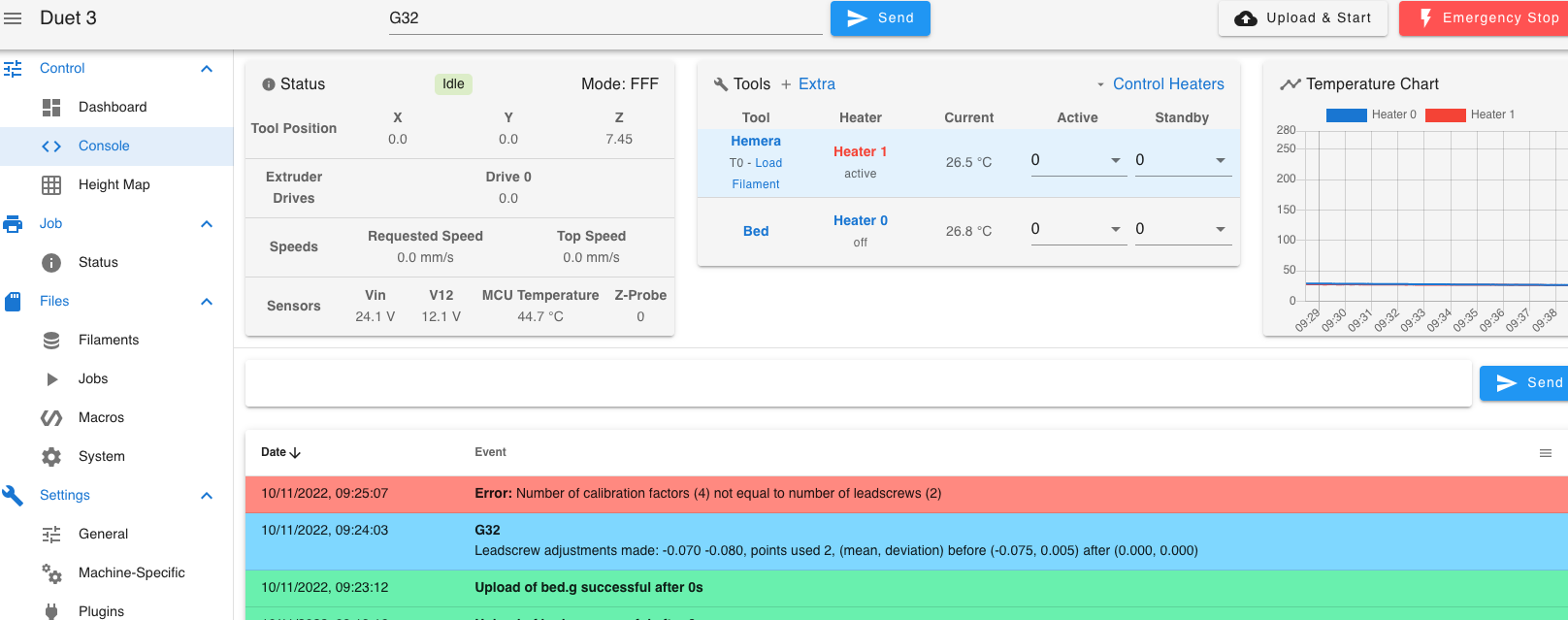
Yes I think you've got it.
-
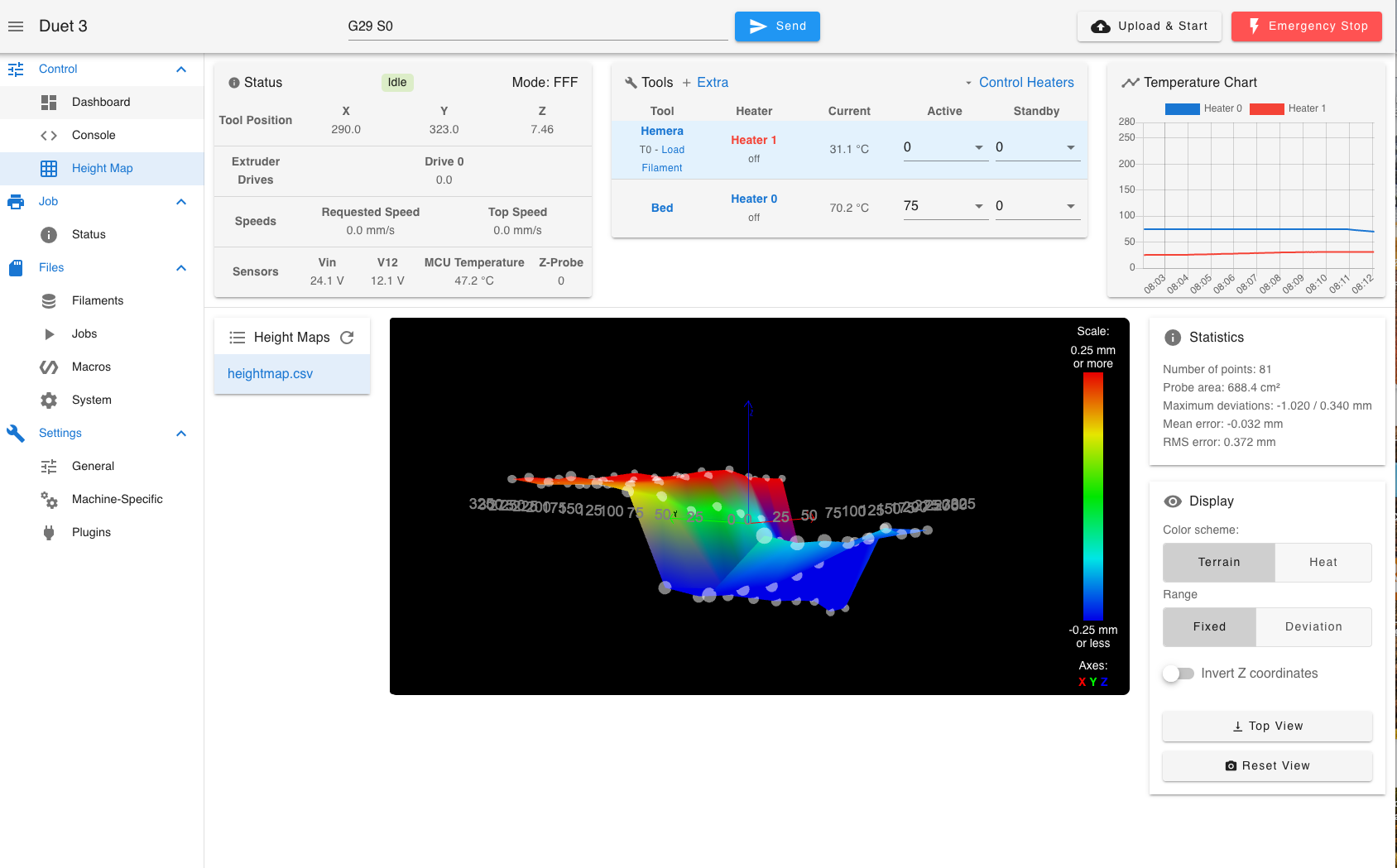
Hm, Maybe I don't or there is something else a-miss. In the 1st image everything looks fine, but in the 2nd image everything gone pear shaped;
-
 undefined Dizzwold referenced this topic
-
@Dizzwold can you run G32 again before you run G29?
that is a decent dip in the bed though.
If you put a straight edge on the bed along the X axis can you see anything like the 1mm dip its showing?
What type of probe are you using? -
I'm waiting for the bed to cool down and do another PID tune.
The bed is the original Tronxy 300 x330 (rolled Alloy) with the Tronxy TR Glass Sensor (Z probe), Inductive NPN with the Glass Bed that comes with the Probe;
https://www.tronxy3d.com/products/tronxy-black-tr-auto-leveling-sensor-lattice-glass-plate-500-500mm
It's usually quite reliable IMO, and even with the faulty board previously, it was never this off. -
Is there a way to run a log while running the bed pid, G32, G29?
-
@jay_s_uk
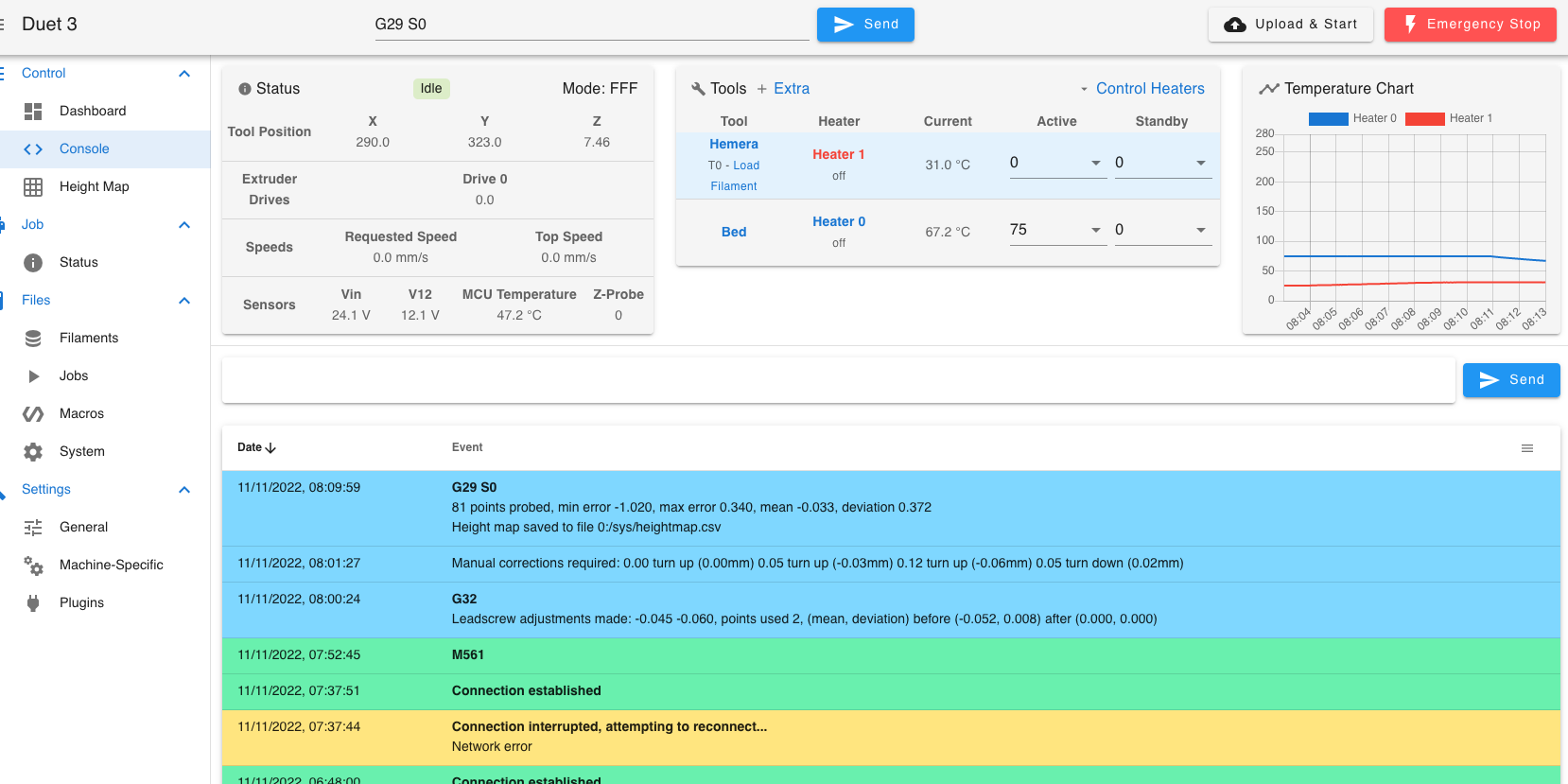
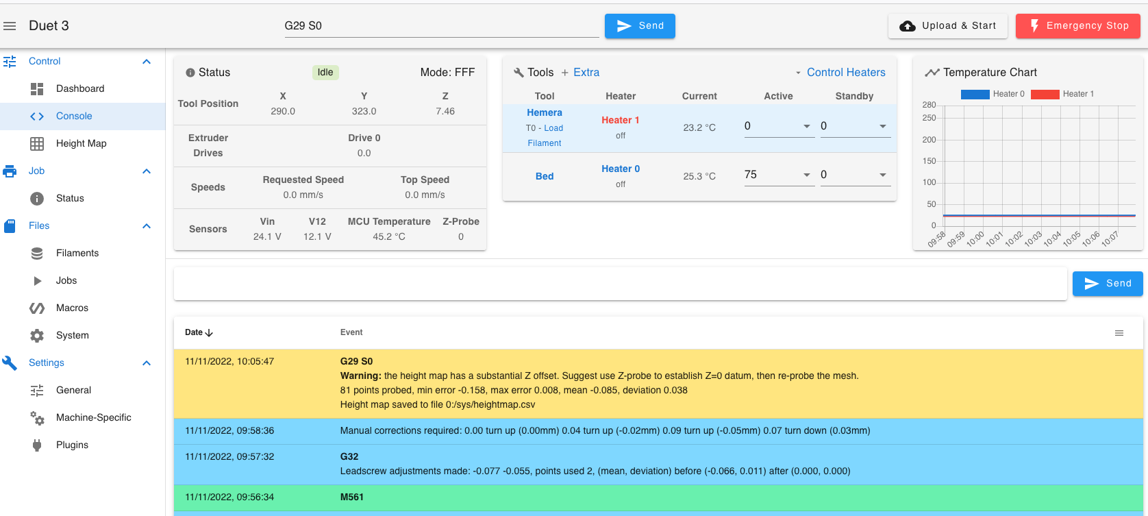
Okay, I've just done, with a Cold bed and nozzle M561, G32, G29, and got the following results. I've left the machine powered on over night thinking that the motors (Z axis) would hold position, but with the result it would look like this isn't the case. So I reset the Z=0 (G92 Z0, G30 S-1), and try again;
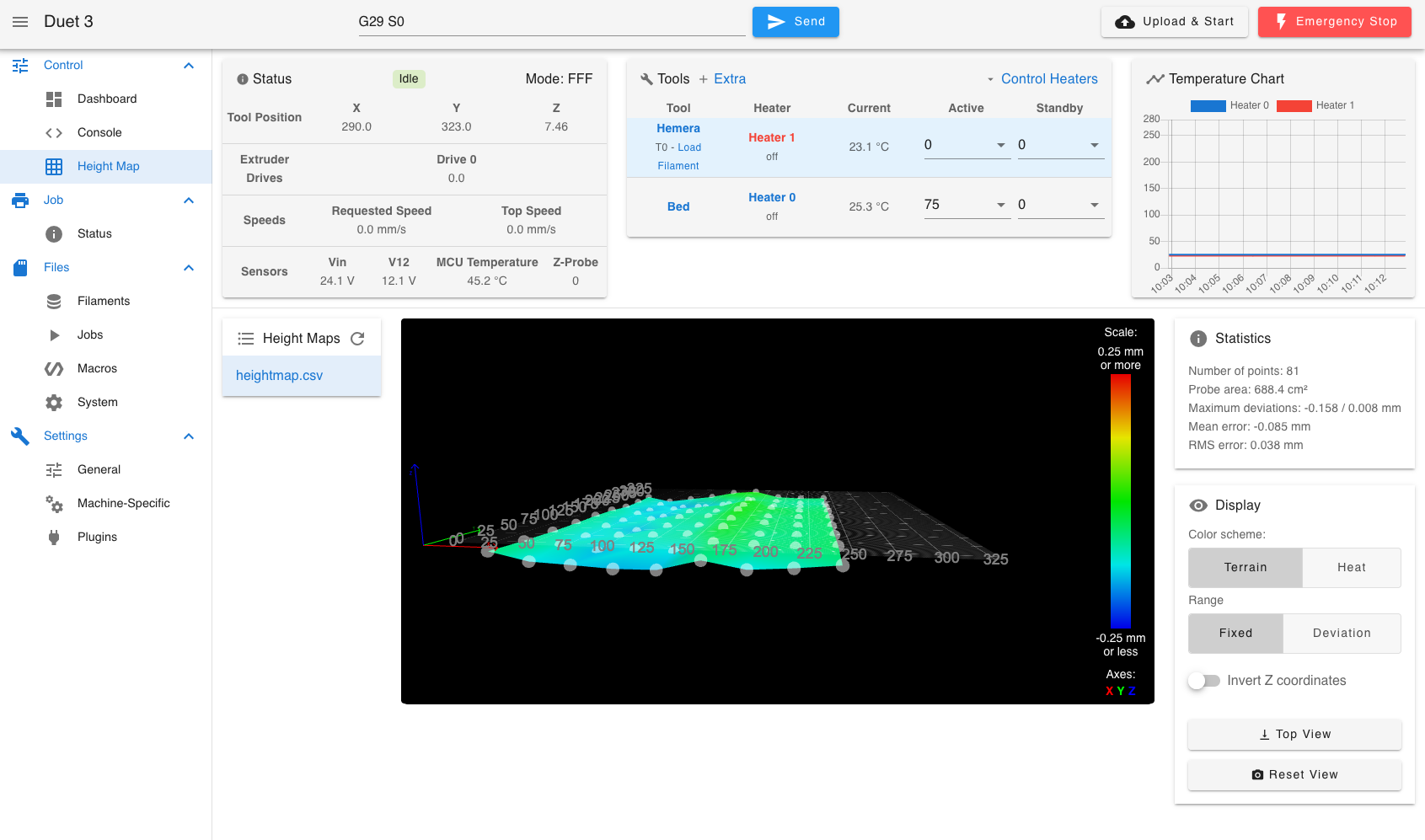
Yet, I now have this for the height map???
-
@Dizzwold It's a bit hard to see if that step is in the X or Y axis. If it is in the Y axis so the first half of the entire probe is one level and the second half is another, then that may be due to lost steps in Z movement. If the step is in X, so that it happens as the head scans left/right then I'd be checking that nothing is "pulling on the print head" like a bowden tube or wiring and causing movement.
-
Hi,
Oh dogs balls, that could be my hotend cable chain, rather the nylon cable braid around it.
The idea of the cable braiding was to stop the cable chain inverting inwards and blocking the path of the carriage.


-
@jay_s_uk @gloomyandy @Phaedrux
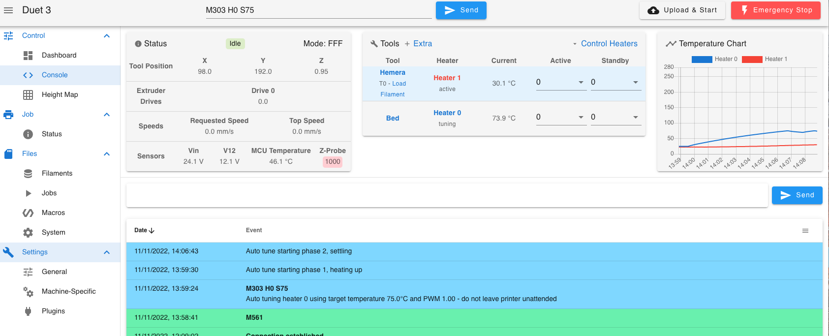
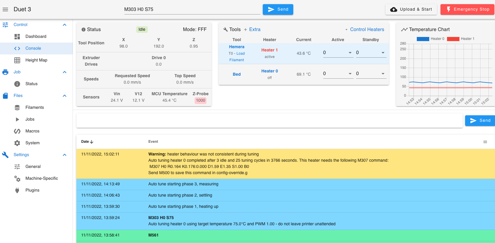
I've done another Bed PID, and got a similar warning message.
The graph raised and fell between 69.9 and 75.1;

-
If you save those values and use them are you able to set a temp for the bed and have it reach it and maintain it?
-
For the bed, just about. I don't think it will go much higher than that, bearing in mind this is the stock Tronxy heater and bed.
Cant wait to get the parts printed for the cast tool plate.
I was having a problem that now I'm printing, that I was having to add around 0.5mm in babysteps.
I've figured out why this was.
I was setting Z Probe height with G31 in config.g with the Tool position /nozzle height shown, hence to 0.5mm. -
@Dizzwold said in Twin Z axis Motors and MBLA:
Tronxy heater and bed.
Well 70c for that bed heater is probably the limit.