CAN bus and Toolboard 1LC Connection Issues
-
This is related to my previous topic:
https://forum.duet3d.com/topic/30919/duet-3-mini-5-with-multiple-toolboards-1lc?_=1672498609875I cannot connect to my new toolboard. Here is the series of events:
Yesterday the i successfully installed and connected to the new toolboard. I changed its address from 121 to 21, and my original toolboard i changed its address to 20. I successfully powered up both IDEX print heads and did a hotend test up to temperature. both thermistors and heaters worked and they appeared in DWC normally.
During the first cycle up to 220C, suddenly both toolboards lose connection, the temperatures show 2000C, and all fans spin up to maximum. this is usually an indication that grounding was lost somewhere, or the toolboards lost communication. multiple attempts to power on yielded same result, no communication and fast flashing red LED.
i checked all wiring and could not find any problems, so i shut down the printer overnight.
This morning i continue, turn on the printer, and both toolboards work normally. the issue is gone, so this time i do a startup test but i isolate variables. i first turn on my old 1LC to 220C and it turns on fine. i turn off the heater, and turn on the new 1LC heater to 220C. it reaches 220C, fan is on, but after about 1 minute both toolboards lose connection, 2000C, fans spin up maximum.
so using terminal YAT i can successfully connect to the old toolboard and its on firmware v3.4.2. but i cannot connect to the new toolboard. if i remove all wiring and simply connect the Duet 3 Mini 5+ with USB, connect the new toolboard to 24V power and the CAN wire, i can not connect. it gives timeout error.
but when it was new this board did connect successfully during first bootup.
EDIT: new toolboard firmware is v3.3.
both toolboards have bootloader v2.3.
-
@RogerPodacter from troubleshooting, it seems like one portion of my CAN wiring is weak. if i swapp connections, the new toolboard suddenly works and the old toolboard does not. so something is wrong with my CAN wiring but i'm not sure what.
I wire from the Duet 3 Mini 5+ to toolboard 2, then toolboard 2 over to toolboard 1.
-
@RogerPodacter more info, it doesnt seem to be the wiring, but something between the 2 toolboards. if i directly connect each board to the mainboard, each works normally. but only when i wire the toolboards in CAN series is when only 1 works but not the other. i'm very confused.
-
@RogerPodacter A couple of possibilities...
- Does the power supply you are using have the capacity for two boards with active heaters?
- Perhaps the wiring setup you are using (https://forum.duet3d.com/topic/30919/duet-3-mini-5-with-multiple-toolboards-1lc/3?_=1671973616337) is causing some sort of problem.
-
@gloomyandy I considered my power supply which is a Meanwell 200 Watt 24V. but i dont suspect it is the cause, but i dont know how to determine that. the PSU is still working normally.
if i starved the system of power, would that fry a board component? visually looking at the boards they are all fine.
i suspect its related to the termination resistor, and which connector i am using. is there a different between CANBUS 1 and 3, or 2 and 4, as long as i pair L to L and H to H?
-
@RogerPodacter to add more details, if i simplify everything and simply take my new toolboard connected to the mainboard, i get no connection if i use the 3 and 4 CAN, but connecting to 1 and 2 gives a solid connection.
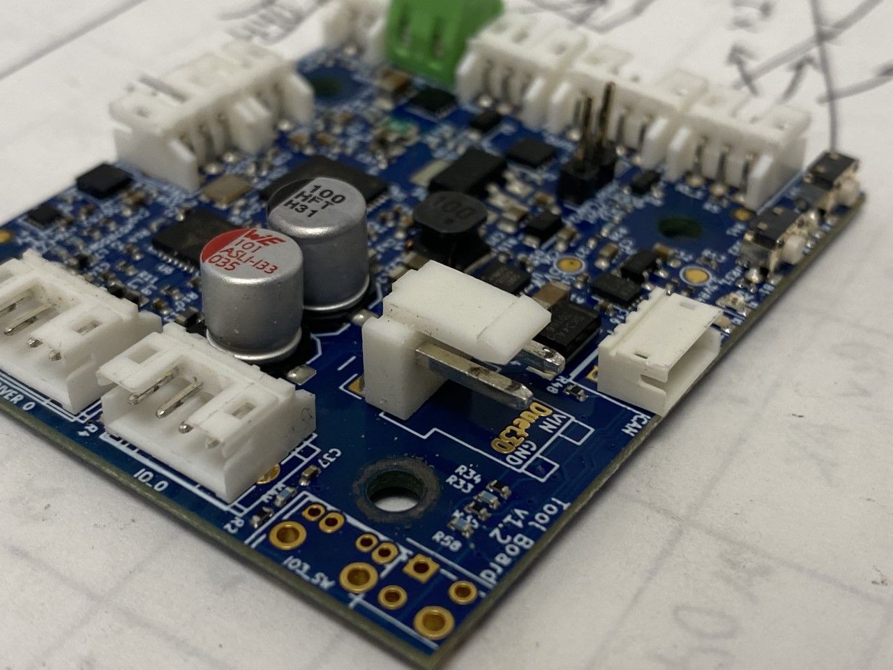
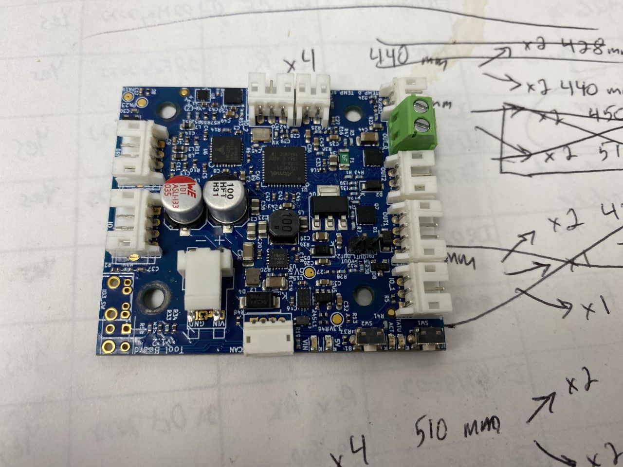
on the ending toolboard, i have the pads soldered which incorporates the 120 ohm resistor. so i am using 3 and 4 connectors.
-
@RogerPodacter said in CAN bus and Toolboard 1LC Connection Issues:
if i directly connect each board to the mainboard, each works normally
Are you able to get the toolboard firmwares updated to match the mainboard when directly connected?
-
@Phaedrux yes i did upgrade so now both toolboards are on 3.4.2 firmware.
all i can think is i somehow damaged one of the boards. under the microscope i see no damage anywhere, specifically the CAN bus and controller chip. BUT, the original toolboard has some minor black charred on the metal power connector when i remove the power connector. its been in use for months so perhaps its from prolonged use.
so right now it looks like only one side of the CAN bus seems to work. both toolboards work if i plug directly into the mainboard, using CAN 3 and 4. but putting any of them in series using CAN 1 and 2, simply no communication.
my 200 watt Meanwell PSU is underpowered to run 2 toolboards pulling 5A each. so maybe that is the cause...
EDIT: i am using 60w heaters so my current draw would be 2.5A at 24V maximum per toolhead, so i doubt it could be related to power levels.
-
@RogerPodacter Does this look damaged/blackened power connection?
-
@RogerPodacter I am stumped. here is M122 from each toolboard.
Original 1LC
12/31/2022, 2:02:09 PM 	M122 B20
Diagnostics for board 20:
Duet TOOL1LC rev 1.1 or later firmware version 3.4.2 (2022-09-13 15:06:56)
Bootloader ID: SAMC21 bootloader version 2.3 (2021-01-26b1)
All averaging filters OK
Never used RAM 3044, free system stack 88 words
Tasks: Move(notifyWait,0.0%,153) HEAT(notifyWait,0.1%,99) CanAsync(notifyWait,0.0%,65) CanRecv(notifyWait,0.0%,76) CanClock(notifyWait,0.0%,65) ACCEL(notifyWait,0.0%,61) TMC(notifyWait,3.0%,57) MAIN(running,92.0%,441) IDLE(ready,0.0%,26) AIN(delaying,4.9%,142), total 100.0%
Last reset 00:04:25 ago, cause: power up
Last software reset data not available
Driver 0: pos 0, 80.0 steps/mm,standstill, SG min 0, read errors 0, write errors 0, ifcnt 9, reads 1499, writes 9, timeouts 0, DMA errors 0, CC errors 0, steps req 0 done 0
Moves scheduled 0, completed 0, in progress 0, hiccups 0, step errors 0, maxPrep 0, maxOverdue 0, maxInc 0, mcErrs 0, gcmErrs 0
Peak sync jitter -2/6, peak Rx sync delay 194, resyncs 0/0, no step interrupt scheduled
VIN voltage: min 7.1, current 24.1, max 24.1
MCU temperature: min 22.5C, current 35.2C, max 35.3C
Last sensors broadcast 0x00000000 found 0 18 ticks ago, 0 ordering errs, loop time 0
CAN messages queued 2148, send timeouts 206, received 336, lost 0, free buffers 37, min 37, error reg 610000
Last cancelled message type 4519 dest 0
dup 0, oos 0/0/0/0, bm 0, wbm 0, rxMotionDelay 0
Accelerometer: LIS3DH, status: 00
I2C bus errors 0, naks 3, other errors 0
New 1LC
12/31/2022, 2:00:31 PM M122 B21 Diagnostics for board 21: Duet TOOL1LC rev 1.1 or later firmware version 3.4.2 (2022-09-13 15:06:56) Bootloader ID: SAMC21 bootloader version 2.3 (2021-01-26b1) All averaging filters OK Never used RAM 2624, free system stack 88 words Tasks: Move(notifyWait,0.0%,153) HEAT(notifyWait,0.1%,113) CanAsync(notifyWait,0.0%,65) CanRecv(notifyWait,0.0%,76) CanClock(notifyWait,0.0%,65) ACCEL(notifyWait,0.0%,61) TMC(delaying,3.0%,57) MAIN(running,92.0%,351) IDLE(ready,0.0%,26) AIN(delaying,4.9%,148), total 100.0% Last reset 00:02:48 ago, cause: power up Last software reset data not available Driver 0: pos 0, 400.0 steps/mm,standstill, SG min 0, read errors 0, write errors 0, ifcnt 14, reads 18239, writes 14, timeouts 0, DMA errors 0, CC errors 0, steps req 0 done 0 Moves scheduled 0, completed 0, in progress 0, hiccups 0, step errors 0, maxPrep 0, maxOverdue 0, maxInc 0, mcErrs 0, gcmErrs 0 Peak sync jitter -2/10, peak Rx sync delay 186, resyncs 1/0, no step interrupt scheduled VIN voltage: min 7.1, current 24.3, max 24.3 MCU temperature: min 22.1C, current 27.3C, max 27.3C Last sensors broadcast 0x00000008 found 1 197 ticks ago, 0 ordering errs, loop time 0 CAN messages queued 3200, send timeouts 22, received 854, lost 0, free buffers 37, min 37, error reg ff0000 Last cancelled message type 4519 dest 0 dup 0, oos 0/0/0/0, bm 0, wbm 0, rxMotionDelay 0 Accelerometer: LIS3DH, status: 00 I2C bus errors 0, naks 3, other errors 0 -
@RogerPodacter Apologies, please close this thread as resolved. the entire time the CAN connection was lose. the factory one ironically. once i recrimped it, everything works normally. it was just coincidental timing, the carriage motion must have loosened it up.
-
 undefined Phaedrux marked this topic as a question
-
undefined Phaedrux has marked this topic as solved
-
@RogerPodacter I am glad you solved it. I suspect my toolchanger has a similar problem because the wiring to one of the tool boards does not pass the CAN bus through. For now I have used the jumpers on the tool distribution board to provide a bypass, but this isn't ideal.