X,Y Hall Effect Endstop Sensor Wiring & Config Question
-
Hello to all,
I have searched for several hours to find the answers and come up short. The machine is Voron 2.4 / 350, running Duet 6HC and 3HC expansion with the latest firmware updated DWC on a pi SBC.
I would like to know the correct config for setting up Voron Hall Effect XY Endstop PCB. I have used a volt meter and can confirm the wiring is correct, getting 5V to the board and correct io pins per below wiring diagram from the 6HC board to Hall Effect PCB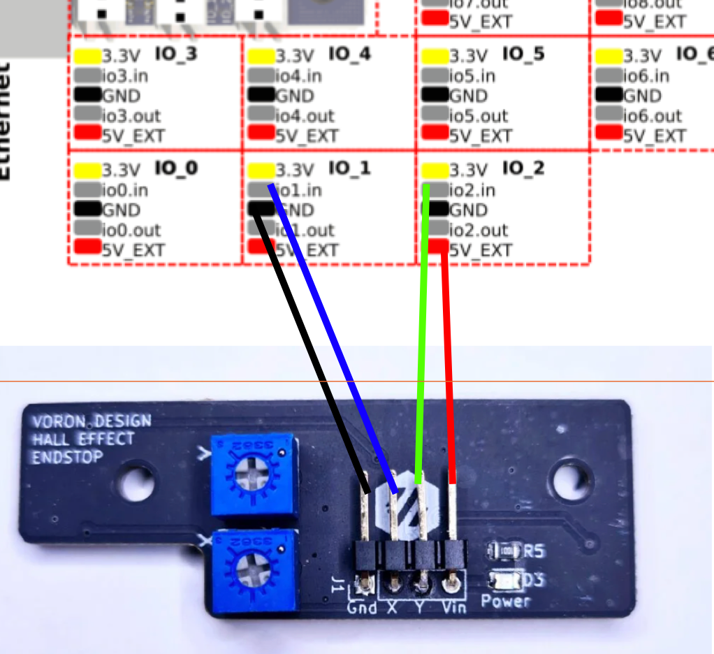
Regarding the config of Hall Effect Sensors, what is the correct S- value? I am assuming a switch = S1?
; Endstops
M574 X2 S1 P"io1.in"
M574 Y2 S1 P"io2.in"
M574 Z2 S1 P"io3.in"
Calling M119 returns = Endstops - X: at max stop, Y: at max stop, Z: at max stop, Z probe: at min stop
If this is correct then I am failing to see X and Y change when triggered with magnets.
Any help is appreciated - thanks in advance
-
S1 is the only valid option. If you need to invert the trigger signal, you would add a
!to the pin name. likeM574 Y2 S1 P"!io2.in"However, it sounds like you're never getting the status of the endstop to change even when it should be?
Have you seen the hall sensor notes here? https://docs.duet3d.com/en/User_manual/Connecting_hardware/Sensors_endstops#h-33v-compatible-hall-sensor
-
@Phaedrux only barely related, but would it also be possible to use IO2.out as an input for X to keep IO1 free?
-
@oliof that would work fine to keep everything on 1 header.
@KCMARINE if this is a new build voron I would ditch the hall effect endstops as it seems generally accepted that they aren't great in enclosures and tend to suffer from repeatability issues. From what I've seen on discord, most users have changed to microswitch endstops.
-
Thanks for the confirmation and advice. I changed to micro switches, and it is working great - the hall effect sensor board seems defective.
Appreciate your support - thanks, Ken -
 undefined Phaedrux marked this topic as a question
-
undefined Phaedrux has marked this topic as solved