Linear Rail X Gantry Support (MGN12)
-
Hi Guys,
A quick couple of questions.
I read previously that it's not a good idea to use a MGN12 Linear Rail to solely be it's own X axis gantry and really need supporting.
If I've got a span of 490mm with an estimated combined weight of 700g for the extruder, cable chain, toolboard, etc, would 10mm aluminium plate the same width as the rail be enough to prevent any sagging?
Any alternate suggestions to aluminium plate to support the rail?@gtj0 What did you use for the part cooling on Black Beauty. I know from previous conversations that you used fans mounted on the back, then channelled through pipe, but what have you used to direct the airflow onto the printed item, the part covered in Kapton Tape?
It's like a modified mini heat-gun nozzle or something.Does anyone know of a way to calculate if my 3 Z axis motors on leadscrews with 2mm pitch, lead 4, and 2 starts can lift my bed assembly of 8kg. Chinese/English motor pdf attached.
42SHDC1067Z-25B RB477 电机外形图.pdf
Leadscrews can be found here;
link text
Edit,
Just been sent this through from the original printer manufactures (Tronxy), regarding the motor information;
SL42STH40-1684A-23电机图-1.pdfDizzwold.
-
@Dizzwold said in Linear Rail X Gantry Support (MGN12):
Any alternate suggestions to aluminium plate to support the rail?
Aluminium profile or carbon profile are much better than solid aluminium. But it depends on how much room there is to add anything.
-
@Dizzwold said in Linear Rail X Gantry Support (MGN12):
Any alternate suggestions to aluminium plate to support the rail?
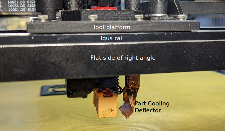
Yeah, as @o_lampe said, an aluminum profile would act as a truss and be much stiffer. I use a right angle under my Igus rails.
@Dizzwold said in Linear Rail X Gantry Support (MGN12):
@gtj0 What did you use for the part cooling on Black Beauty. I know from previous conversations that you used fans mounted on the back, then channelled through pipe, but what have you used to direct the airflow onto the printed item, the part covered in Kapton Tape?
It's like a modified mini heat-gun nozzle or something.That's it exactly. It channels the air right onto the part directly under the nozzle.
-
@Dizzwold said in Linear Rail X Gantry Support (MGN12):
Does anyone know of a way to calculate if my 3 Z axis motors on leadscrews with 2mm pitch, lead 4, and 2 starts can lift my bed assembly of 8kg.
Yes but it's complicated and my maths is a bit rusty so check the following calculations and don't take the answer as Gospel. It goes like this............
First we need the Velocity Ratio (VR). We can use displacement instead of velocity so VR will be the displacement of the effort (Xe) divided by the displacement of the load (Xl) in 1 revolution. The displacement of the effort is the circumference of the screw so Pi x 8 = 25.1mm. The displacement of the load is the lead of the screw so 4mm. So VR = 25.1 / 4 = 6.275 .
Next we need the efficiency of the screw which is given by tan (alpha) / tan(alpha + beta). Alpha is the angle of the slope of the thread which is tan^-1 (lead / Pi x D) and if my very rusty maths serves me right, that comes out at 6.231 degrees. Beta is the friction angle. I don't know what the coefficient of friction of your screws are but 0.3 is a reasonable value to use. So we can say beta is tan^-1 (0.3) = 3.233 degrees. So efficiency is 6.231/(6.231+3.233) = 0.658 or about 65%.
From that we can work out the mechanical advantage which is VR (Velocity Ratio) x Efficiency = 6.275 x 0.658 = 4.129. The mechanical advantage is the force of the load divided by the force of the effort, so we can say that the force of the effort must be the force of the load divided by the mechanical advantage.
Now the mass of the load you say is 8Kgs, therefore the force must be 8 x 9.81 (gravity) = 78.48 Newtons.
So the force of the effort must be 78.48 / 4.129 = 19.007 Newtons.
Torque is force x distance and in this case the distance is the radius of the screw so 4mm but we must work in metres so 0.004.
So for a single motor, the torque required would be 0.076N.m or 7.6N.cm.
You can say roughly one third of that per motor if you are using 3 motors (it's not quite that straight forward but it's too late in the day to go into it.As an extra data point, my bed probably weighs similar and I drive that via three 2mm lead screws with a single Nema 17 and a continuous belt.
-
Thank you for your replies an input guys.
Blimey Ian, I think is should be Professor Deckingman from now on.
With my plans to use MGN12 linear rails for the X and Y axis on my modded X5SA pro. The rail blocks trucks on the Y axis will be holding the X gantry and idlers (CoreXY). So I'm designing up some aluminium blocks to fasten the the rail blocks.
Should I use Toolplate for this or will normal plate do?
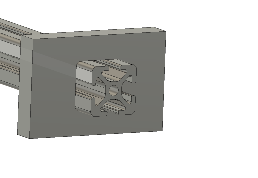
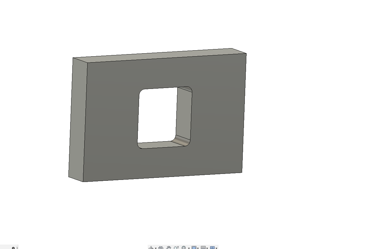
We're talking 8-10mm thick.With designing my aluminium parts for machining, if for example I wanted to machine a hole for 2020 profile to fit into to hold it square, should I add a small tolerance or just use the exact dimensions of the profile?
-
@Dizzwold Here are my Y gantry plates.
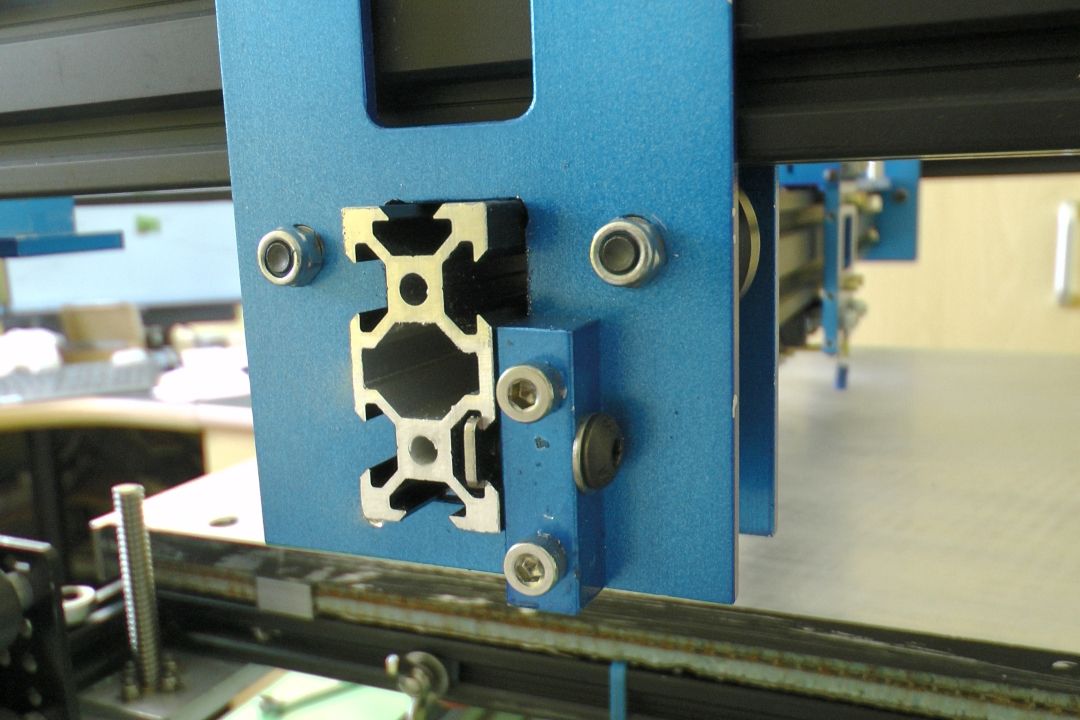
Slightly different to yours in that my X rail is 4020 rather than 2020 because its a 600mm span and carries quite a heavy "all metal" carriage and hot end assembly. When I did the maths, a single 2020 rail would have deflected too much. Also I use two plates - one either side of the Y axis rail rather than your single plate. The rectangular hole is a clearance fit for the rail - not too sloppy. As you can see, I made small blocks which bolt to the plate with one face a couple of mm or so from the edge of the rectangular cutout. Then the X rail is bolted to these blocks using a T nut and short bolt. This stops the X rail from sliding left to right but also clamps it firmly against one side of the rectangular cut-out keeping everything nice and square.
The upper rectangular cutout is just a weight saving feature.
Material is nothing special - just 3mm aluminium plate but of course I have two plates - one each side of the rail. I'd have thought something like 6mm thick stock would be plenty thick enough for your application and you don't need expensive tooling plate. Edit - I guess the material thickness should match the MGN trucks.
-
@deckingman
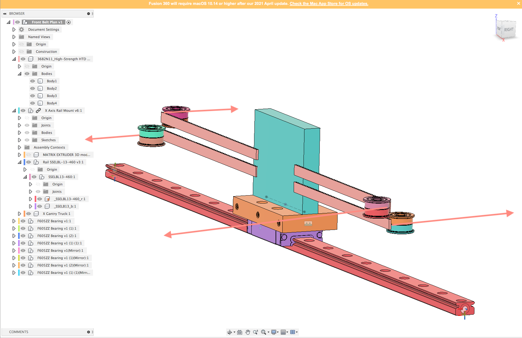
Hi Ian,Thank you, that's a novel idea with the clamping block on the side plate.
The image I show above was just a quick 'slapped together' image to demonstrate what I meant as sometimes my descriptions aren't so great.
I'm also considering a second plate bolted to this plate with a centere bolt, so the extrusion is held around it's circumference with the plate as in the above image and then basically a blind joint with the second plate, but then that's if I have enough room to do so.The problem I mostly have is I'm working with the original Tronxy X5SA Pro (330 x 300) CoreXY frame, and steeling ideas from here and there. Then I've got greedy with regards to the build plate size, going with a 400 x 400 toolplate using Ed Palisoc's/David Husolo's Triple Z with anti wobble design from the BLV Cube Project.
With this design, it also raises the build plate up with all the additional parts (compared to the Tronxy build volume).So with still being greedy and aiming to keep as much build volume as possible, without adding new printer framework I'm looking to designing a new X, Y motion system using linear rails.
This consists of the 2 Y axis linear rails going on top of the left and right of the existing frame, the X axis gantry (possibly 2020 profile), on top of the Y axis bearing trucks, then the X axis linear rail on top of the X axis profile.
This will then raise the the print head up roughly about the same amount I would loose with the new build plate/triple Z axis.
This then gives me 2 problems that I can think of so far;
1, the mounting of the idlers pulleys and belt routing as everything will now be up in the clouds
2, the possibility of ringing etc due to the weight of the printhead being above the original frame work (around 800g)Dizzwold.
-
@deckingman @gtj0 @o_lampe @mrehorstdmd
Regarding designing a coreXY belt system. When the toothed face of a belt runs around an idler pulley, should that idler also be toothed, or doesn't it make any difference?
Dizzwold.
-
@Dizzwold It depends on the pulley diameter. I once had a link to a white paper from Gates that indicated that at least 9 teeth need to be in contact with a smooth pulley. In a corexy mechanism the belts are usually bend 90 degrees around the pulleys. That means you'd need 36 teeth around the circumference of the pulley. Ignoring the fact that the teeth get closer together when you bend them around the pulley, it means you need the pulley circumference to be 72 mm (36 teeth x 2 mm pitch). That means the diameter should be 72/pi= 22.9 mm. I used 608 bearings that are 22 mm in diameter and it works fine- no artifacts from the belt teeth in the prints.
608 bearings are cheap and readily available, but they are a bit heavy and require an 8mm axle that's also heavy. You can use smaller, lighter, smooth pulleys (625s, for example) if you put twists in the belts so that the smooth back sides of the belts contact the pulleys. The machine will also be quieter at high speeds if you twist the belts. The twists can go in the belt segments that run from the drive pulleys to the corner pulleys, but you have to make sure there's clearance for the ends of the x axis as it passes by the twists.
Gates has some recommendations for twisting the belts that I don't recall exactly, but it has to do with the belt width and the length of the twisted segment. Wider belts require longer segment length for the twists. If the bed in your printer is 300 mm in Y, I believe the segments between the drive and corner pulleys will be long enough for the 180 degree twist required to use pulleys in contact with the backs of the belts, even if you use 10mm wide belts.
You can buy small, toothed pulleys that have tiny bearings, but I wouldn't expect those bearings to last very long. You're better off maintenance and reliability-wise using larger bearings as the pulleys.
Make sure you use quality drive pulleys! You can get Gates pulleys for just a few $ each from Filastruder and they really are better than the cheapos from China.
-
@mrehorstdmd
Hi Robert,
Sorry, My typo.
Hi Mark,Thank you for that. Rotating the belts seems like a very good way to go as I've been getting complaints from my neighbour.
The smaller bearing you recommend is that a typo and should be F625Z, as I can't find any 625S ?Dizzwold.
-
Hi Mark,
Sorry for the name mix-up above.
I've been reading up on your CoreXY belt configuration documents.
Referring to your Belt Segment Diagram;
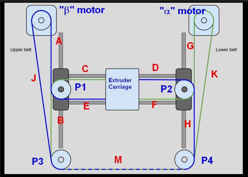
Do the belt segments C, D, E & F have to be separated, to the front and back of the X carriage, or is it possible that as long as the belts are parallel they can all be mounted in the same position, either all on the front (as demonstrated below), or all on the back of a carriage plate with using linear rails (MGN12)?
Would this work, or would there be a possibility of twisting/unwanted wear?Dizzwold.
-
@Dizzwold That's how I do mine. In my case, the belts run on the centre line of the X rail. To my way of thinking, the big advantage is that the belt tension does not impart any twisting force, even if the tension is unequal (but of course it should be equal). With the belts offset front and back, when you adjust the tension on one belt, it will twist the gantry so you have to adjust the tension on the second belt to bring it back square but that then affects the tension of the first belt etc....
For info, I documented my recent CoreXY rebuild on YouTube and created a playlist which you can reach here https://www.youtube.com/playlist?list=PLMt2DqJCk4V95a5sZzkpzvL-vM4G_JMxI
You might pick up some tips or ideas that might help................
Edit. I don't twist my belts but have never had any issues with toothed side against idlers - probably because the OpenBuilds idlers I use have quite a large circumference compare to say, a pulley.
-
I chose to stack the pulleys at the ends of the X axis, resulting in the belts being separated on the extruder carriage. If you prefer to keep the belts in the same plane on the extruder carriage, you can separate the pulleys as @deckingman has done. You can also used stacked pulleys at the corners as I have done, or separate them. I found it easiest to build the machine using stacked pulleys everywhere, so that's what I did. It did make the extruder carriage design a little more complicated, and probably not suitable for rapid or automatic tool changing.
When the belt teeth contact the smooth pulleys at high speeds they make a zipping noise at each pulley. It is quieter to twist the belts at the J and K segments so the smooth back sides of the belts contact the smooth pulley surfaces.
I meant F625 bearings (the "s" was to indicate plurality). I used F625 pulleys in my sand table that runs at 1000 mm/sec along the edges of the drawings and it has been running reliably for >2 years with drawing files that often move the magnet a few km before a drawing is done. F625 bearings are commonly used in motors (NEMA-17 steppers, for example), so they are readily available and cheap and come in a variety of grades. I used "motor grade" bearings in the sand table.
-
Hi Guys,
When using 2 flange bearings to double as an idler (SF605ZZ in my case), would you put a shim between them?
Also my X gantry is looking like it'll be 530mm. would a 2020 profile this length be strong enough to carry 800g?
Dizzwold.
-
@Dizzwold said in Linear Rail X Gantry Support (MGN12):
Hi Guys,
When using 2 flange bearings to double as an idler (SF605ZZ in my case), would you put a shim between them?
Yes, I would - definitely. You need to ensure that each bearing is free to rotate in isolation. All open builds wheels and idlers use two bearings and there is always a shim between them.
Also my X gantry is looking like it'll be 530mm. would a 2020 profile this length be strong enough to carry 800g?
I did the calcs (which are a bit tedious) for my machine. Here is a link to a resource that'll help https://openbuilds.com/threads/how-to-calculate-v-slot
 -deflection.4881/
For my machine, the X gantry rail is 600mm between supports. I can't off hand remember the exact mass but it is similar to your 800g. For that length with that mass, the deflection using 2020 was unacceptable. Again, I can't remember the exact numbers but I would consider anything greater than 0.15mm deflection as unacceptable, 0.1 to 0.15 borderline, and below 0.1mm OK. 4020 was OK and that's what I used (the 40 being the vertical dimension so 20mm wide, 40mm tall).
-
Cheers Professor Ian,
I wasn't to sure on the shims, and with watching your new build and image above it made me wonder about the length of my proposed X Gantry (530mm and roughly 800g extruder parts), and the use of 2020 profile for this purpose.
I'll have a read of the linked thread above.Thank you for your input and advice.
The link above to different profile types and deflection is a very good find. It's a shame they don't go any further with beam types such as aluminium angle etc. But non the less very informative.
Dizzwold.
-
I may have given you bum information.
But first, if you follow the link I posted it'll take you down a rabbit hole and you need to have an account and sign in. If you get through that process, it'll take you a page where you can download a spread sheet. To save you the trouble, I've downloaded it and then re-uploaded it to my Google Drive. Here is a shareable link to that spread sheet.
It seems that you need to put an "x" in the box next to the profile, then enter the "beam" length and mass. You want to look at "Simply supported bean with concentrated load". I put in length of 0.6 (metres) and mass of 0.8 (Kgs). I haven't checked the calcs but assuming the formulas are correct, then the maximum deflection is only 0.07mm for 2020 extrusion so you'll probably be OK with that.
-
A piece of same-size (3/4") square aluminum tubing would likely be lighter and stiffer than a piece of 2020. T-slot is nice stuff to use when you don't know what you might want to attach to it in the future, but is about as rigid as a wet noodle. You know what you're attaching, and where, so you don't really need to trade t-slot convenience for rigidity.
The trick with tubing is to figure out how to bolt your linear guide to it without having to drill a lot of big tool access holes. Fortunately you have a 3D printer so it isn't a problem. What you do is print a plastic piece that will hold a bunch of nuts (M3?) to match the screw spacing for mounting the linear guide, and will fit inside the tube. Then drill holes one side of the tube that will just clear the screws. Now slide the plastic piece into the tube and align the nuts with the holes and mount the linear guide, then slide the plastic tool back out of the tube.
-
@mrehorstdmd Ivan Miranda @Ivan-Miranda does a great job of making things out of square tube! eg https://www.youtube.com/watch?v=qnOci3cJapQ
He tends to drill and tap the tube, but I guess that's because he's using thicker walled tube.Ian
-
Hi Ian,
Just to revisit this before I consider getting some items machined;

What, if any gap should I add to the hole for the extrusion to fit. I'll be using something along the lines of your solution of adding a T nut perpendicular to the extrusion, but should the hole be machined exactly to the dimensions of the extrusion?Hi Mark,
The paper you mentioned on the Gates Timing belts, was it the following I've found;
https://drive.google.com/file/d/1POritr7FPCOrrN1QoxM0UfkxK0Y2iGMk/view?pli=1