IDEX BOTH ON CORE XY
-
Is it possible to currently set up IDEX as both heads driven CORE XY?
So 4 motors driving the CORE XY at all times but one head would stay outside the print area until commanded.
This seems doable just, I just don't know if the kinematics in the firm ware can handle the logic of the head that is not in use and still work in conjunction to move the gantry.My background 30 years designer spatialized equipment.
Mechanical Engineer DesignerChris T Grosbeck
MiMe.Global -
@cgrosbeck a pure CoreXY setup for IDEX involves a lot of belts and pulleys, and you need to stack belts in three to four layers instead of the normal two.
It's simpler and easier to go for Dual Markforged / Hybrid CoreXY where the Y axis is driven by two motors linearly, and both carriages are driven with a Core-style indirect motor drive.
This approach solves several problems: First of all, you get double the motor power for the heavy X gantry. Second, you get shorter belts for Y which are easier to tune since they are a simple loop. Third, you save on belt stacks. Fourth you save on pulleys. You still have three belt layers, but the Y layer is separate from the XU layers.
-
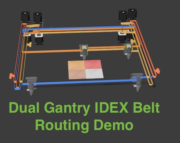
@cgrosbeck What @oliof says about belts might well be true, but my next printer is likely to be a dual-gantry like the DuellingZero.
My plan is to stretch it along the y-axis to give a printing area of about 150 by 300mm. The short x-axis will allow it to be light and to use some nice THK rails that I acquired second hand a couple of years ago. I find my Duet-powered Voron 0 to be a very nice printer for my purposes, so a larger bed is not important to me.
-
@oliof Four layers of belts is fine as this will also use four motors the cost is in consideration as commercial design for 600mm sq and up, This is not being designed cost for the home hobbyist, The team also is asking for filament change and purge on the fly with each head. So this is a large machine and the concern of stacking belts is not a problem, I am not software / firmware savvy so need help on the software / firmware side, So can this be done in the current firmware with a proper config.
Chris T Grosbeck
Sorry if I sound rude about home hobbyist but that market is out of China and we are not looking to compete at that level!
we are targeting $10000 base printer to 30000 with IDEX and dual on the fly material changing 4 or 8 per head! -
@cgrosbeck I was not arguing about cost, but complexity. A commercial machine should reduce complexity and part count to avoid maintenance load and reduce per-unit cost.
-
@cgrosbeck Yes, the firmware supports CoreXY IDEX, and has for a long time, so not "doable just"! And yes, it can handle the logic, the computations are not very difficult, see the diagrams below.
Machine kinematics are set by M669; see https://docs.duet3d.com/en/User_manual/Reference/Gcodes#m669-set-kinematics-type-and-kinematics-parameters
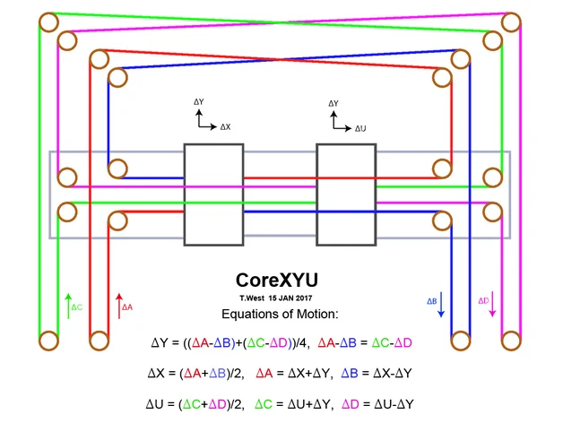
There are presets for the common machine types. I think what you are describing is actually what we refer to as a CoreXYU. A CoreXYUV would have two completely independent CoreXY gantries, including the X carriage (like @MJLew suggests). M669 already has support, and a preset, for CoreXYU and CoreXYUV. M669 allows setting up of custom kinematics, too. User @deckingman built a machine that had three separate CoreXY gantries, dubbed a CoreXYUVAB.There are two ways of doing a CoreXYU (or CoreXY IDEX); the first is as you describe, with 4 motors for the X, Y and U motion:
The second is a CoreXY with a Markforged U axis, and uses three motors, and less belt and other hardware:
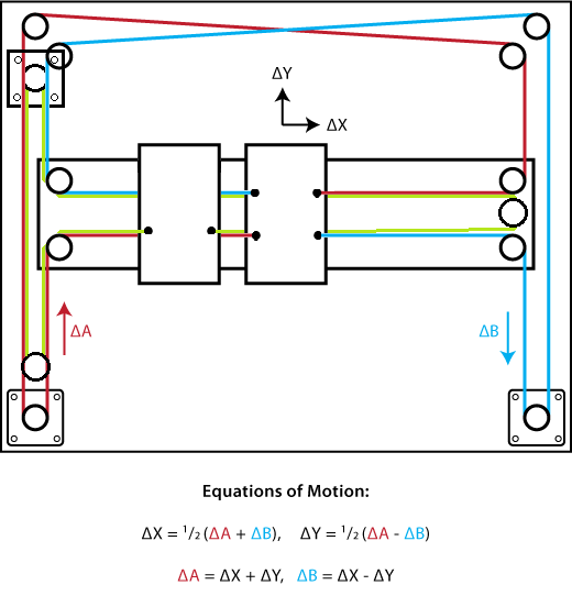
Both are supported by RRF, using the
M669 K5CoreXYU kinematic. There isn't any great advantage using the first over the second, while the first adds to the complexity.M669 also supports the dual Markforged kinematic @oliof suggests. I believe @RogerPodacter has built one of these, see https://forum.duet3d.com/post/303241
(From this thread: https://forum.duet3d.com/topic/21021/dual-markforged-kinematics)Ian
-
@oliof Appreciate that this is a fairly old topic - and sorry for the long post - just wanted to get a few ideas down together.
I have been investigating some options for a multi headed / multi colour printer for printing large multi coloured models.
I think the RatRig VCore 4 / With Hybrid Motors and IDEX 'Dual Markforge' is something like what you were describing in your post back in May.
What I am thinking along the lines of is something like a RatRig VCore4 IDEX RMMU, with a 2nd IDEX Gantry, which also has the ability for limited Z movement too.
I think it is going to need to be powered by Duet/Reprap firmware though - rather than RatOS/Klipper
My ultimate target is a machine/set of machines with the following capabilities:
- Large build area - at least 300X x 500Y x 250Z - With at least two independent gantries for parallel printing of large objects - probably using the Reprap 3.5 Multi Motion System parallel printing capability
- Each gantry being IDEX - to allow for fast colour changes for most commonly used colours, and for some models - mirror mode or duplicate mode parallel printing within the IDEX gantry.
- Filament Multiplexing - probably using something like the Reprap RMMU or BambuLab AMS - as I need up to around 12 colours in total per object.
- Parallel background colour feeding and purging etc. - which is hopefully supported by RepRep 3.5 (but not by Klipper/RatOS I believe). - See part 2 video for more details of this.
- For the multiplexed colour changes - The ability for very efficient 'flush-into object' printing to be done - with the flush-into objects potentially being printed at a different Z heights to the main object.
- Ideally in cases where fairly simple small prints are already in progress on only one of the gantries - the ability to separately start a simple 2nd print on the spare gantry.
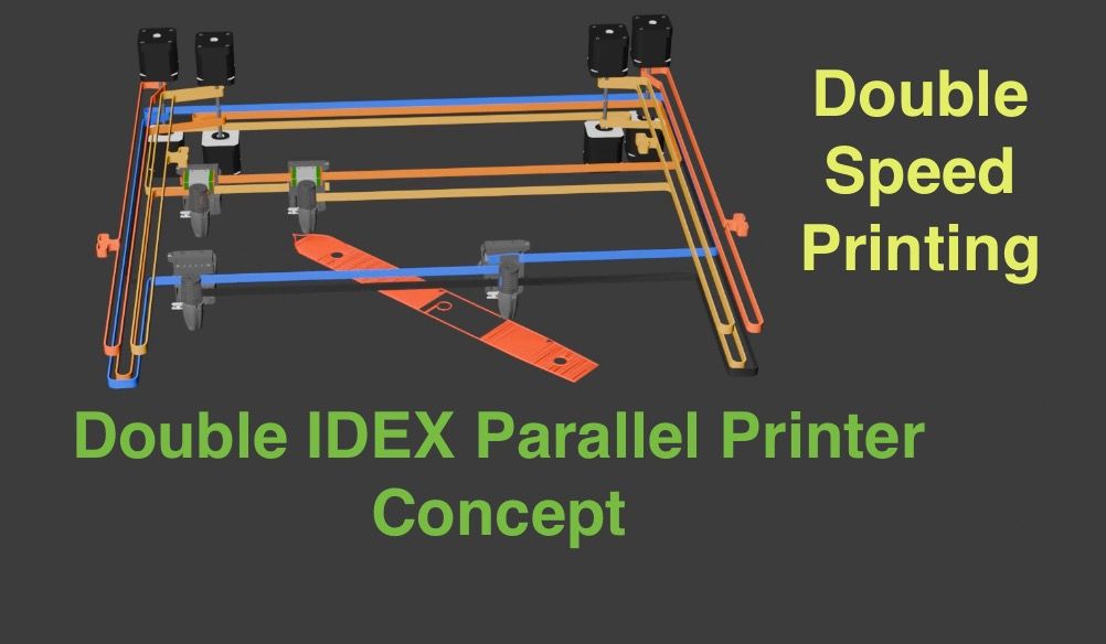
I have created a few videos demonstrating a few ideas - the most relevant to my current thoughts is Part3 of this IDEX series.
IDEX Part 3 - Dual IDEX'IDEX Part 6 - Motors and Belts'
Youtube linkWhat I would like to do next is add the ability for the 2nd Gantry to have a small amount of Z axis movement ability - so that it can be completely independent of the first gantry. I will probably add a few of the Reprap 3.5 Multi Motion System Gcode commands to my Blender add-on to drive the fully independent simulations.
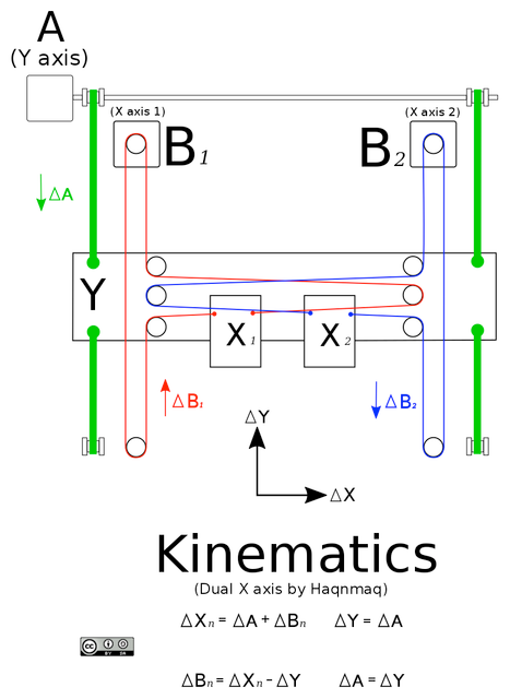
Will probably also add some animations along the lines of the diagrams posted by @droftarts in this thread to the simulations too.
The next problem is then splitting up models into sections for Multi Motion printing.
I have done some reading of this forum of posts about Multi Motion printing - mainly by @dc42 and can't find a lot of details of any slicer developments.
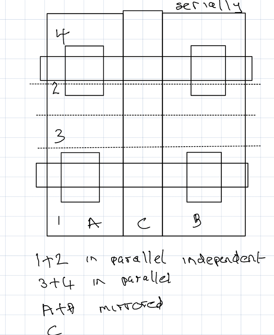
So unless work is already underway in this area I am thinking about creating a GCODE post processor that does a basic split of single head multi colour prints (probably sliced for a BambuLab X1C) into up to 3 or 4 separate areas per layer if they are big enough be warrant parallel printing on the two gantries at the same time. The reason for the 4 areas is to avoid head clashes - see this diagram.
Plus probably a 2nd post processor that does some more automated mirror mode splitting - I am currently do this in my simulations by pre-splitting up the mirrored / duplicated and single threaded parts prior to slicing into different 'virtual colours' - am then using the tool change commands generated by the slicer to switch the 'virtual' printer between IDEX modes.
-
-
@dwuk Made some good progress today on a basic gcode post processor to segment prints into the 4 sections that are going to be required for parallel printing.
The challenges were
a) Extruded Lines going out or coming in to segment
b) Extruded Lines passing both in and out of the segment
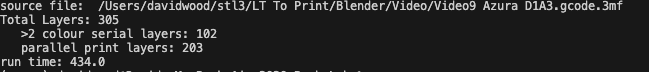
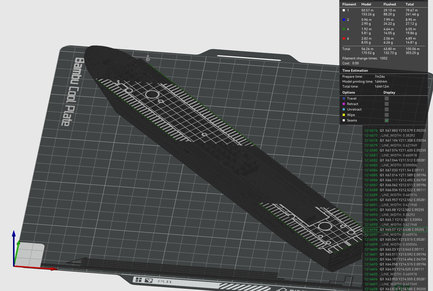
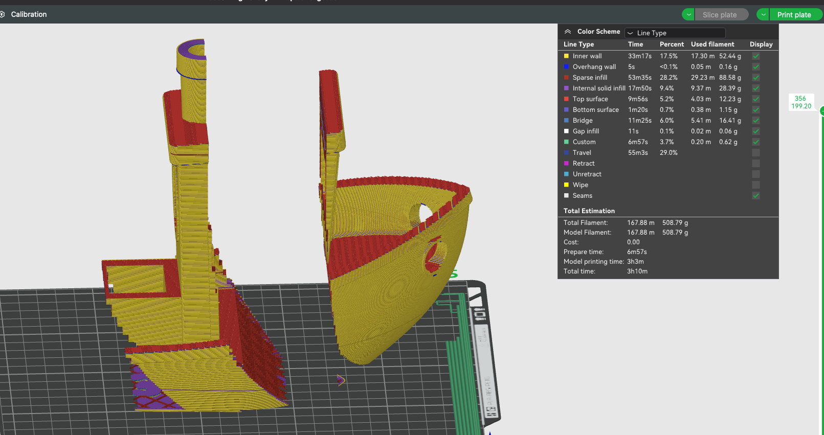
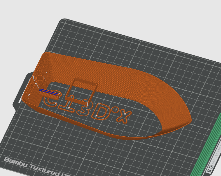
c). G2/G3 ArcsTook sliced gcode file of this
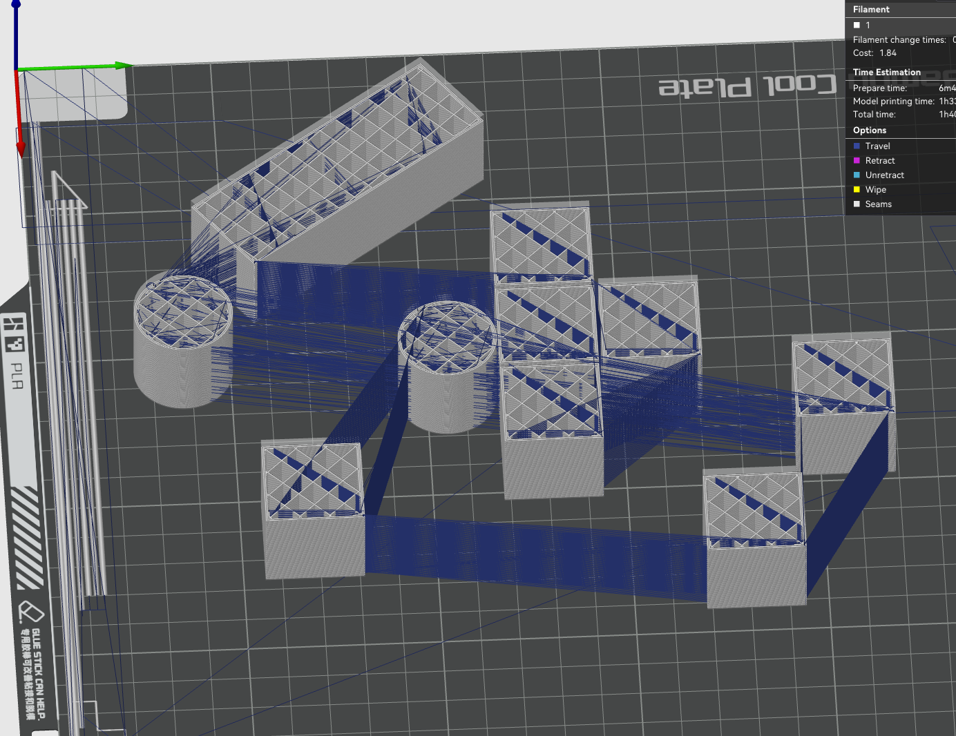
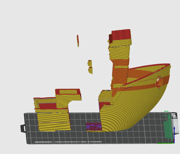
And sliced out just one section
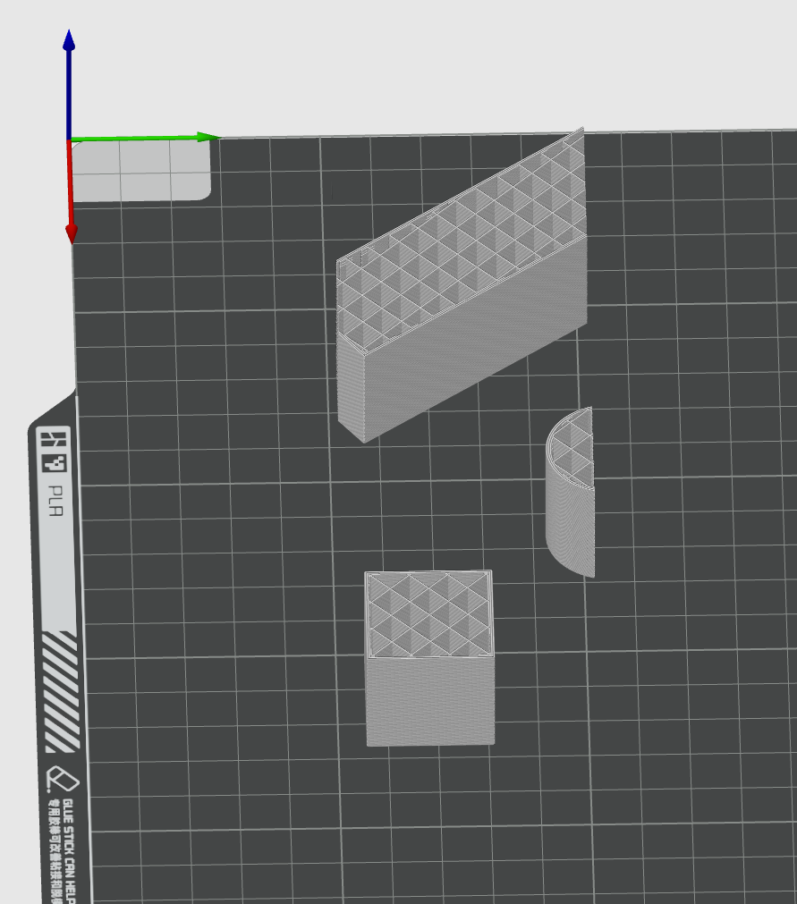
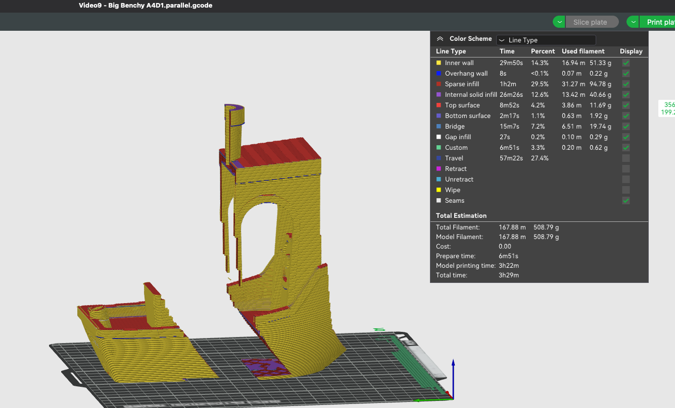
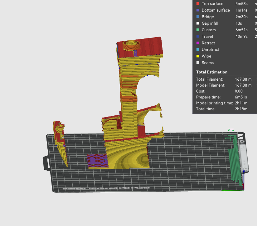
Another example for a more complex model
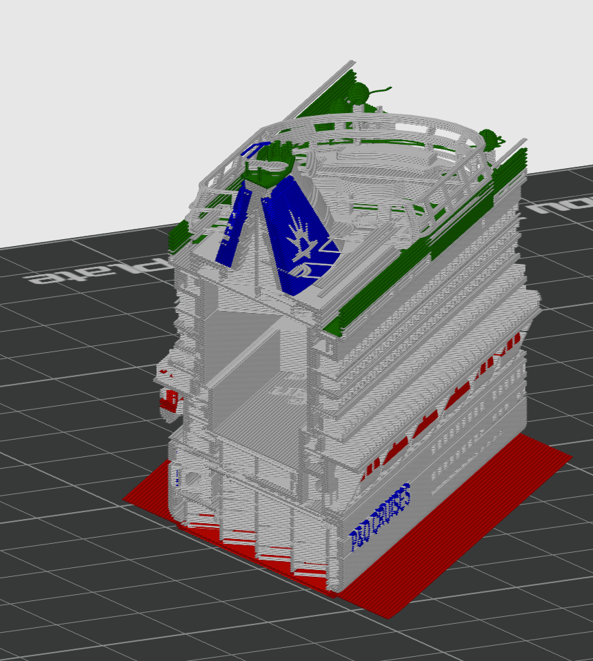
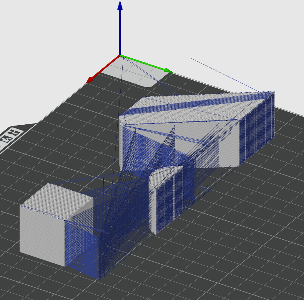
Remaining challenges before moving on to slicing the whole 4 sections and reording the gcode within each layer to do 2 of each of the sections in parallel on the front and rear gantry extruders.
Performance is fairly slow due to the low tech approach I have taken to arcs - which is to segment them into tiny line sections and treat them the same as lines - as the maths for splitting circles into up to 4 smaller sections where they intersect the border of each section got too difficult.
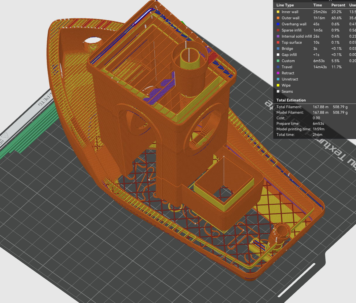
Another issue is travel moves around the cut off borders - the issue is fairly clear in this screenshot. - This will be a particular issue when printing sections that ajoin a layer on a section that has already been printed.
Will be interest to see how these segmented files actually print - should be able to run some real tests on a single extruder printer.
The approach I now think I will take with the final output is as follows:
-
Go through the Gcode file expanding out G2/G3 to G1s.
-
Go through the expanded file 4 times - creating versions of each of the 4 segments - and collecting statistics per layer per segment.
NB/ Segment precise bounds can vary a bit per layer for strength and in later versions to better spread the load - they just need to be wide enough to avoid gantry clashes. -
Final iteration - with output gcode file is generated - which will consist of GCODE, separated by laters - with each layer being either:
a). The gcode of the whole layer unsegmented - for layers with more than 2 colours per segment or not enough time needed in each segment to warrant parallel printing.
b) Segmented - with the following structure:
M596 P01
--Seg3 gcode
M596 P00
--Seg1 gcode - which can be printed in parallel to seg3
M598 - to wait for Seg3 and Seg1 to complete
M596 P01
--Seg4 gcode
M596 P00
--Seg2 gcode for printing in parallel to seg4
M598 - to wait for Seg4 and Seg2 to complete -
-
Layer segmentation working pretty well.
I set things up so layers are segmented into 4 - other than the top and bottom layers, plus every 4th layer.
Results look pretty good in Bambu Studio Preview - with segmented parts joining back together ok.
Before Join
After segments joined - inner wall only illustrated
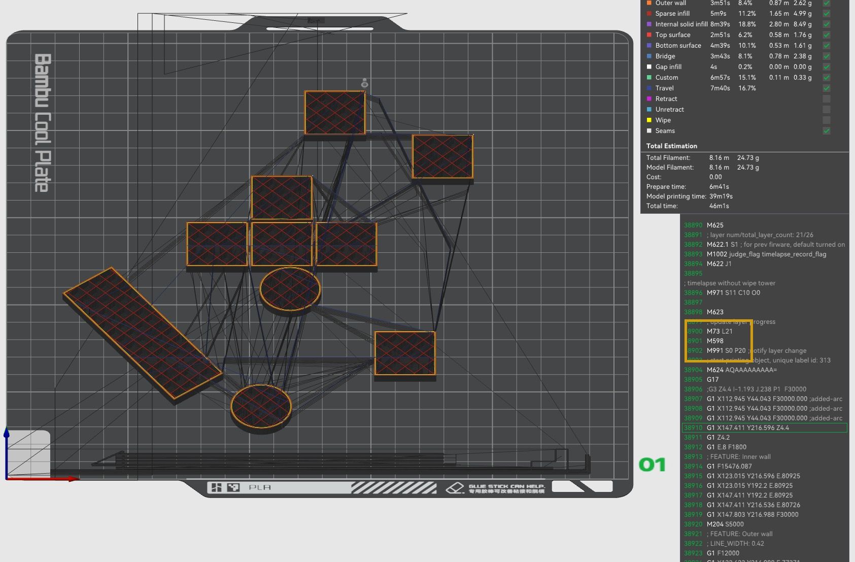
Showing the Gcode now for 4 segments
First segment - for motion system queue1
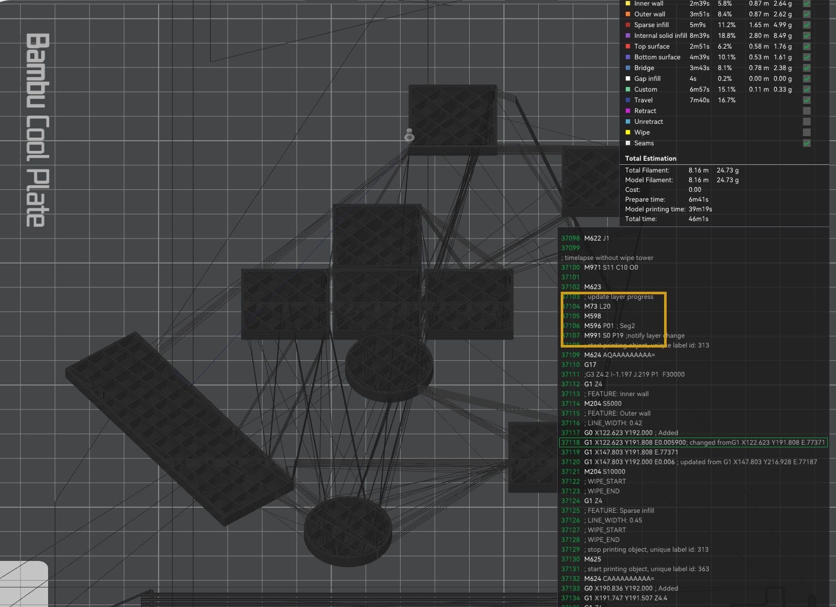
Bambu Studio showing that segment completed - by the time it gets to the gcode for queue0
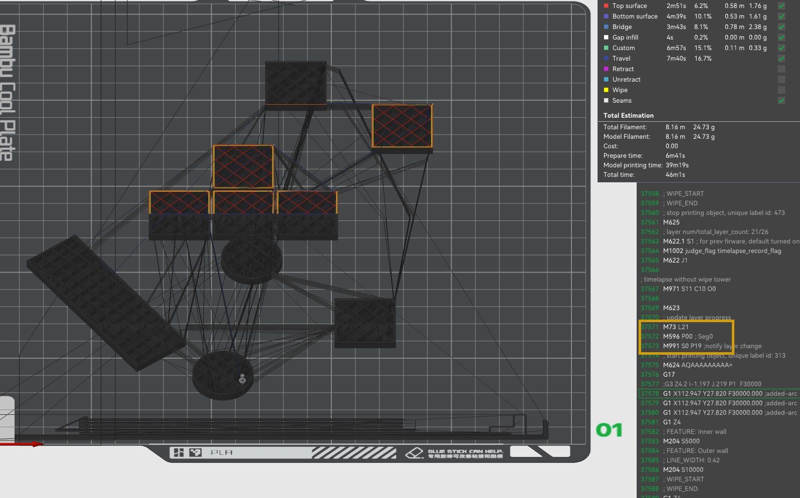
Gcode now showing wait - for both queue1 and 0 to complete, and then on to 2nd segment for queue 1
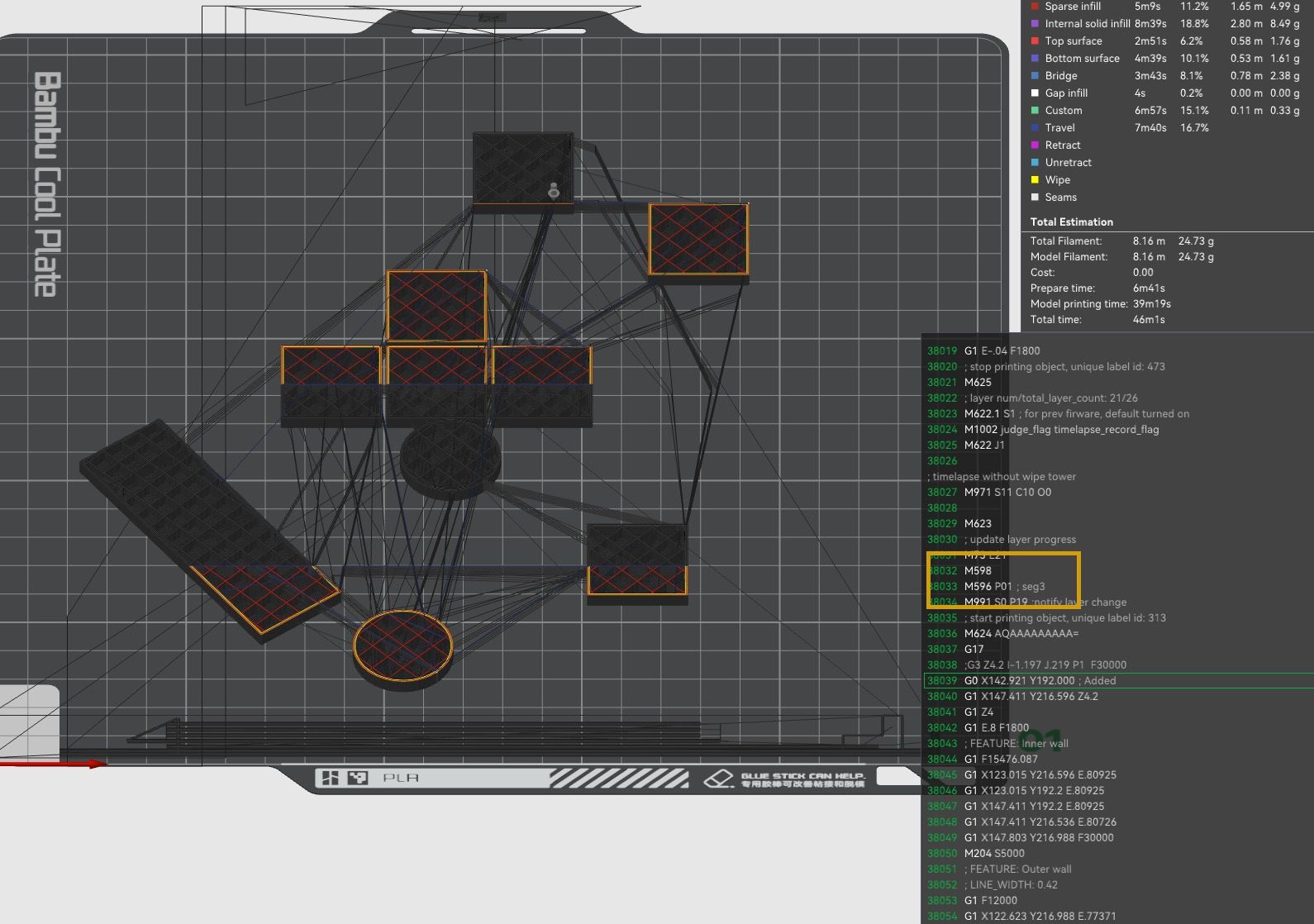
End of both queues - and then moving on to a full non parallel layer
-
@dwuk Splitting the gcode file?

I never thought of this as an option when I built the hashPrinter in 2021.
In my mind it was always the slicer who had to split the object, but that approach had it's own issues.Your approach looks very promising, although I see lots of retracts/unretracts where the tracks were chopped apart. That can end up ugly, like tons of blobs everywhere.
And of course you'll run into tool collision situations and waiting for the other tool to finish the current layer while the waiting nozzle drools dry. (just as I did)
My idea to the latter problem was, to synchronize both tool speeds, so they finish work at the same time.
Maybe you want to add that in your splitting post processor?BTW, my hashPrinter only required 4 steppers for the whole motion system ( plus 3 for Z and 4 for extruders) and all the belts where short and straight. Not such idle roller nightmare...
But lets not start a pi$$ing contest. There are pros & cons in both designs -
@o_lampe Hashprinter looks very interesting - will definitely looking for ideas on how to reduce complexity. The initial design is just Ratrig VCore4 IDEX kinematics (which is probably the printer I will be using) doubled up.
But I would like to take the design up to 4 Gantries/8 Print heads if possible - so way to reduce the number of motors in particular would be useful.
I agree that Retractions and moves around the boundaries of my segment cuts will likely be a problem - will enhance the code to allow the boundaries to be a bit more 'fuzzy' so that less line cuts will be required. Might also split out the outer wall lines and print them single threaded rather than segmented - to at least hide some of the mess inside.
Head collisions won't be a problem with this basic segmented approach - because the segments will be sized to be big enough and far enough away from each other when printing in parallel to make it impossible for the heads to ever meet.
I agree though that ideally it would be most efficient for the slicer to create the parallel printing GCODE.
You are right though about the parallel segments not finishing at the same time. In the initial version I have set every segment to be the same size (1/4 of the Y axis). It looks quite interesting in the animation seeing one segment finish before the other and the heads park.
Firstly I will try varying the sizes of the segments for every layer to a) fit in with the bounds of the print on that layer, and b) if possible within the print head clash avoidance constraints size them so that there is a similar amount of work needed by each gantry for each parallel pair - so that they finish at more or less the same time. I could also as you suggest slightly slow down the gantry with the least work so that it finishes at the same time as the other one.
Once I am fairly happy with the design I will try doing some actual printing of the segmented gcode on a single threaded printer to see how messy the edges/joins come out..
Also need to try and speed up the code - because for this example test print you will see it took quite a long while to do the segmentation - about 5 mins.
I think I will also improve the way it handles colour changes - so that it can still do some parallel printing on layers with 3 colours for example - but I was still pretty pleased that it selected 2/3rds of the layers in the example print for parallel printing.

-
@dwuk Some Basic Info and some animations of what the parallel printing might look like
-
@dwuk I'm not sure if I understood.
- You want to split a single object into separate sections
- you'll print them simultaneously on the same bed
- ...but your collision avoidance strategy is to spread the parts further apart?
If that's the case, why don't you build (4) individual printers and each one prints a section of the object?
You'll have to puzzle the sections together anyway, but that way it'll be way easier to setup mesh bed and all.
Plus, you don't need a huuuge bed, just to keep the toolheads clear -
@o_lampe Sorry if my explanation is not that clear.
The way my very basic head avoidance strategy works is that for a 2 gantry printer - lets say the total depth of the extruder Mechanism in the Y direction is 70mm (I know the Ratrig VCore4 is more than this - so might have to either modify the design or turn one of the gantries around 180 degrees).
Then in order to avoid head clashes each gantry must always be 70mm apart.
So I divide the print into 4 adjoining sections in the Y direction..
1, 3, 2 & 4.Both 3 & 2 must be at least 70mm deep.
First pass print 1 on Gantry F. and 2 on Gantry R.
Second pass print 3 on GantryF and 4 on Gantry R.As 1 and 2 are always 70mm apart then there will never be a head clash. Plus the same applies for 3 and 4.
NB/. This is just a fairly simple strategy to demonstrate the concept - ultimately the slicer or a post processor could work more intelligently and split each layer into more logical chunks that avoid splitting lines as much as possible - and then order the printing of them to avoid head clashes.
I agree that this strategy will only work on a printer with plenty of space in the Y direction and only for models that are fairly long in the Y direction. I am thinking I would like 400 to 600mm in the Y direction.
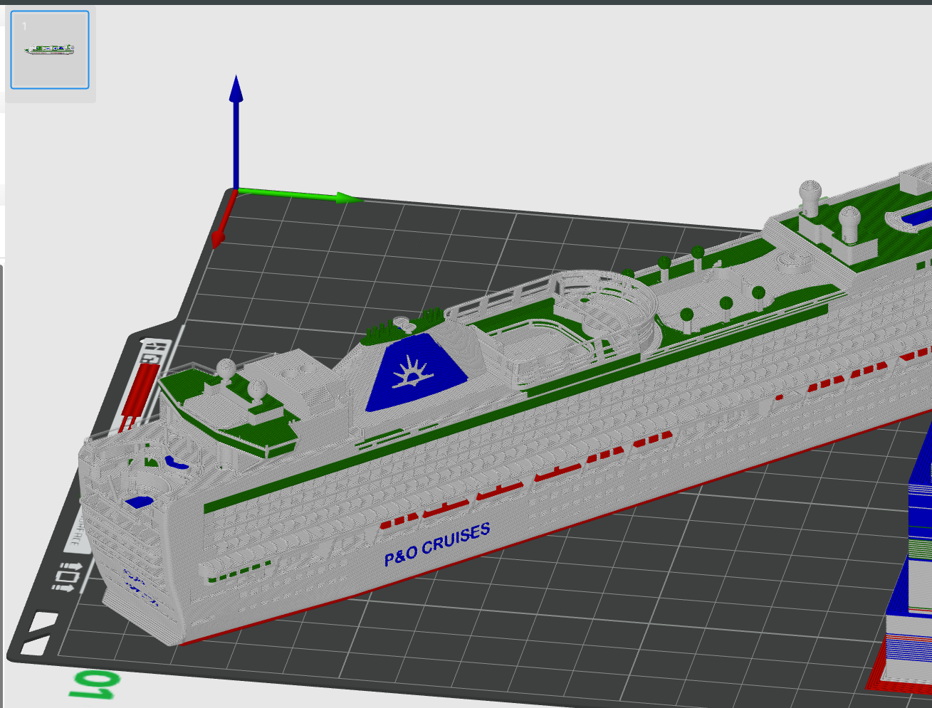
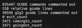
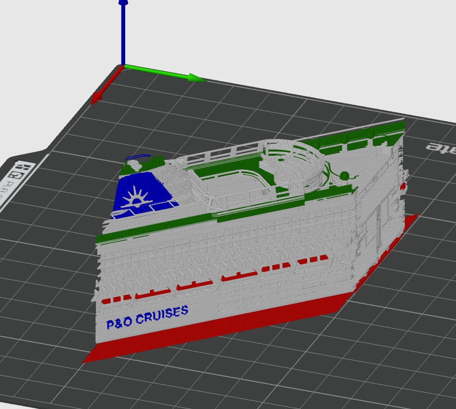
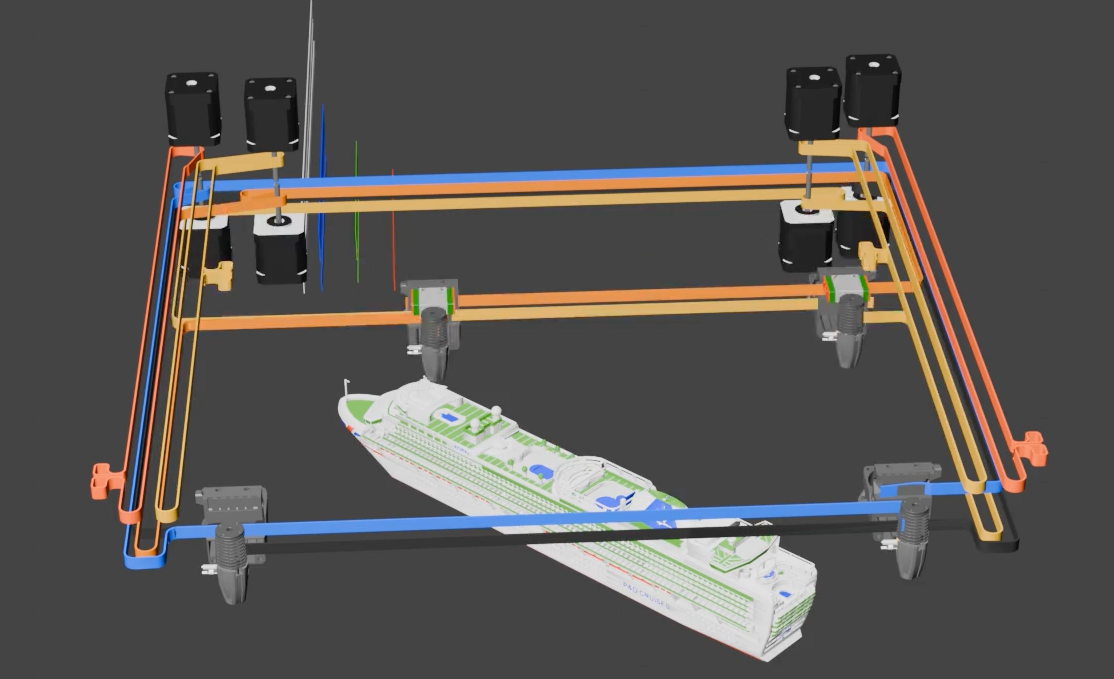
Printing on multiple printers and joining the parts together post print is also another way of doing parallel printing - if you look on Makerworld at my 1:500 Ventura or Iona Cruise ship models - you will see that I have split them into many parts that can be printed in parallel.
The downsides of this approach though are:
a) Lots of extra filament and printing time due to the parts needing to have walls/top surfaces
b) Gaps in the print where the joins are - particularly where the joints are vertical - as due to the circular shape of the nozzles it is pretty much impossible to get right angled corners that butt up cleanly together
c) For multi colour single extruder prints lots of extra waste - due to having to change colours for every part. If you look on Makerworld at my Arcadia 1:500 model - you will see that I split it into 3 parts - but they are all on the same plate to avoid flush waste - at the cost of not being able to parallel print it. -
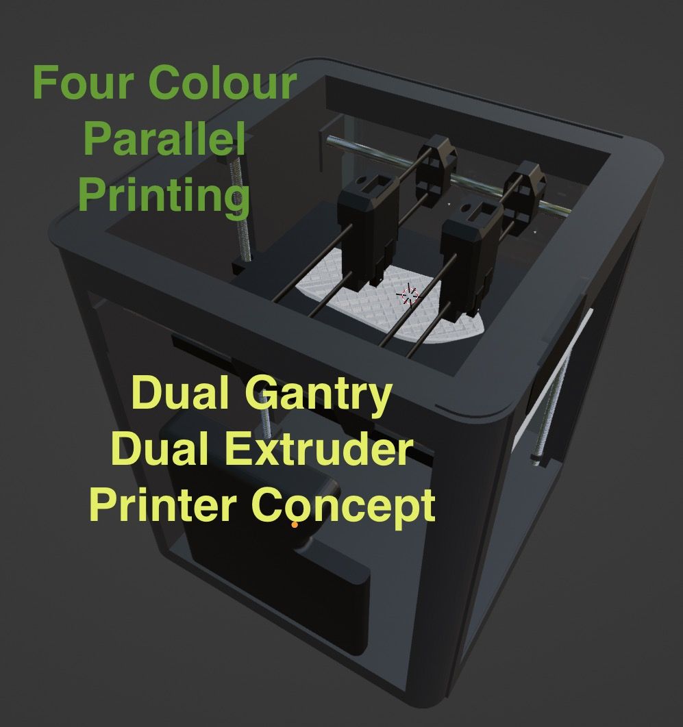
A slightly better quality video with head parking improved - picturing a Dual Extruder rather than IDEX variation - but essentially the same simulations - as Video Part 9 above.
IDEX Part 7 - Dual Extruder Dual Ganty.
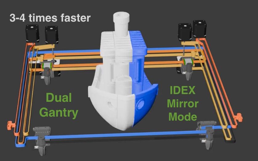
IDEX Part 10 - Dual Gantry IDEX Mirror Mode demo
-
Made further progress on the segmentation post processor:
- Made it so that all outer walls will be printed single threaded to ensure surface quality
- Changed the segment split points to change them for every layer based on the size of the layer - for more efficient parallel printing, plus also improved strength.
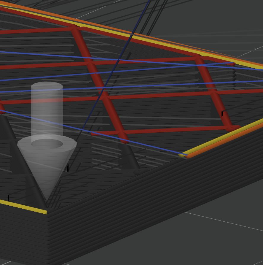
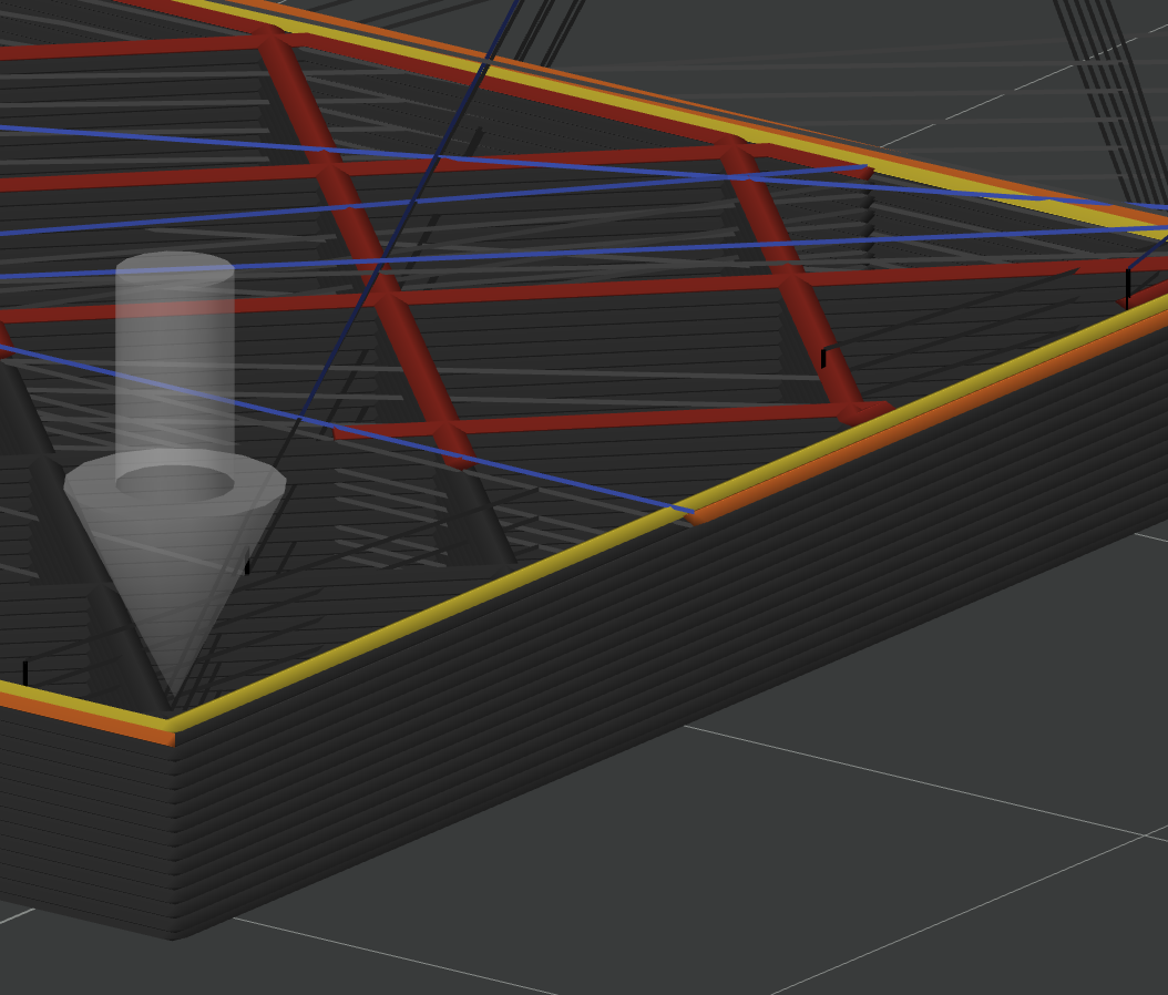
Example First set of two segments that would be parallel printed - note the gap between them to avoid head clashes. - Yellow is the inner walls.
With second set of two segments shown
Outer walls (mostly) - that will be printed single threaded to help with print quality
-
@dwuk I remember now, I've discussed the striped sections before on this forum. Was it you, who came up with it?
It was the same time I started using resin printers and immediately saw their advantages against FDM printing.
Opposite to the rounded corners you get with FDM, the resin-print edges are sharp and easy to glue together.
Unfortunately no multicolor prints, but ~10x smaller surface details possible. Plus: no problem with overhangs. -
@o_lampe Not me as only just joined the forum - but yes I agree that Resin likely to be better with corners as I presume the pixels are effectively square or combinations of them appear to be. I've done quite a lot of investigations into eliminating round corners by adding extract features that need to be shaved off - see here - but in the end for ships it doesn't really matter that much as the real ships usually have lots of visible weld joins on them.
Further improvements made today to
 outer wall isolation and layer by layer resizing of segments here
 -
As suggested by @johannesvannahme8631 on YouTube - have improved my 4 head autoswitch, Mirror and Parallel printing demo a bit.
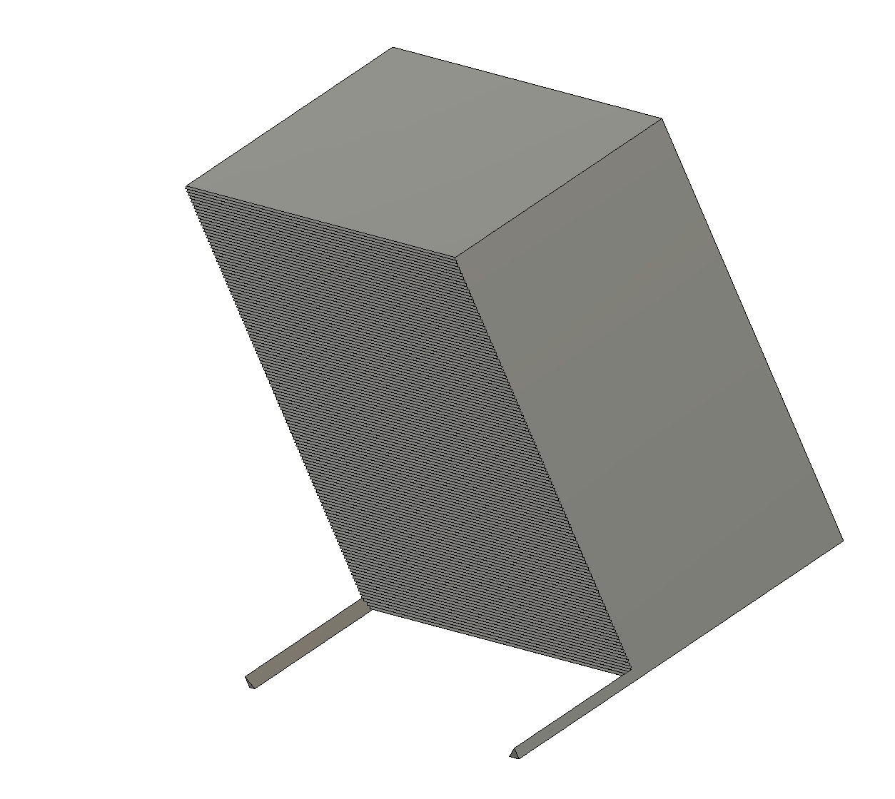
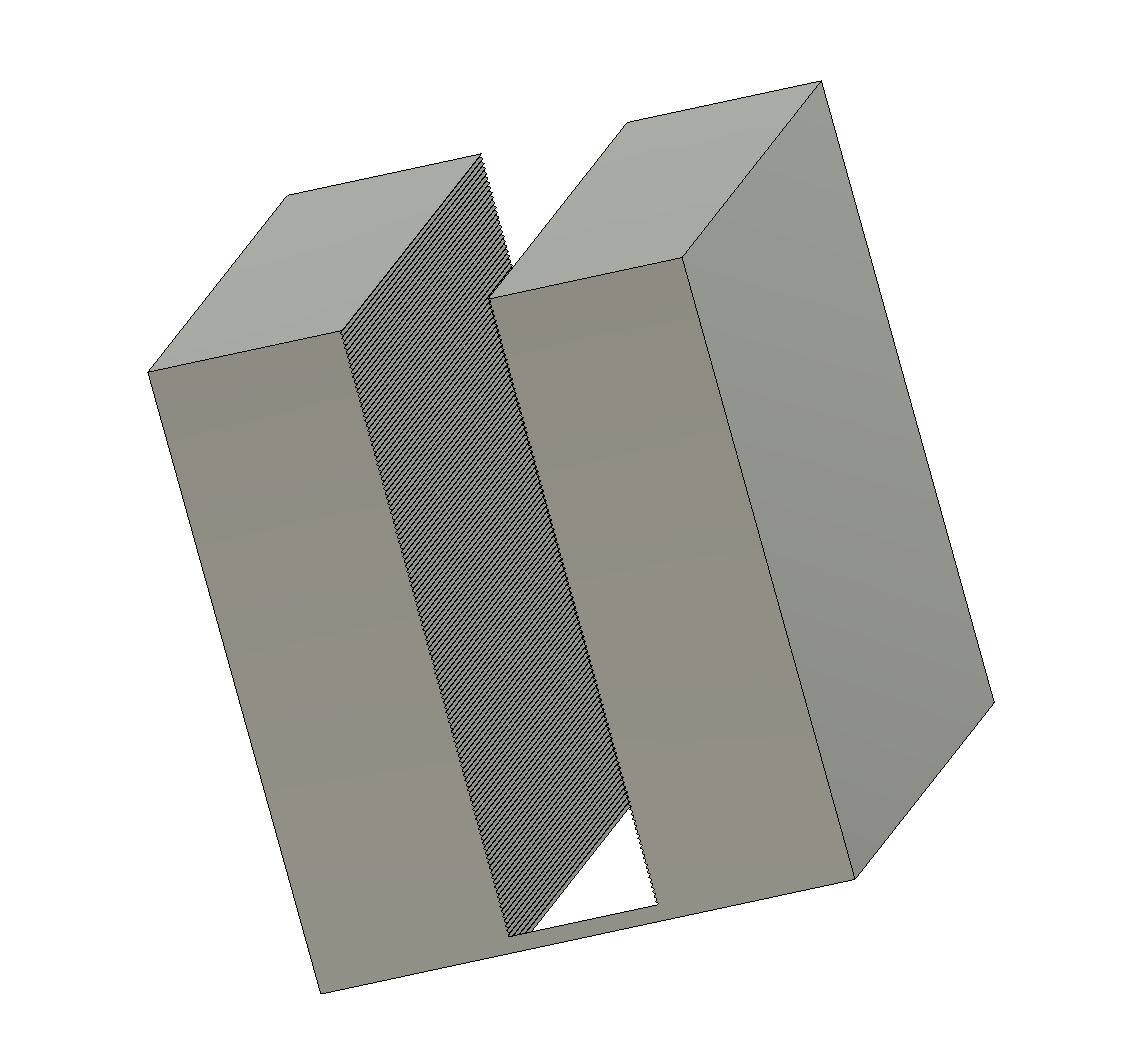
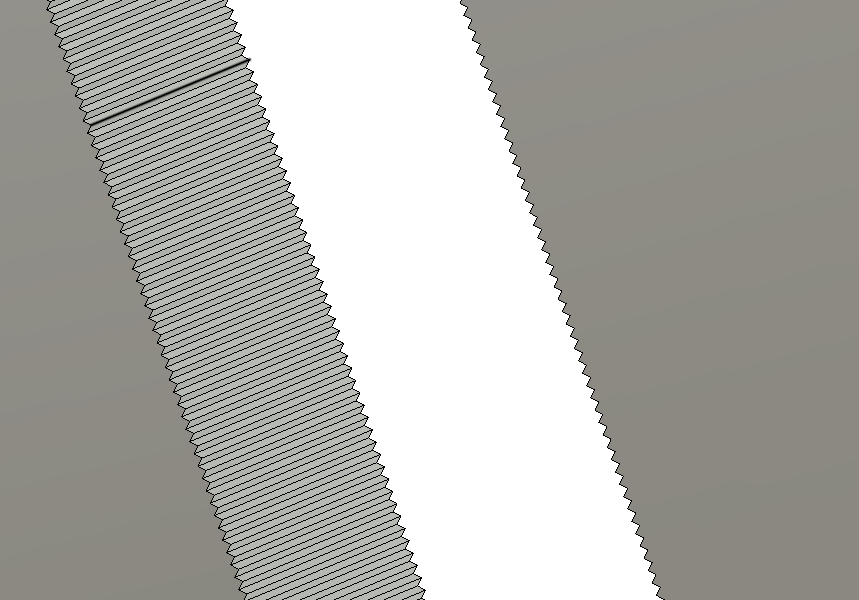
I created some cutter parts with edges that go in an out for added strength using Fusion 360 - that can be used in BambuStudio (or Orca I would imagine) as negative parts to
a). Cut out the middle - that can't be mirrored due to head clashes
b) Cut out just the left hand side to be mirrored.
I then cloned two copies of the benchy in the same place on the build plate - one for the mirrored half - in tool4, and one for the centre part in tool1.
I then applied the appropriate negative cutter part to each clone.
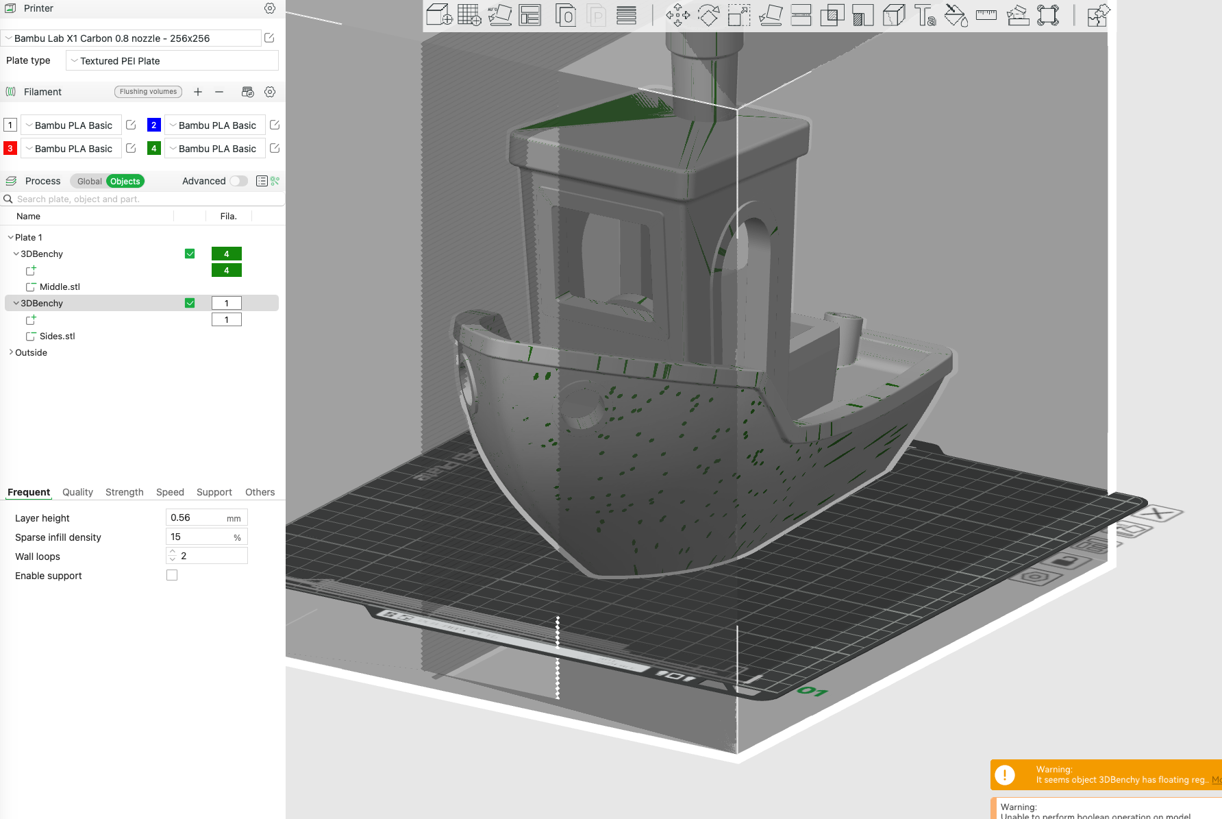
And ended up with this after slicing
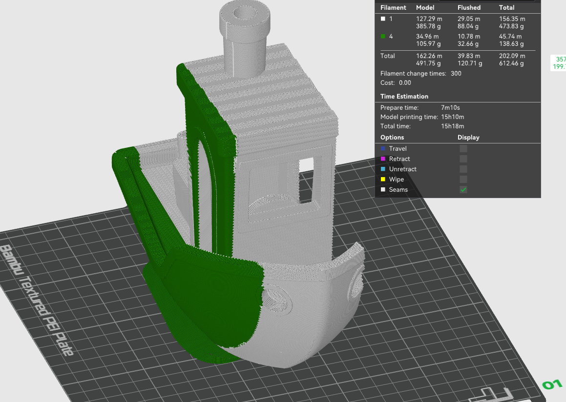
You will see from the simulated print that the join between the mirrored part and the standard printed part in the middle is now using the profile from the Fusion 360 cutter.
You still get walls between the mirrored and non mirrored part which is a bit wasteful - so I might do another GCODE post processor to do this type of segmentation too.