Duet3D Logo Duet3D
    • Tags
    • Documentation
    • Order
    • Register
    • Login

    Z tool pre-setter sensor wiring

    Scheduled Pinned Locked Moved Solved
    Duet Hardware and wiring
    6
    18
    457
    Loading More Posts
    • Oldest to Newest
    • Newest to Oldest
    • Most Votes
    Reply
    • Reply as topic
    Log in to reply
    This topic has been deleted. Only users with topic management privileges can see it.
    • RockBundefined
      RockB
      last edited by

      Hello,

      I want to use a high-precision tool setter limit switch (https://www.automationdirect.com/adc/shopping/catalog/sensors_-z-_encoders/limit_switches/plunger_actuator/p11ddb-duld) as a Z probe in a multi-tool tool changer machine. Each tool will come down and touch this sensor as part of Z calibration.

      The sensor only has two wires and was wondering what would be the best way to wire this.
      Datasheet: https://cdn.automationdirect.com/static/specs/lshighprectoolsetls.pdf

      2c7438d3-b1fd-478a-aee9-462eef31597e-image.png

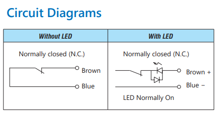
      Since there is no "signal" input to wire into the IO port on Duet3 mainboard, What would be the best way to wire and configure this 2-wire sensor as a Z probe?

      jay_s_ukundefined 1 Reply Last reply Reply Quote 0
      • jay_s_ukundefined
        jay_s_uk @RockB
        last edited by

        @RockB which one did you get? With or without the LED?

        Owns various duet boards and is the main wiki maintainer for the Teamgloomy LPC/STM32 port of RRF. Assume I'm running whatever the latest beta/stable build is

        RockBundefined 1 Reply Last reply Reply Quote 0
        • RockBundefined
          RockB @jay_s_uk
          last edited by RockB

          @jay_s_uk One with LED. Both are two wires though. There is no separate "signal" wire that can be wired to iox.in; Hence was a little confused.

          3dd05586-cbce-4177-b1a4-1404460c2b25-image.png

          RockBundefined 1 Reply Last reply Reply Quote 0
          • RockBundefined
            RockB @RockB
            last edited by

            @jay_s_uk @droftarts @dc42 any suggestions?

            There is an LED indicator on the sensor and a 10mA limit so the LED doesn't get damaged when connected to 24V. I have soldered a 2K ohm resistor to limit the current. Simple testing by directly connecting the brown wire to +24V and black to GND works fine. The sensor is NC, and pressing the plunger breaks the circuit.

            I was thinking of connecting the brown (+) to iox.in and black (-) to the GND in the IO port of Duet3 6HC and enabling pull-up resistor. Still need to connect it to 24V to power it and I am not sure how to do this with only two wires.

            jay_s_ukundefined dc42undefined 2 Replies Last reply Reply Quote 0
            • jay_s_ukundefined
              jay_s_uk @RockB
              last edited by

              @RockB ioX.in and ground would be the usual way and that would be the way to connect the without LED version. Not sure for the one you've got though

              Owns various duet boards and is the main wiki maintainer for the Teamgloomy LPC/STM32 port of RRF. Assume I'm running whatever the latest beta/stable build is

              1 Reply Last reply Reply Quote 0
              • dc42undefined
                dc42 administrators @RockB
                last edited by

                @RockB here's one option. Connect the switch plus 2K series resistor between +24V and the IO_IN pin of your selected port. Connect a resistor of about 330 ohms between the IO_IN pin and ground.

                Duet WiFi hardware designer and firmware engineer
                Please do not ask me for Duet support via PM or email, use the forum
                http://www.escher3d.com, https://miscsolutions.wordpress.com

                RockBundefined 1 Reply Last reply Reply Quote 1
                • RockBundefined
                  RockB @dc42
                  last edited by RockB

                  @dc42 Thanks for the info. I have created a circuit as below. The brown and blue wires represent the two wires from the switch/sensor.

                  cec404c2-a7fa-49e2-a501-15f5adb684f8-image.png

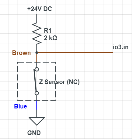
                  I have tested the voltage between io3.in and GND using a multimeter. When the Switch is not pressed, the reading is about 1.8V, and when the switch is pressed, the reading changes to 19.8V

                  I have configured a Z probe in config.g as follows:

                  ; Z Probe
                  M558 K0 P5 C"!io3.in" ; Z-probe tool setter connected to io3.in pin
                  

                  However, when the value of the Z probe in DWC doesn't seem to change. It just stays at 0. Even manually pressing the switch to trigger it does nothing, but I can see the voltages change in the multimeter
                  a0ef8684-0957-42d1-b3e5-d9887355407e-image.png

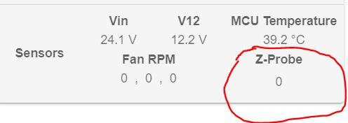
                  Any suggestions as to why the Z probe value in DWC is not changing?

                  I plan to use M585 to determine Z height during probing.

                  Phaedruxundefined 1 Reply Last reply Reply Quote 0
                  • Phaedruxundefined
                    Phaedrux Moderator @RockB
                    last edited by

                    @RockB said in Z tool pre-setter sensor wiring:

                    K0

                    since you've defined K0 you must include a K0 in all other references to the probe usage and configuration. Eg G30 K0

                    If you only have a single Z probe, just leave the K0 off entirely.

                    Z-Bot CoreXY Build | Thingiverse Profile

                    RockBundefined 1 Reply Last reply Reply Quote 0
                    • RockBundefined
                      RockB @Phaedrux
                      last edited by RockB

                      @Phaedrux Understood, but the issue seems to be the Z probe not changing value in DWC even with manual triggering. The documentation says to expect 0 when not triggered and 1000 when triggered.

                      Checking the voltages using a multi-meter, I can clearly see the change from 1.9V to 19.8V with manually pressing the Z probe/switch.

                      Any suggestions on what is going on and why the Z probe value is not changing?

                      @dc42

                      oliofundefined 1 Reply Last reply Reply Quote 0
                      • oliofundefined
                        oliof @RockB
                        last edited by

                        @RockB it's possible the probe triggers and the print head lifts fast enough after triggering that DWC doesn't update the display

                        <>RatRig V-Minion Fly Super5Pro RRF<> V-Core 3.1 IDEX k*****r <> RatRig V-Minion SKR 2 Marlin<>

                        RockBundefined 1 Reply Last reply Reply Quote 0
                        • RockBundefined
                          RockB @oliof
                          last edited by

                          @oliof Thank you for the suggestion but there is no print head movement in this test. I am pressing the switch manually and actually holding it pressed for a few seconds. Still no change in Z probe reading shown in DWC and also in Object model.

                          1 Reply Last reply Reply Quote 0
                          • Phaedruxundefined
                            Phaedrux Moderator
                            last edited by

                            Firmware and DWC version?

                            Z-Bot CoreXY Build | Thingiverse Profile

                            RockBundefined 1 Reply Last reply Reply Quote 0
                            • RockBundefined
                              RockB @Phaedrux
                              last edited by

                              @Phaedrux FW and DWC both at 3.5.2

                              droftartsundefined 1 Reply Last reply Reply Quote 0
                              • droftartsundefined
                                droftarts administrators @RockB
                                last edited by

                                @RockB io3.in expects between 0V and 3.3V to trigger it, but has a threshold somewhere between (probably around 1.5 or 1.6V) between being not triggered and triggered. If you're getting between 1.9V and 24V, io3.in will be permanently triggered. The ! in the pin definition inverts this, so it is permanently NOT triggered. Did you add the 330 ohm resistor between io3.in and GND, as @dc42 suggested? This should pull down the 1.8V to 0V.

                                Does the LED light up on the switch?

                                Ian

                                Bed-slinger - Mini5+ WiFi/1LC | RRP Fisher v1 - D2 WiFi | Polargraph - D2 WiFi | TronXY X5S - 6HC/Roto | CNC router - 6HC | Tractus3D T1250 - D2 Eth

                                RockBundefined 1 Reply Last reply Reply Quote 0
                                • RockBundefined
                                  RockB @droftarts
                                  last edited by RockB

                                  @droftarts Ian, I tried adding the 330 ohm resistor between io3.in and GND - this causes the original 19.8V to drop to 3.2 V when switch is pressed (open); however in its closed (default) condition the voltage just drops from 1.9V to 1.8V. So now I am getting voltages in the range 1.8V to 3.2V and the lower voltage is still higher than the threshold for input pin.

                                  LED does light up on the switch when powered (default state is NC) and goes off when pressed (open) as it should.

                                  Any suggestions on how to further reduce the lower voltage so that it’s below the threshold? A circuit diagram would be helpful.

                                  droftartsundefined 1 Reply Last reply Reply Quote 0
                                  • droftartsundefined
                                    droftarts administrators @RockB
                                    last edited by

                                    @RockB I think you misunderstood @dc42's suggestion. It should be 24V > Switch > 2.2k resistor > io3.in > 330 ohm resistor > GND, ie a voltage divider circuit. Something like this:

                                    a131aa7d-01fa-4857-8a66-e04f7a12db4c-image.png

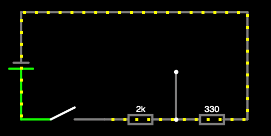
                                    The wire between the resistors connects to io3.in. Here's a circuit simulation: https://tinyurl.com/233sf6pk
                                    With the switch closed, io3.in gets 3.3V. When it's open, it's not connected, so should be 0V.

                                    Ian

                                    Bed-slinger - Mini5+ WiFi/1LC | RRP Fisher v1 - D2 WiFi | Polargraph - D2 WiFi | TronXY X5S - 6HC/Roto | CNC router - 6HC | Tractus3D T1250 - D2 Eth

                                    RockBundefined 2 Replies Last reply Reply Quote 0
                                    • RockBundefined
                                      RockB @droftarts
                                      last edited by

                                      @droftarts Ah! This makes sense. Will give this a try. Thanks

                                      1 Reply Last reply Reply Quote 0
                                      • RockBundefined
                                        RockB @droftarts
                                        last edited by

                                        @droftarts Tested this and works as expected. Just changed the 2K resistor to a 2.7K resistor to limit the overall current below 10mA. Thanks

                                        1 Reply Last reply Reply Quote 0
                                        • Phaedruxundefined Phaedrux marked this topic as a question
                                        • Phaedruxundefined Phaedrux has marked this topic as solved
                                        • First post
                                          Last post
                                        Unless otherwise noted, all forum content is licensed under CC-BY-SA