6XD I/O >> Issue solved
-
M42 P2 S1
echo state.gpOut[1].pwmM42 P2 S0.5
echo state.gpOut[1].pwmM42 P2 S0
echo state.gpOut[1].pwm -
@tecno said in 6XD I/O >> Faulty Driver 5:
echo state.gpOut[1].pwm
Wrong pin. Use:
echo state.gpOut[2].pwmIan
-
-
-
Now suddenly the OUT2 works, so go figure what is going on. Cold soldering seems far away but could be.
Been take out plugs and inserted them testing.Whole day yesterday I did not see the LED light up but OUT1 and OUT0 was working.
So DRIVER5 is still an issue here.
-
-
@tecno Can you post a good picture of both sides of the board, please. There's so very little to go wrong with these ports, I feel like it's something obvious. Did you check it with a multimeter, like I asked you to?
out2 is still working correctly? Does the LED come on when active?
Also, please send M586 and post the response, to see what network protocols are enabled, because your config doesn't have any set.
Ian
-
@droftarts
Hi Ian,
Re multimeter = no as you can see it is not so accessible in the video. Later on today.
https://photos.app.goo.gl/L56Zn79kaww26Q4U6out2 is OK
2024-09-25 09:26:27 m586
CORS disabled
HTTP is enabled on port 80
FTP is disabled
TELNET is disabled
Multicast Discovery is disabled
MQTT is disabledCheers
Bengt -
Pictures of 6XD board https://photos.app.goo.gl/6ME2iY7CesXBjeKPA
-
@tecno Were you able to do any tests with a multimeter? I can't see anything obvious from the pictures.
Ian
-
@droftarts
Pls repeate exactly what you want me to measure now that the board is in the open. -
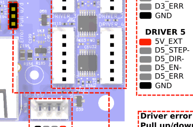
@tecno From the video I can see that you're using 3 of the pins of each driver connector: 5V_EXT, D#_STEP- and D#_DIR-. I can't clearly see Driver 5, but I assume it is the same as the others.
With the multimeter, and the Duet powered, and being careful not to touch probe to the wrong pins (especially not to touch across 5V pins to 3.3V pins):
- Test for 5V between 5V_EXT and GND on the driver 5 connector. This should read 5V.
- Test for 5V between 5V_EXT and D5_DIR-. Send a command that moves the axis one way, then the other. You should get 5V in one direction, and 0V in the other direction.
- It may be difficult to see a signal if you put the multimeter between 5V_EXT and D5_STEP-, because the step pulses happen faster than the multimeter can register them. You could try doing a fast move, which might register.
- You could also do the tests on Driver 4, so you can see what the expected response is.

Let me know how that goes.
Ian
-
Hi Ian,
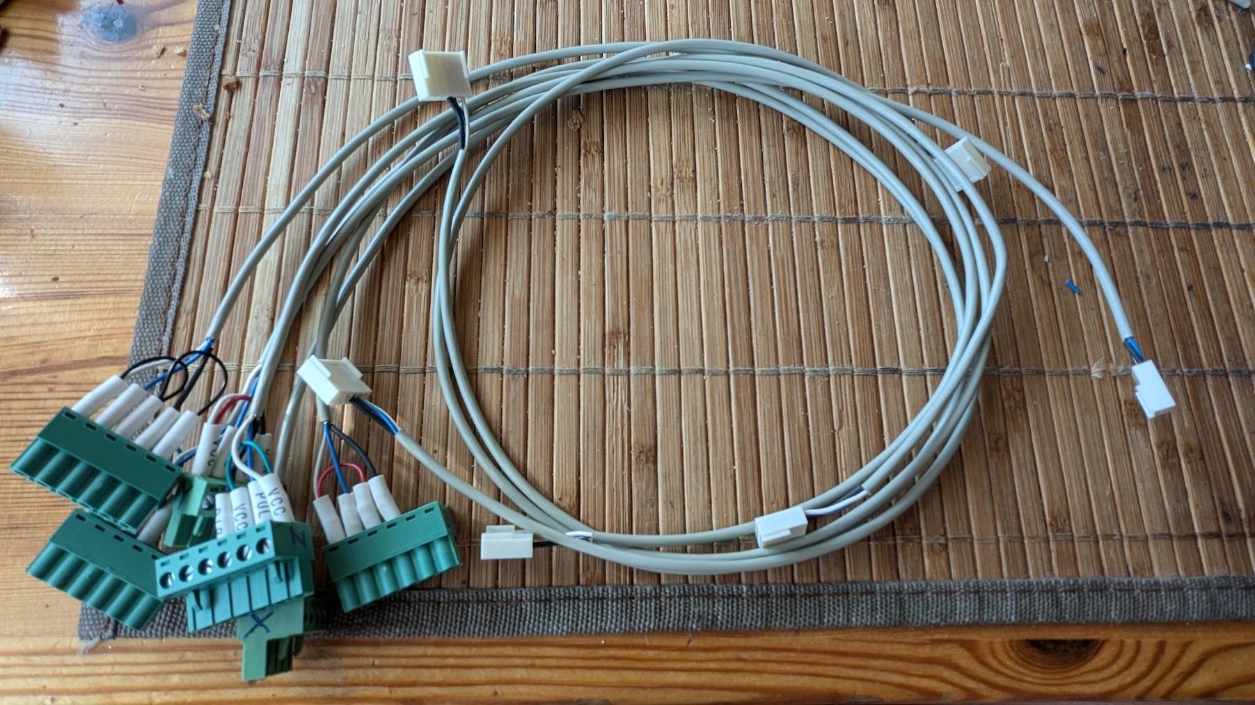
Looks like the 3 wires original cable is not to par, brittle so crimps go bad. Will make new wireing to all motors.
This el cheapo chinese cable, found also twisted wire splices with only shrink tubing loosely fitted.DMM test shows driver to be OK
I hope I have enough crimpconnectors

Cheers
BEngt -
@tecno Okay, that's good news, I guess! But more work for you. Let me know how you get on.
Ian
-
Yes a lot of extra work to make new cables. Will report!
-
New set of cables ready.

-
-
@tecno Phew! Glad it's all working. Hopefully your faith in the 6XD is restored.
Edit: You weren't tempted to wire in the enable signal as well?
Ian
-
No need for enable as I see it. 6XD is a very nice controller.
Now I have to sort out further I/O
-
@tecno you only need the Enable connections to the drivers if you want the Duet to be able to turn off the motor current. If you leave them disconnected, the motors will be energized whenever power is applied to the drivers.
