@zapta said in Filament force measurement system:
@wurstkarton said in Filament force measurement system:
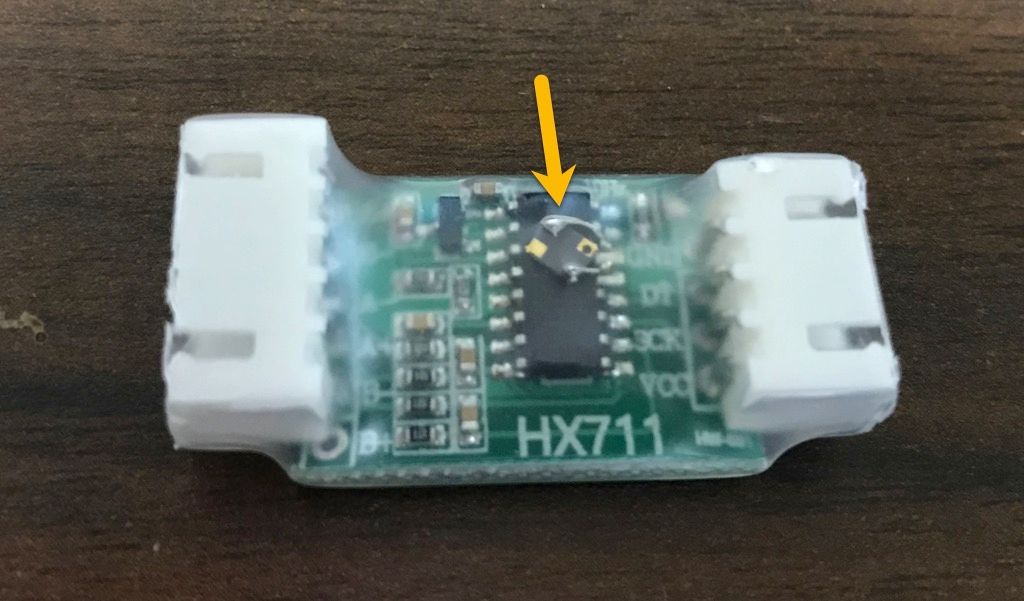
The HX711 is supplied with 5V from the Pi and takes 80 samples per second
It's not that difficult to increase the sampling rate up to 140 samples/sec by adding a crystal and changing a jumper. The data sheet has the necessary information. For example, I increased mine to 100Hz with a 13824000 HZ crystal.
Thanks for the info, but I think also 140 samples/sec are not enough. I'd guess I need 1k samples a second to make a real difference for taking a closer look at e.g. retraction.
Nothing that could not be solved with a reasonable DAC and instrumentation amplifier, but nothing that I'll do soon... ")

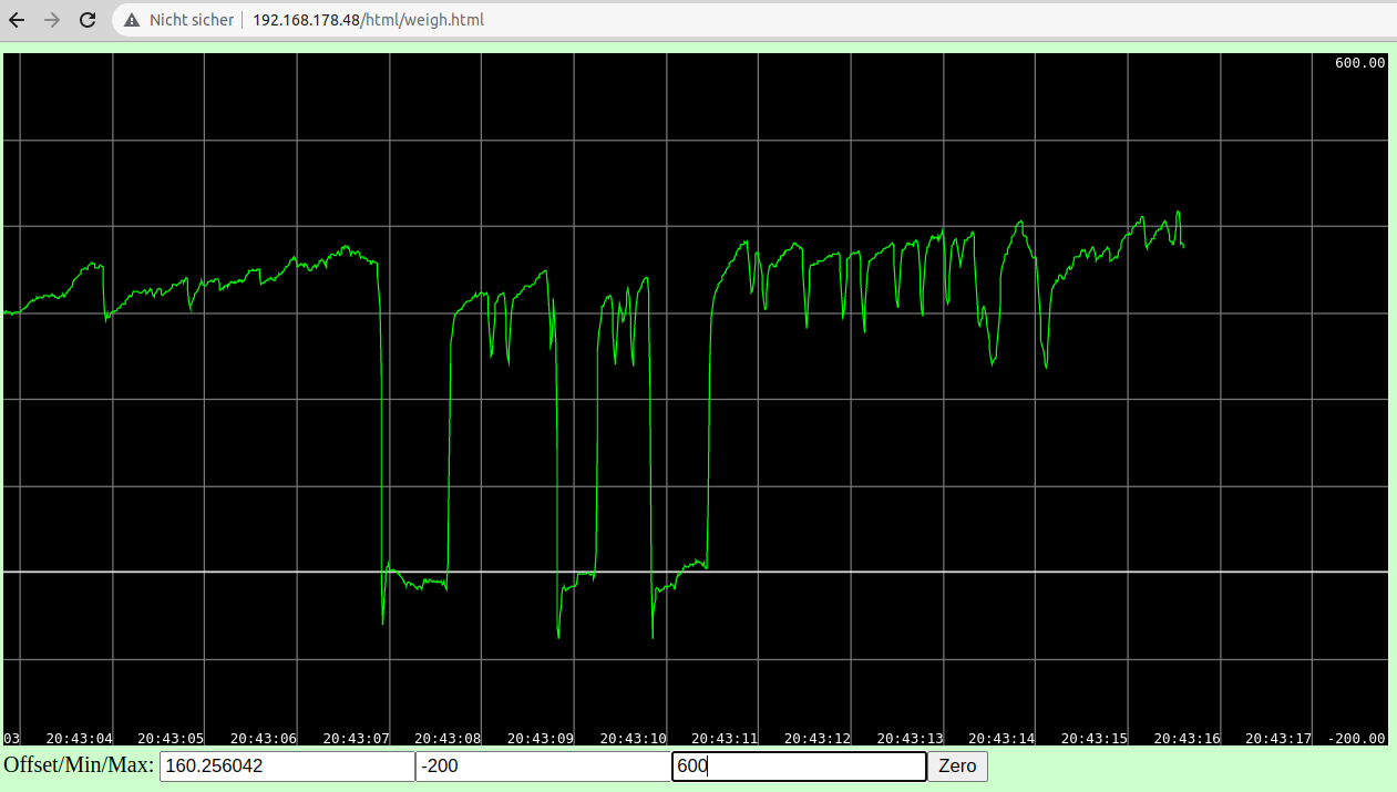

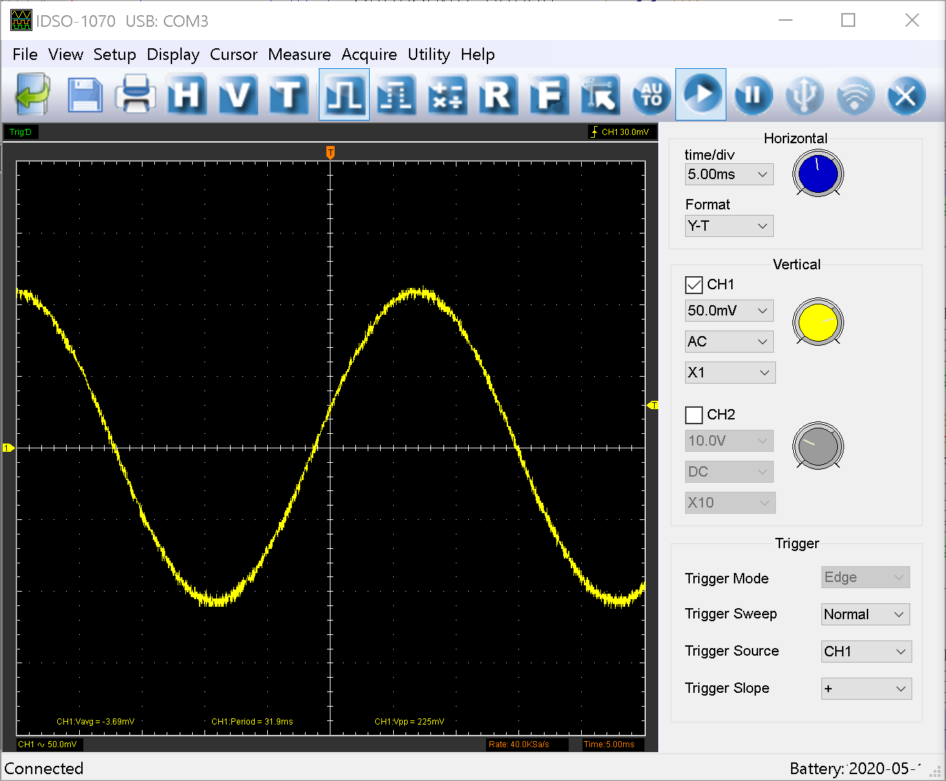
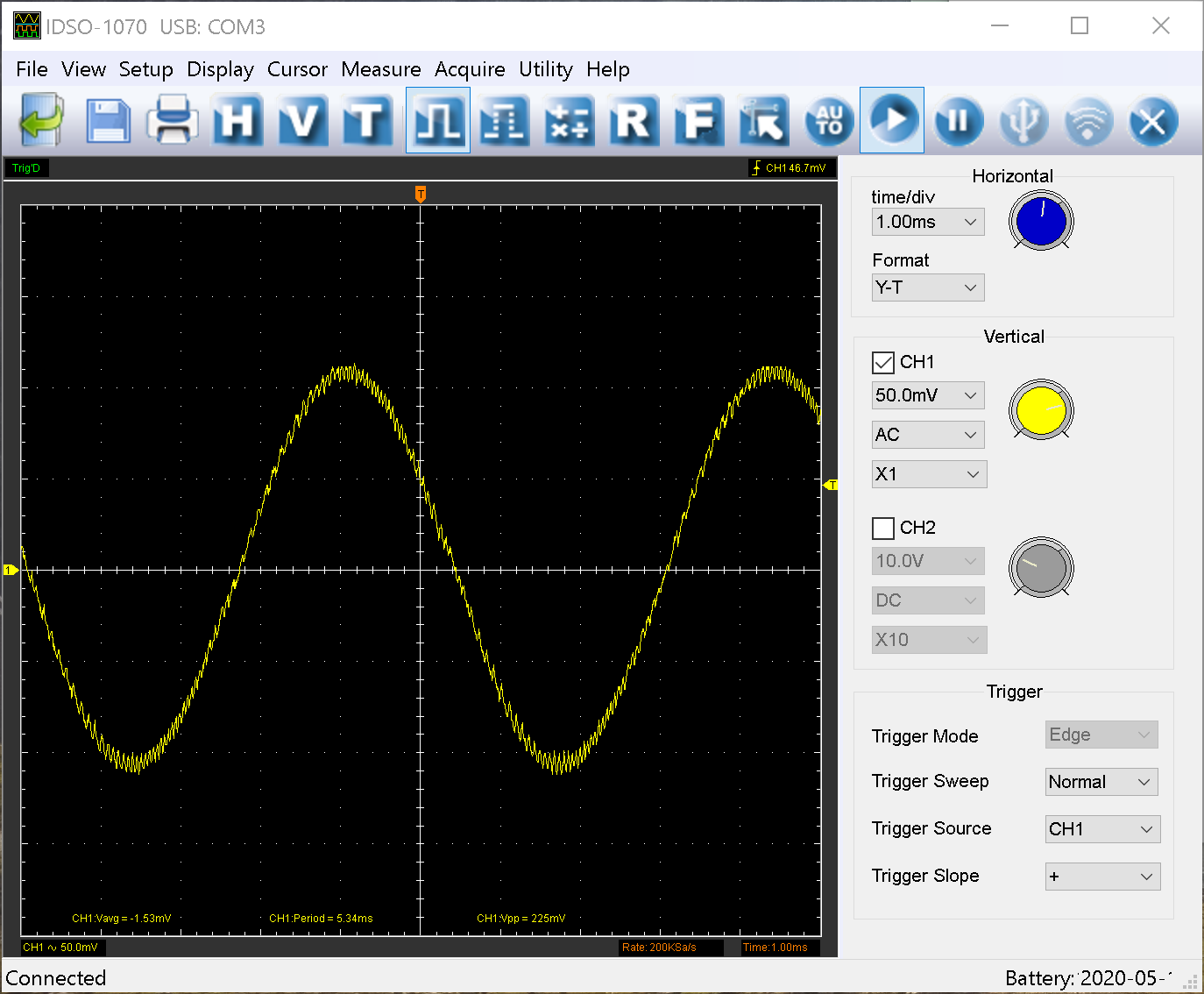
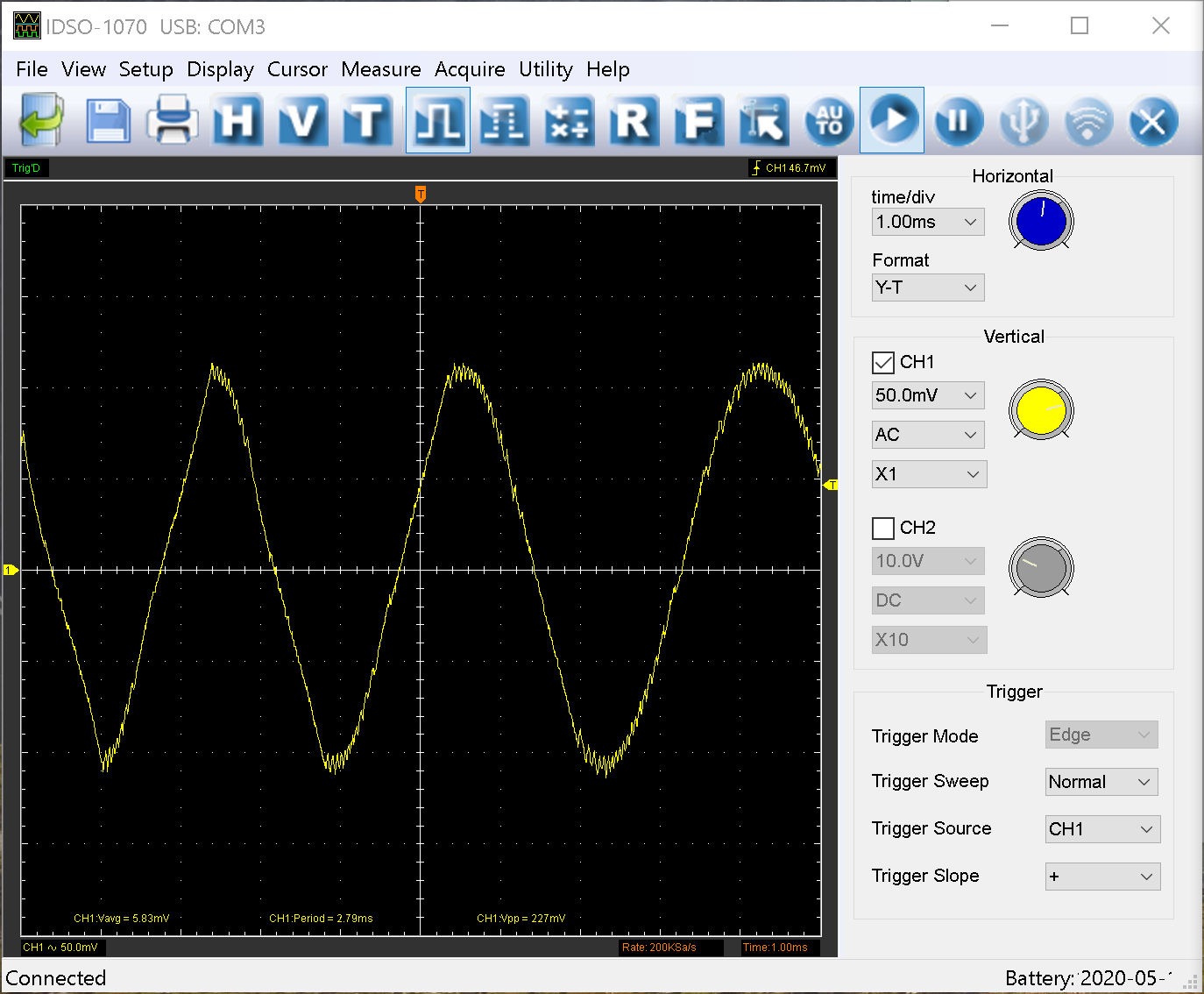
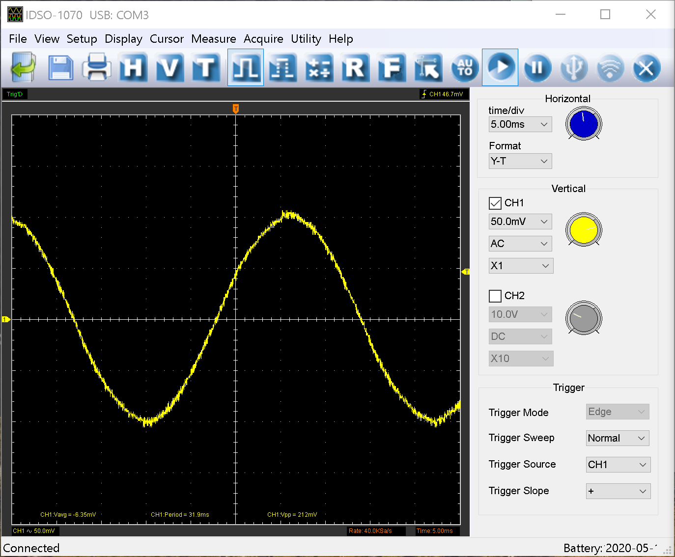
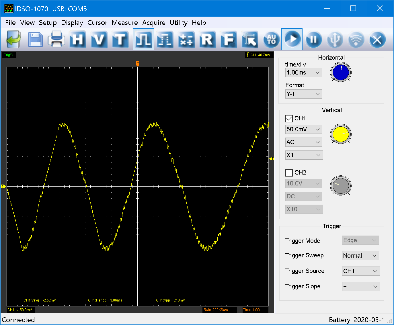
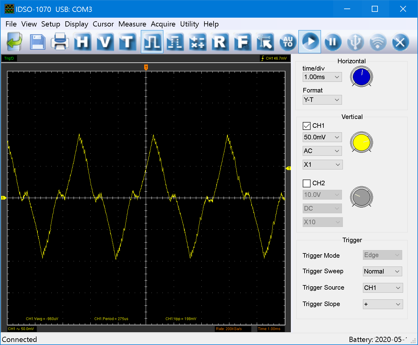
") ) part of the sine wave gets a bit chopped of output 1.
) part of the sine wave gets a bit chopped of output 1.