@droftarts
Here is USB Power.
M122
=== Diagnostics ===
RepRapFirmware for Duet 3 MB6XD version 3.4.2rc1 (2022-07-06 16:23:35) running on Duet 3 MB6XD v0.1 (standalone mode)
Board ID: 08DLM-956DA-M2NS4-6J9DJ-3SD6P-TT3GT
Used output buffers: 3 of 40 (15 max)
=== RTOS ===
Static ram: 149592
Dynamic ram: 95852 of which 0 recycled
Never used RAM 105228, free system stack 206 words
Tasks: NETWORK(ready,28.2%,272) ETHERNET(notifyWait,0.4%,173) HEAT(notifyWait,0.0%,373) Move(notifyWait,0.0%,352) CanReceiv(notifyWait,0.0%,944) CanSender(notifyWait,0.0%,374) CanClock(delaying,0.0%,343) MAIN(running,71.1%,951) IDLE(ready,0.4%,29), total 100.0%
Owned mutexes:
=== Platform ===
Last reset 00:00:33 ago, cause: power up
Last software reset at 2024-05-10 13:27, reason: User, GCodes spinning, available RAM 105156, slot 0
Software reset code 0x0003 HFSR 0x00000000 CFSR 0x00000000 ICSR 0x00400000 BFAR 0x00000000 SP 0x00000000 Task MAIN Freestk 0 n/a
Error status: 0x00
Step timer max interval 1435
MCU temperature: min 38.8, current 61.6, max 61.7
Supply voltage: min 0.1, current 0.2, max 0.2, under voltage events: 0, over voltage events: 0, power good: yes
12V rail voltage: min 0.2, current 0.2, max 0.3, under voltage events: 0
Heap OK, handles allocated/used 0/0, heap memory allocated/used/recyclable 0/0/0, gc cycles 0
Events: 0 queued, 0 completed
Driver 0: ok
Driver 1: ok
Driver 2: ok
Driver 3: ok
Driver 4: ok
Driver 5: ok
Date/time: 2024-05-16 10:09:51
Slowest loop: 3.34ms; fastest: 0.05ms
=== Storage ===
Free file entries: 10
SD card 0 detected, interface speed: 25.0MBytes/sec
SD card longest read time 5.2ms, write time 0.0ms, max retries 0
=== Move ===
DMs created 125, segments created 0, maxWait 0ms, bed compensation in use: none, comp offset 0.000
=== MainDDARing ===
Scheduled moves 0, completed 0, hiccups 0, stepErrors 0, LaErrors 0, Underruns [0, 0, 0], CDDA state -1
=== AuxDDARing ===
Scheduled moves 0, completed 0, hiccups 0, stepErrors 0, LaErrors 0, Underruns [0, 0, 0], CDDA state -1
=== Heat ===
Bed heaters -1 -1 -1 -1 -1 -1 -1 -1 -1 -1 -1 -1, chamber heaters -1 -1 -1 -1, ordering errs 0
=== GCodes ===
Segments left: 0
Movement lock held by null
HTTP is idle in state(s) 0
Telnet is idle in state(s) 0
File is idle in state(s) 0
USB is idle in state(s) 0
Aux is idle in state(s) 0
Trigger is idle in state(s) 0
Queue is idle in state(s) 0
LCD is idle in state(s) 0
SBC is idle in state(s) 0
Daemon is idle in state(s) 0
Aux2 is idle in state(s) 0
Autopause is idle in state(s) 0
Code queue is empty
=== CAN ===
Messages queued 169, received 0, lost 0, boc 0
Longest wait 0ms for reply type 0, peak Tx sync delay 0, free buffers 50 (min 50), ts 169/0/0
Tx timeouts 0,0,168,0,0,0 last cancelled message type 30 dest 127
=== Network ===
Slowest loop: 3.27ms; fastest: 0.02ms
Responder states: HTTP(0) HTTP(0) HTTP(0) HTTP(0) HTTP(0) HTTP(0) FTP(0) Telnet(0), 0 sessions Telnet(0), 0 sessions
HTTP sessions: 1 of 8
- Ethernet -
State: active
Error counts: 0 0 1 0 0
Socket states: 5 2 2 2 2 0 0 0
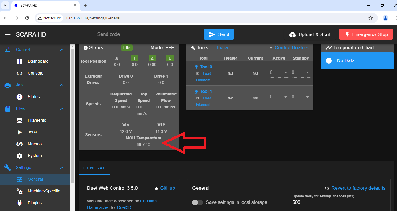
And below is 12v power.
m122
=== Diagnostics ===
RepRapFirmware for Duet 3 MB6XD version 3.4.2rc1 (2022-07-06 16:23:35) running on Duet 3 MB6XD v0.1 (standalone mode)
Board ID: 08DLM-956DA-M2NS4-6J9DJ-3SD6P-TT3GT
Used output buffers: 3 of 40 (15 max)
=== RTOS ===
Static ram: 149592
Dynamic ram: 95852 of which 0 recycled
Never used RAM 105228, free system stack 219 words
Tasks: NETWORK(ready,28.1%,280) ETHERNET(notifyWait,0.1%,184) HEAT(notifyWait,0.0%,373) Move(notifyWait,0.0%,352) CanReceiv(notifyWait,0.0%,944) CanSender(notifyWait,0.0%,374) CanClock(delaying,0.0%,343) MAIN(running,71.0%,978) IDLE(ready,0.8%,29), total 100.0%
Owned mutexes:
=== Platform ===
Last reset 00:00:12 ago, cause: power up
Last software reset at 2024-05-10 13:27, reason: User, GCodes spinning, available RAM 105156, slot 0
Software reset code 0x0003 HFSR 0x00000000 CFSR 0x00000000 ICSR 0x00400000 BFAR 0x00000000 SP 0x00000000 Task MAIN Freestk 0 n/a
Error status: 0x00
Step timer max interval 633
MCU temperature: min 40.6, current 58.5, max 58.6
Supply voltage: min 12.0, current 12.0, max 12.1, under voltage events: 0, over voltage events: 0, power good: yes
12V rail voltage: min 11.3, current 11.3, max 11.4, under voltage events: 0
Heap OK, handles allocated/used 0/0, heap memory allocated/used/recyclable 0/0/0, gc cycles 0
Events: 0 queued, 0 completed
Driver 0: ok
Driver 1: ok
Driver 2: ok
Driver 3: ok
Driver 4: ok
Driver 5: ok
Date/time: 2024-05-16 10:15:48
Slowest loop: 2.36ms; fastest: 0.05ms
=== Storage ===
Free file entries: 10
SD card 0 detected, interface speed: 25.0MBytes/sec
SD card longest read time 5.3ms, write time 0.0ms, max retries 0
=== Move ===
DMs created 125, segments created 0, maxWait 0ms, bed compensation in use: none, comp offset 0.000
=== MainDDARing ===
Scheduled moves 0, completed 0, hiccups 0, stepErrors 0, LaErrors 0, Underruns [0, 0, 0], CDDA state -1
=== AuxDDARing ===
Scheduled moves 0, completed 0, hiccups 0, stepErrors 0, LaErrors 0, Underruns [0, 0, 0], CDDA state -1
=== Heat ===
Bed heaters -1 -1 -1 -1 -1 -1 -1 -1 -1 -1 -1 -1, chamber heaters -1 -1 -1 -1, ordering errs 0
=== GCodes ===
Segments left: 0
Movement lock held by null
HTTP is idle in state(s) 0
Telnet is idle in state(s) 0
File is idle in state(s) 0
USB is idle in state(s) 0
Aux is idle in state(s) 0
Trigger is idle in state(s) 0
Queue is idle in state(s) 0
LCD is idle in state(s) 0
SBC is idle in state(s) 0
Daemon is idle in state(s) 0
Aux2 is idle in state(s) 0
Autopause is idle in state(s) 0
Code queue is empty
=== CAN ===
Messages queued 63, received 0, lost 0, boc 0
Longest wait 0ms for reply type 0, peak Tx sync delay 0, free buffers 50 (min 50), ts 63/0/0
Tx timeouts 0,0,62,0,0,0 last cancelled message type 30 dest 127
=== Network ===
Slowest loop: 1.40ms; fastest: 0.02ms
Responder states: HTTP(0) HTTP(0) HTTP(0) HTTP(0) HTTP(0) HTTP(0) FTP(0) Telnet(0), 0 sessions Telnet(0), 0 sessions
HTTP sessions: 1 of 8
- Ethernet -
State: active
Error counts: 0 0 1 0 0
Socket states: 5 2 2 2 2 0 0 0
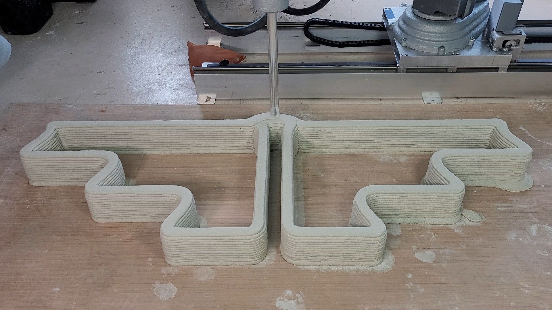
![Final 2.mp4_snapshot_00.30_[2022.04.01_11.35.54].jpg](/assets/uploads/files/1648827385549-final-2.mp4_snapshot_00.30_-2022.04.01_11.35.54.jpg)