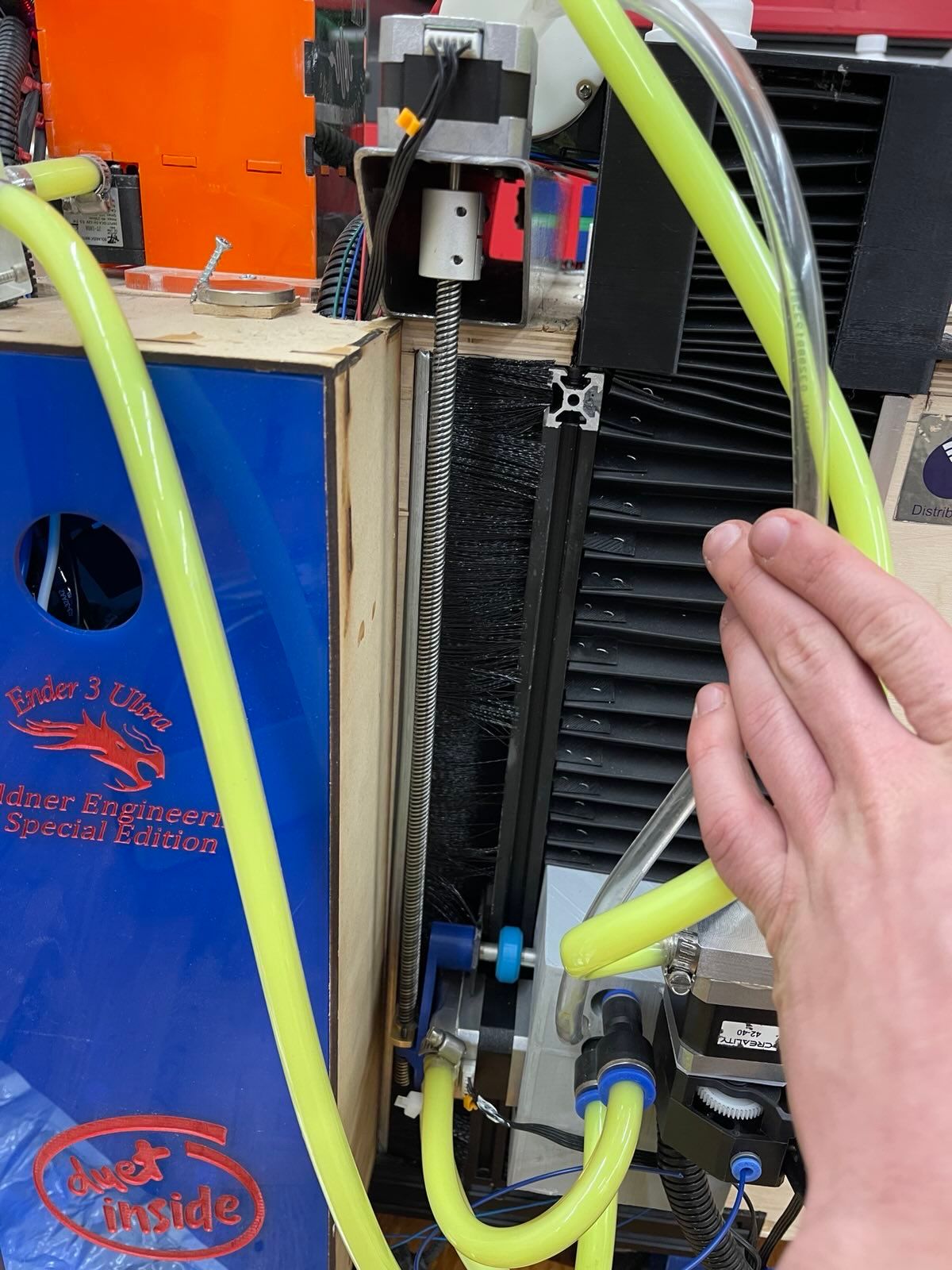
So the way I have my z steppers hooked up the whole x axes hangs on it rather than pushing on it, does this make a difference?
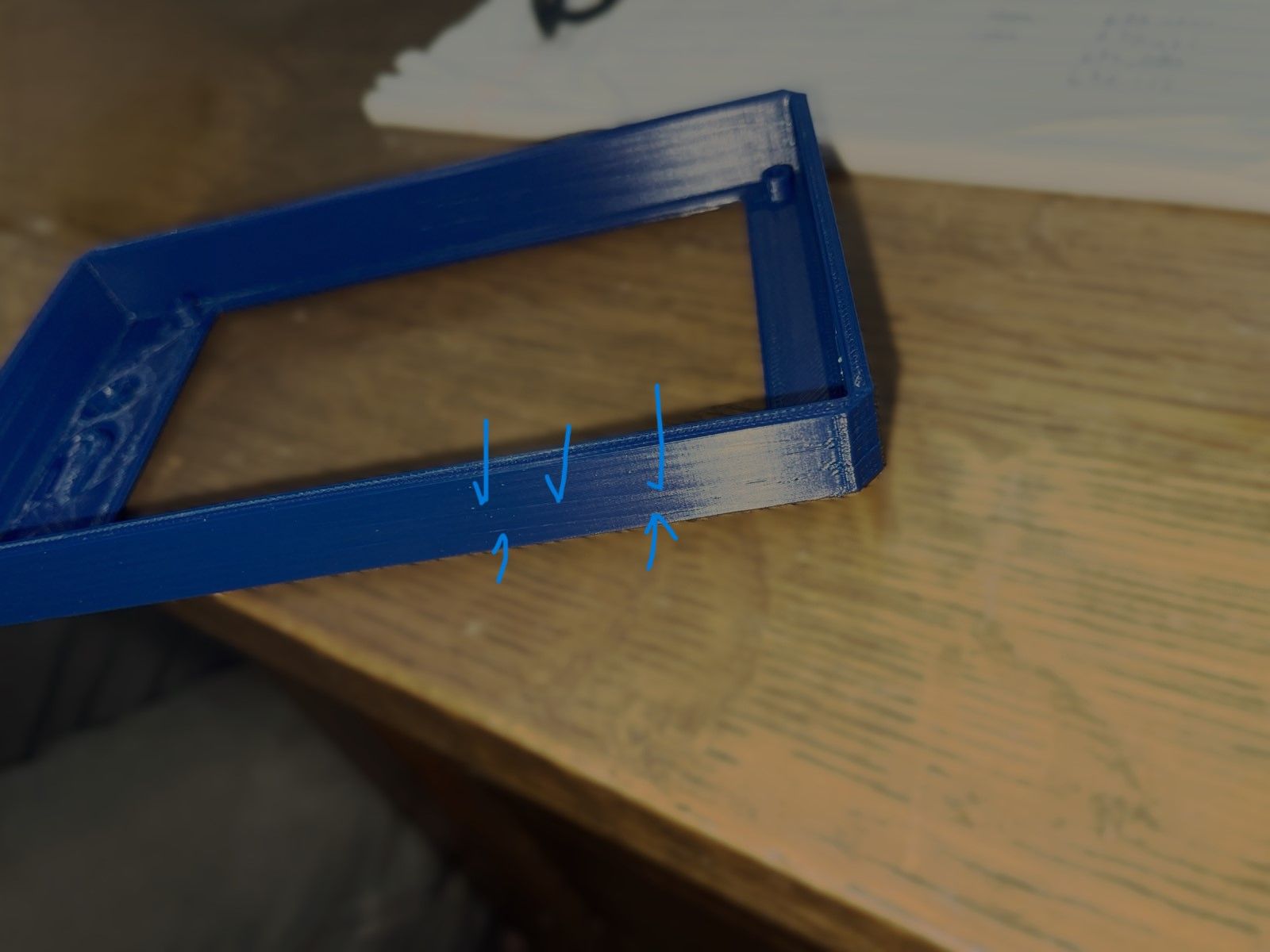
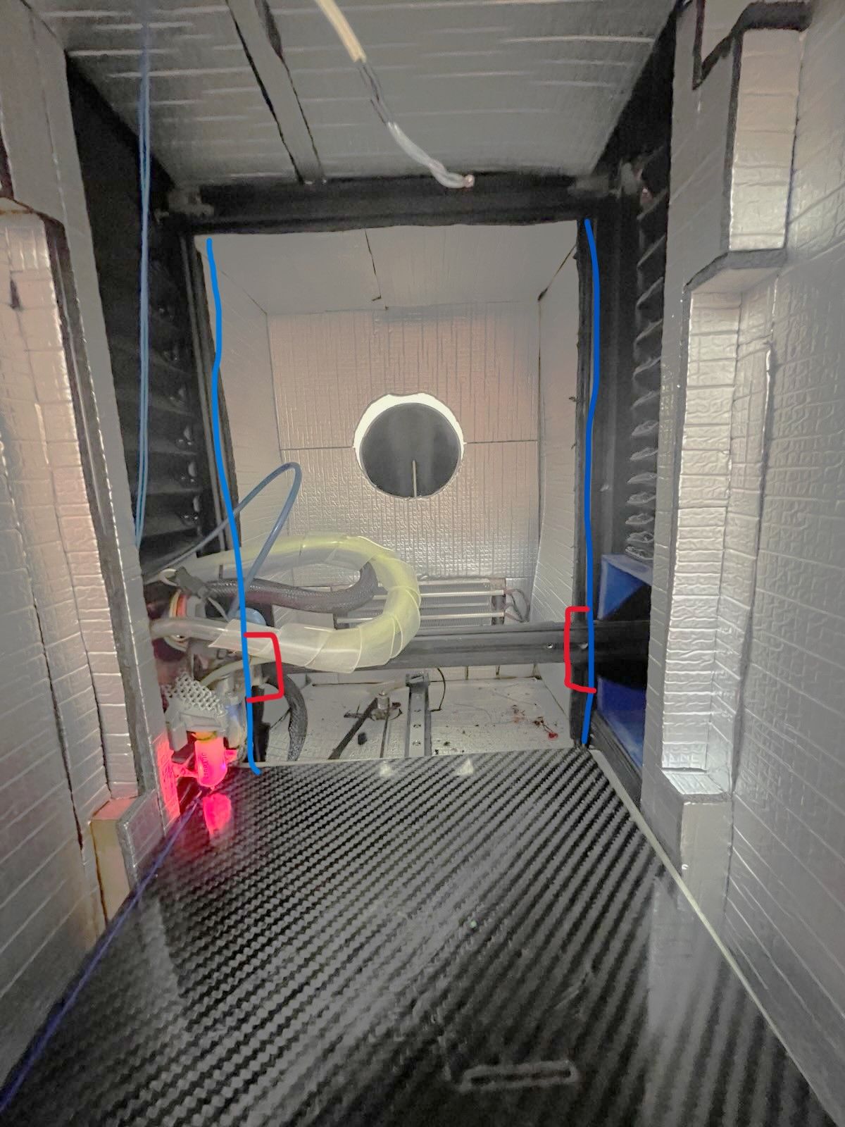 this is how I plan to fix it I will a add linear bearings for the blue lines and then somehow mount the linear bearing cars to the x in a way that it can pivot so it can move independently.
Posts made by 53581
-
RE: diagonal line on print causing layer shifting?posted in Tuning and tweaking
-
RE: diagonal line on print causing layer shifting?posted in Tuning and tweaking
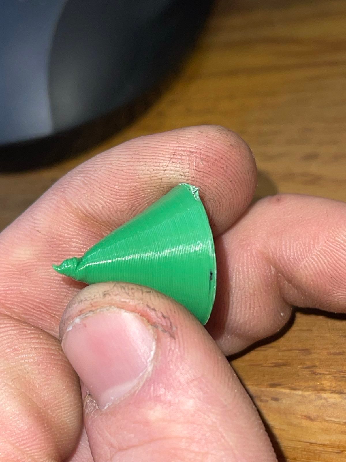
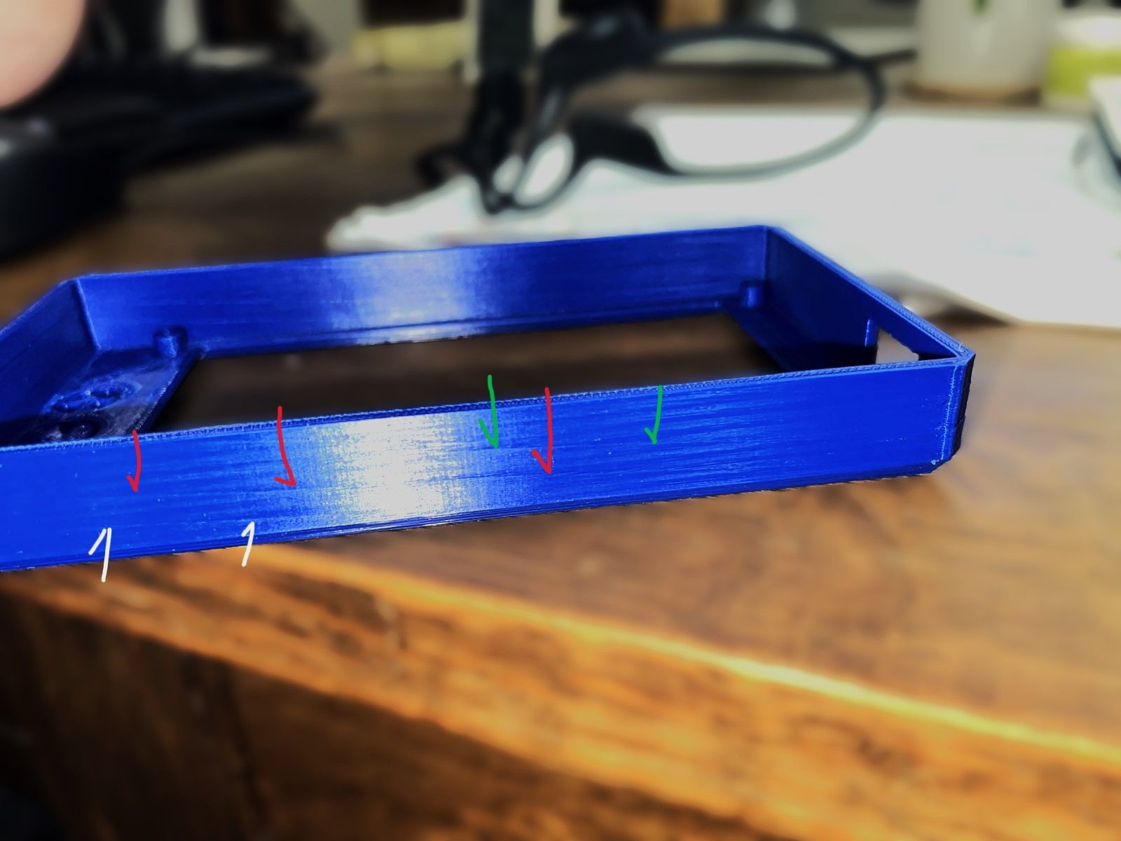
After more testing I Think I am getting z binding on both sides. This would explain why the artifacts do not travel straight through the part but rather make separate patterns on the wall closest to their respective sides while leaving the center looking ok.
-
RE: diagonal line on print causing layer shifting?posted in Tuning and tweaking
@Phaedrux
I think these like pretty good. -
RE: diagonal line on print causing layer shifting?posted in Tuning and tweaking
"What's the smallest Z step your printer can do?" To be honest I am not sure! they are just stock ender 3 stepper Moters. If it is something mechanical, I am not sure how it is consistent enough to travel up the side of the part like that.
-
RE: diagonal line on print causing layer shifting?posted in Tuning and tweaking
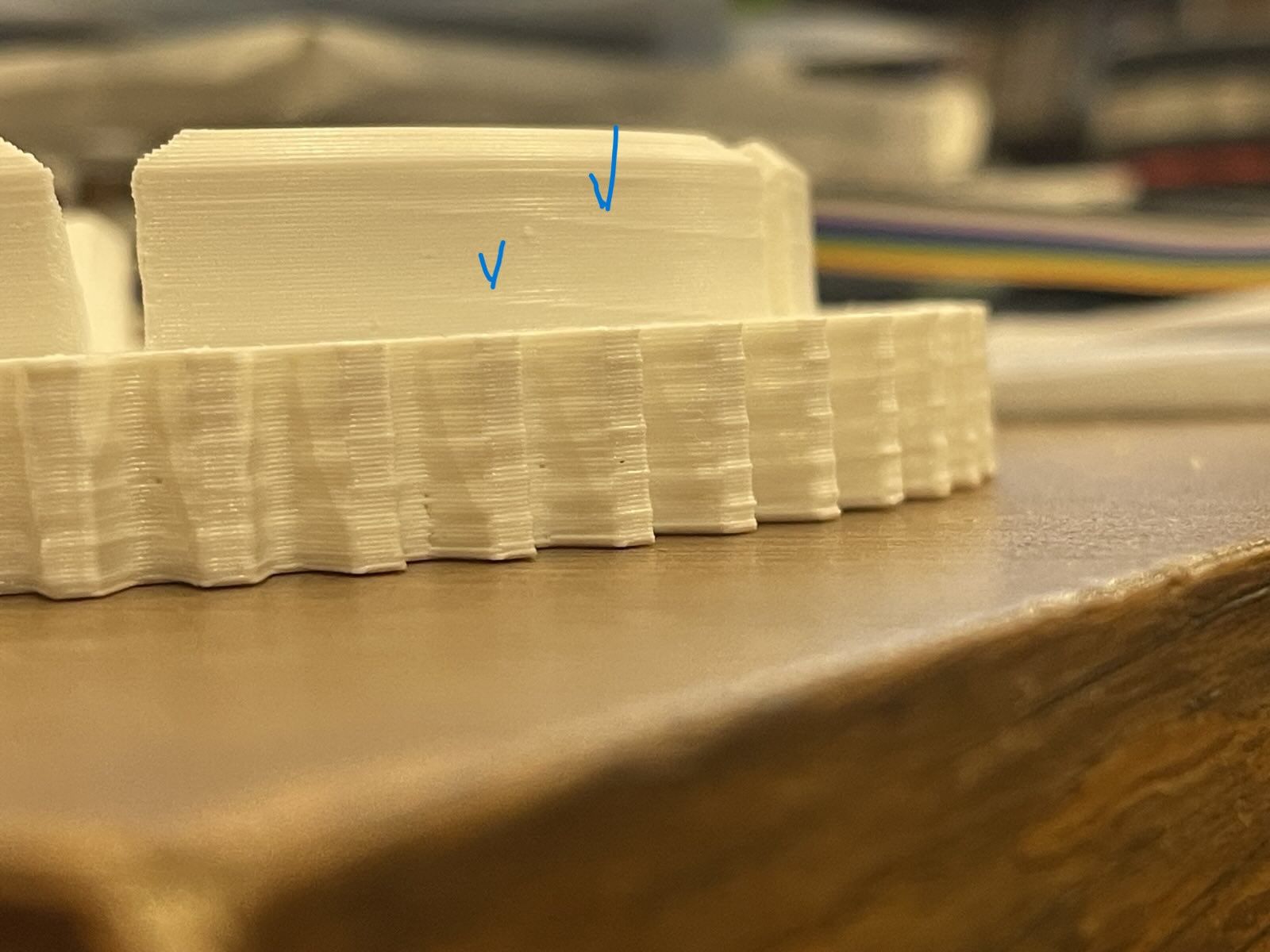
@DIY-O-Sphere I did not even realize I had bang bang on the bed! That would fit with the idea that the layer time effects it. I printed that gear in vase mode, and it was very good. I also tried a Prusa slicer, no change.
-
RE: diagonal line on print causing layer shifting?posted in Tuning and tweaking
@mikeabuilder
If forgot to say it only happens on larger models so I think the z axes can be ruled out.
I use cura so maybe i should try Prusa slicer. Thanks for your ideas! -
RE: diagonal line on print causing layer shifting?posted in Tuning and tweaking
@Phaedrux
It is a bmg with Bowden. -
diagonal line on print causing layer shifting?posted in Tuning and tweaking
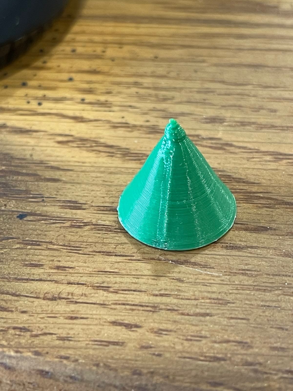
Do you guys have any idea what is causing theses lines. they seem to travel diagonal on the y axes and then leave a small level layer shift only on the x axes. It is on a modded ender 3 with duet 5 mini.
I am not sure whether to blame hardware or software.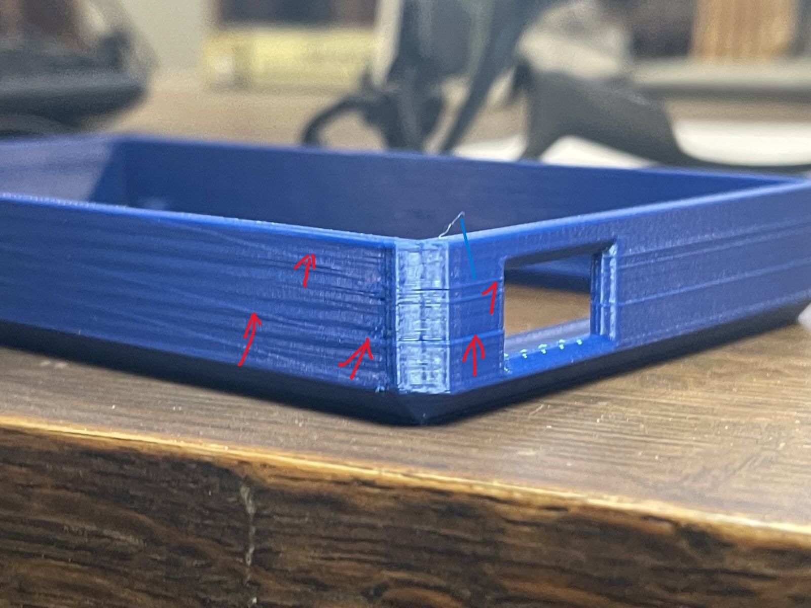
; Configuration file for Duet 3 Mini 5+ (firmware version 3.3) ; executed by the firmware on start-up ; ; generated by RepRapFirmware Configuration Tool v3.3.13 on Wed Oct 12 2022 17:23:19 GMT-0500 (Central Daylight Time) ; General preferences G90 ; send absolute coordinates... M83 ; ...but relative extruder moves M550 P"Ender 3 Ultra" ; set printer name M918 P1 E4 F2000000 ; configure direct-connect display ; Network M552 S1 ; enable network M586 P0 S1 ; enable HTTP M586 P1 S0 ; disable FTP M586 P2 S0 ; disable Telnet ; Drives M569 P0.0 S1 ; physical drive 0.0 goes backwards M569 P0.1 S0 ; physical drive 0.1 goes backwards M569 P0.2 S0 ; physical drive 0.2 goes backwards M569 P0.3 S0 ; physical drive 0.3 goes b M569 P0.4 S0 ; physical drive 0.4 goes backwards M671 X-50:270 Y0:0 S10 ; define dual driven z-axis M584 X0.4 Y0.1 Z0.0:0.2 E0.3 ; set drive mapping M350 X16 Y16 Z16 E16 I1 ; configure microstepping with interpolation M92 X80.6755 Y80.00 Z400 E406.86275 ; set steps per mm M566 X400 Y400 Z60.00 E300.00 ; set maximum instantaneous speed changes (mm/min) M203 X6000.00 Y6000.00 Z600.00 E3600.00 ; set maximum speeds (mm/min) M201 X500 Y500 Z200.00 E500 ; set accelerations (mm/s^2) M906 X1300 Y1400 Z700 E900 I30 ; set motor currents (mA) and motor idle factor in per cent M84 S30 ; Set idle timeout ; Axis Limits M208 X0 Y0 Z0 S1 ; set axis minima M208 X205 Y220 Z260 S0 ; set axis maxima M206 X0 Y20 Z0 ; Endstops M574 X1 S1 P"io5.in" ; configure switch-type (e.g. microswitch) endstop for low end on X via pin io5.in M574 Y1 S1 P"io6.in" ; configure switch-type (e.g. microswitch) endstop for low end on Y via pin io6.in M574 Z1 S2 ; configure Z-probe endstop for low end on Z ; Z-Probe M950 S0 C"io3.out" ; create servo pin 0 for BLTouch M558 P9 C"io3.in" H5 F120 T6000 ; set Z probe type to bltouch and the dive height + speeds G31 P500 X0 Y-20.701 Z3.895 ; set Z probe trigger value, offset and trigger height M556 S50 X0 Y0 Z0 ; set orthogonal axis compensation parameters M557 X10:200 Y10:210 s60:60 ; define me ; Heaters M308 S0 P"temp0" Y"thermistor" T100000 B4092 ; configure sensor 0 as thermistor on pin temp0 M950 H0 C"out0" T0 ; create bed heater output on out0 and map it to sensor 0 M307 H0 B1 S1.00 ; enable bang-bang mode for the bed heater and set PWM limit M140 H0 ; map heated bed to heater 0 M143 H0 S180 ; set temperature limit for heater 0 to 180C M308 S1 P"temp1" Y"pt1000" ; configure sensor 1 as PT1000 on pin temp1 M950 H1 C"out1" T1 ; create nozzle heater output on out1 and map it to sensor 1 M307 H1 B0 S1.00 ; disable bang-bang mode for heater and set PWM limit M143 H1 S450 ; set temperature limit for heater 1 to 450C M308 S2 P"temp2" Y"thermistor" T100000 B4092 ; configure sensor 2 as thermistor on pin temp2 M950 H2 C"out2" T2 ; create chamber heater output on out2 and map it to sensor 2 M307 H2 B1 S50 ; enable bang-bang mode for the chamber heater and set PWM limit M141 H2 ; map chamber to heater 2 M143 H2 S100 ; set temperature limit for heater 2 to 100C ; Fans M950 F0 C"out3" Q150 ; create fan 0 on pin out3 and set its frequency M106 P0 C"part fan " S0 H-1 ; set fan 0 name and value. Thermostatic control is turned off M950 F1 C"out4" Q500 ; create fan 1 on pin out4 and set its frequency M106 P1 C"hotend fan" S1 H1:2:0 T45 ; set fan 1 name and value. Thermostatic control is turned on M950 F2 C"out5" Q500 ; create fan 2 on pin out5 and set its frequency M106 P2 C"mother bourd" S1 H1:2:0 T45 ; set fan 2 name and value. Thermostatic control is turned on ; Tools M563 P0 S"Copperhead" D0 H1 F0 ; define tool 0 G10 P0 X0 Y0 Z0 ; set tool 0 axis offsets G10 P0 R0 S0 ; set initial tool 0 active and standby temperatures to 0C ; Custom settings are not defined ; Miscellaneous M501 ; load saved parameters from non-volatile memory M911 S22 R23 P"M913 X0 Y0 G91 M83 G1 Z3 E-5 F1000" ; set voltage thresholds and actions to run on power loss T0 ; select first tool M955 P0 C"spi.cs2+spi.cs1" ; all wires connected to temp DB connector, no temperature daughterboard M572 D0 S.6 M556 S100 X-0.2 ;skew adjust ;M593 P"EI3" F40 ; use ZVD input shaping to cancel ringing at 40.5Hz M376 H10 M304 P32.8 I.706 D111.9 M575 P1 S1 B57600;screen code -
RE: BLTouch not communicating with my 3 miniposted in Duet Hardware and wiring
all right I did figure out this problem finally. the deploy probe file was messed up, I'm not sure how it slowly got worse and worse but is now working! I do have one more question however, I am geting this error and I do not know what's wrong does anyone here have answer?
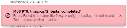
thank you for your help! -
RE: BLTouch not communicating with my 3 miniposted in Duet Hardware and wiring
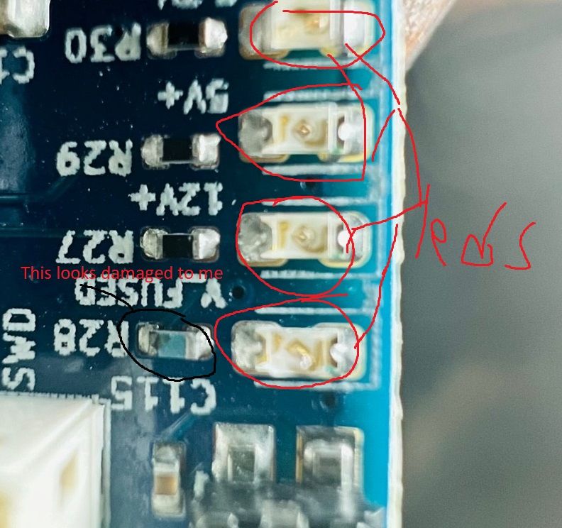
I don't know what that chip is though.
Does my config look fine? -
RE: BLTouch not communicating with my 3 miniposted in Duet Hardware and wiring
Is there something on the board that all I/O pins other than 5 and 6 have in common that could have fried?
-
RE: BLTouch not communicating with my 3 miniposted in Duet Hardware and wiring
@Phaedrux
So I clean the board and above the lights on the board it pretty bad but it clean up very well and I could even tell anything was amiss when I was done. So what do I do from here just buy a new board or is there a way I can pinpoint it more? -
RE: BLTouch not communicating with my 3 miniposted in Duet Hardware and wiring
@53581
I tested my wires and they are good but I have not tried cleaning the board yet.
I have also test from different computer with no results. Thanks again.Also If the board is bad is there anybody that would repair it?
-
RE: BLTouch not communicating with my 3 miniposted in Duet Hardware and wiring
@Phaedrux said in BLTouch not communicating with my 3 mini:
or another computer to test the BLtouch on?
you mean try it form a different computer via DWC? thank you!
-
RE: BLTouch not communicating with my 3 miniposted in Duet Hardware and wiring
I was using a 3DTouch and I switch from that to a ANTCLABS BLTouch and it did not help.
-
RE: BLTouch not communicating with my 3 miniposted in Duet Hardware and wiring
@Phaedrux Yes I did. Thanks for working with me!


