Hi All
I'm really bringing this post back from the dead!
Was there any progression on the use of your non-contact sensor through the Duet system? I am wanting to implement something similar for myself.
Thanks
Hi All
I'm really bringing this post back from the dead!
Was there any progression on the use of your non-contact sensor through the Duet system? I am wanting to implement something similar for myself.
Thanks
Hello Droftarts and DC42
Apologies for the long reply. I was not receiving notifications from these posts as I used to and did not see your replies.
; Filament Sensor
; M591 D0 P3 C4 S1 R80:120 L26.32 E3.0                   ; filament sensor for extruder 0, enabled, sensitivity 26.32mm.rev, 80% to 120% tolerance, 3mm detection length
I have not had time to play with the setup any further but from the looks of things, the filament is nicely held in the hobbed groove. I may re-print the housing with our Form 2 SLA printer and see if that helps with the alignment of the idle wheel.
Kind Regards
Benjamin Norton
Is anyone able to weigh in on this issue?
Hi All
I am trying to set up the sensor-less homing on my Duet 2/Duex5 controlled printer and am so far have had some issues in that the bed drives into the ends of the Z-Axis assemblies and skips steps but does not sense them.
I am wanting to use the sensor-less homing to do a 'gross' homing of the ball-screw driven Z-Axis actuators which are prone to falling under the weight of the bed when the motors are idled which leaves the bed on a bad angle. This does not cause any damage as the bed is mounted with ball and socket joints. After this gross homing is completed, the printer will then use the BL-Touch probe and the independently driven Z-Axis actuators to to the more accurate bed levelling (G32).
I have setup a testing macro that is essentially a modified 'homeall' sequence. The G32 would be added in later.
G91                                  ; relative positioning
G1 Z10 F6000 S2                      ; lift Z relative to current position
G1 S1 X480 Y475 F9000                ; move quickly to X and Y axis endstops and stop there (first pass)
G1 X-5 Y-5 F6000                     ; go back a few mm
G1 S1 X480 Y475 F360                 ; move slowly to X and Y axis endstops once more (second pass)
M400                                                   ; make sure everything has stopped before we make changes
M915 P2:5:6 S-30 F0 H250 R0                            ; Configure Z-Axis Stall Detection
M584 X0 Y1:7 Z2 U5 V6 E3 P5                            ; Separate Z-Axis Lead screws and drive independently
M913 Z50 U50 V50                                       ; Lower motor current by 50%
M574 Z1 U1 V1 S3                                       ; Configure Z-Axis stall detection homing
G91                                                    ; relative positioning
G1 S1 Z-650 U-650 V-650 F500                           ; Home Z-Axis actuators independently
M400                                                   ; make sure everything has stopped before we make changes
M913 Z100 U100 V100                                    ; Reset motor current
M584 X0 Y1:7 Z2:5:6 U5 V6 E3 P3                        ; Reset drive mapping
M574 Z1 S2                                             ; Reset Z-Axis to be controlled by probe
G90                                  ; absolute positioning
G1 Z10 F6000 S2                      ; lift Z relative to current position
G1 X220 Y197.5 F9000                 ; go to first bed probe point
M558 F400                            ; adjust first probe speed
G30                                  ; home Z by probing the bed
M558 F120                            ; reset probe speed
G30                                  ; home Z by probing the bed
My config configures the rest of the U and the V axes:
; Drives
M569 P0 S0                                           ; X drive goes backwards
M569 P1 S0                                           ; Y1 drive goes backwards
M569 P2 S0                                           ; Z1 drive goes backwards
M569 P3 S1                                           ; E0 drive goes forwards
M569 P5 S0                                           ; Z2 drive goes backwards
M569 P6 S0                                           ; Z3 drive goes backwards
M569 P7 S1                                           ; Y2 drive goes forwards

M584 X0 Y1:7 Z2:5:6 U5 V6 E3 P3                      ; Apply custom drive mapping, U is a dummy Axis and P3 is setting the number of visible axes
M671 X222:-10:520 Y581:25:25 S10.0                   ; leadscrews at rear middle, front left and rear right

M350 X16 Y16 Z16 U16 V16 E16 I1                                 ; Configure microstepping with interpolation
M92 X160 Y80 Z320.00 U320.00 V320.00 E946.00                    ; Set steps per mm
M566 X900.00 Y900.00 Z12.00 U12.00 V12.00 E120.00               ; Set maximum instantaneous speed changes (mm/min)
M203 X10000.00 Y10000.00 Z400.00 U400.00 V400.00 E1200.00       ; Set maximum speeds (mm/min)
M201 X1000.00 Y1000.00 Z20.00 U20.00 V20.00 E250.00             ; Set accelerations (mm/s^2)
M906 X1000.00 Y1500.00 Z1500.00 U1500.00 V1500.00 E1200.00 I100 ; Set motor currents (mA) and motor idle factor in per cent

M84 S0                                                          ; Set idle timeout (0 is disable a time out, always on )

; Axis Limits
M208 X0 Y0 Z-0.5 U-0.5 U-0.5 S1                      ; Set axis minima
M208 X470 Y465 Z650 U650 V650 S0                     ; Set axis maxima

; Endstops
M574 X2 Y2 S1                                        ; Set active high endstops

; Z-Probe
M574 Z1 S2                                           ; Set endstops controlled by probe
M307 H3 A-1 C-1 D-1                                  ; Disable heater on PWM channel for BLTouch
M558 P9 H5 F120 T9000 X0 Y0 Z1                       ; Set Z probe type to bltouch and the dive height + speeds
G31 P500 X25.4 Y0.2 Z0.847                           ; Set Z probe trigger value, offset and trigger height
M557 X25.4:435 Y10.2:440 P5                          ; Define mesh grid
Any help would be greatly appreciated
Hi All
Hardware:
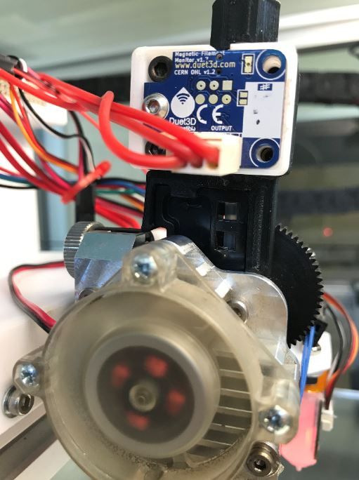
We have recently purchased a Duet Rolling Magnet Sensor for the intention to use it with 2.85mm filament, mostly 85A Ninjaflex. We have successfully reverse engineered the 1.75mm housing and adapted it to fit the larger filament.
After successfully connecting the sensor to our Duet 2, we have began to receive readings while running test prints which are less than ideal, min 87%, max 113% over 581.2mm, and are hoping to improve upon this. My thinking is that the sensor is trying to measure filament retractions which isn't read accurately with the flexible filament(?). I have calibrated the sensor as accurately as possible.
Has anyone successfully adapted the 1.75mm sensor to fit 2.85mm filament?
Thanks for all of help.
Hi Pheadrux
Yes, it does work from the always on fans and I have tried to adjust the Signal Inversion.
I am starting to think that it is the fan that I am trying to use. It is a Cera Dyna ATX Radial fan.
I will try come different fans and hopefully they will work.
Thanks for the help!
Hi All
Once again, there is another person struggling to configure their Print Cooling Nozzle Fan. I have read all of the other posts regarding this issue but still have not succeeded. I have my nozzle fan connected to Fan0 on my Duet 2 Wifi (2.02 Firmware) and Heatsink fan on Fan1.
So far, I have tried adjusting the blip time, changing the frequency, tried different Fan connections, re configuring tool settings and just about everything else.
I understand that Fan0 is set for PWM on the nozzle fan by default and tried to run the fan with no config settings for it, but I figure it wouldn't hurt to put it back in (whether its a good idea or not).
My Config.g is below:
*; Fans
M106 P0 S1 I0 F500 H-1 B1 ; Set fan 0 value, PWM signal inversion and frequency. Thermostatic control is turned off
M106 P1 S1 I0 F500 H4 T30:55 ; Set fan 1 value, PWM signal inversion and frequency. Thermostatic control is turned on
M106 P6 S1 F500 ; configure fan 6 as always on
M106 P7 S1 F500 ; configure fan 7 as always on
; Tools
M563 P0 S"Nozzle 1" D0 H1 ; Define tool 0
G10 P0 X0 Y0 Z0 ; Set tool 0 axis offsets
G10 P0 R0 S0 ; Set initial tool 0 active and standby temperatures to 0C*
Thank you all for the help.
Hi Guys
I am wanting to run a Rolling Magnet Filament Monitor with 2.85mm clear TPU filament but I have seen that it is only available for 1.75mm filament. Is there a way this can be done? Is it possible to alter the housing to allow for the larger diameter?
Thanks for all the help
Ben N
@deckingman
That makes sense now. I just figured each endstop input would pair up with the corresponding motor output and I didn't look too much into it! Thanks for all of the help.
@dc42
I did have the second Y Axis endstop connected to the E4 Endstop input on the Duex Board and not E0. I swapped them over and It seemed to do the job! Why would that be necessary? Wouldn't the endstops be married to their stepper output?
Thank you for all of the help