Duet3D Logo Duet3D
    • Tags
    • Documentation
    • Order
    • Register
    • Login
    1. Home
    2. CHarding
    • Profile
    • Following 0
    • Followers 0
    • Topics 6
    • Posts 14
    • Best 0
    • Controversial 0
    • Groups 0

    CHarding

    @CHarding

    0
    Reputation
    7
    Profile views
    14
    Posts
    0
    Followers
    0
    Following
    Joined Last Online

    CHarding Unfollow Follow

    Latest posts made by CHarding

    • RE: Duet3D mini5+ - wiring for Bondtech LGX Lite?

      @ droftarts @deckingman Thank you for your input.

      The main issue was that the cabling on my version of the LDO motor (which I bought in late 2022) is "unusual". On my YRBG (Yellow, Red, Blue, Green) cabeling, YR should be one pair and BG the other.

      (Note that the colors of my LDO, do NOT match the colors used on the RevA spec sheet: https://www.bondtech.se/downloads/TDS/HT-LDO-36STH20-1004AHG(XH)-RevA.pdf !)

      However, after using the short-out-a-pair method for establishing the pairs from here: https://docs.duet3d.com/User_manual/Connecting_hardware/Motors_connecting it turns out that the two pairs in fact are GR and YB! The following mapping of the cables to the A+/A- B+/B- notation the Duet board uses seems to work:

      A+ => Green
      A- => Red
      B+ => Yellow
      B- => Blue
      

      (Note: there maybe other valid mappings, this is just the first one I tried and it works for me)

      Cheers

      Chris

      posted in Duet Hardware and wiring
      CHardingundefined
      CHarding
    • Duet3D mini5+ - wiring for Bondtech LGX Lite?

      Hi!

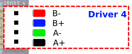
      I'm trying to figure out how to wire the four cables from the LGX Lite stepper motor (Yellow, Red, Blue, Green) to the four pins on the mini 5+ board (Red=B-, Blue=B+, Green=A- and Black=A+). Would anybody who has done this be willing to share which goes where?

      Thanks!

      LGX Lite wiring:
      1378b984-e0d9-4e0b-854b-e19bbc95d060-image.png

      Duet3D wiring:
      d3c7011c-f1a5-43de-8758-ba5198d10f76-image.png

      posted in Duet Hardware and wiring
      CHardingundefined
      CHarding
    • RE: Super weird gcode bug(?) on Duet3D (Anycubic Kossel plus)

      So would reducing this a bit, so say 105 mm and putting that also into the Cura printer dimensions solve all this?

      posted in General Discussion
      CHardingundefined
      CHarding
    • RE: Super weird gcode bug(?) on Duet3D (Anycubic Kossel plus)

      Here's the config file.

      M665 L268.031:268.031:268.031 R133.912 H290.834 B105.0 X-0.770 Y0.406 Z0.000

      Radius seems large enough, but you were correct, it can't actually physically reach that corner!

      THANKS!

      ; executed by the firmware on start-up
      ;
      ; generated by RepRapFirmware Configuration Tool on Thu Jul 12 2018 20:54:00 GMT-0500 (Central Daylight Time)
      
      ; General preferences
      G90                                                ; Send absolute coordinates...
      M83                                                ; ...but relative extruder moves
      
      ; Without calibration
      M665 L268.031:268.031:268.031 R134.201 H295 B120.0                      ; Set delta radius, diagonal rod length, printable radius and homed height
      M666 X0 Y0 Z0                                      ; Put your endstop adjustments here, or let auto calibration find them


      ;*** The homed height is deliberately set too high in the following - you will adjust it during calibration.
      
      
      ; with 6,7,8 params https://duet3d.dozuki.com/Wiki/Calibrating_a_delta_printer#Section_Setting_up_the_bed_g_file
      M665 L268.031:268.031:268.031 R133.912 H290.834 B105.0 X-0.770 Y0.406 Z0.000
      M666 X0.692 Y-1.982 Z1.290 A-0.19 B-0.51
      
      M665 B110 ; bed radius is 11 cm!
      
      ; Network
      M550 PAnyCubic Kossel Plus Duet3D                   ; Set machine name
      M540  xxxxxxxxxxxxxxxxx             ; MAC Address
      M552 S1                                            ; Enable network


      ;*** Access point is configured manually via M587
      M586 P0 S1                                         ; Enable HTTP
      M586 P1 S0                                         ; Disable FTP
      M586 P2 S0                                         ; Disable Telnet
      
      ; Drives
      M569 P0 S0                                         ; Drive 0 goes forwards CH reversed
      M569 P1 S0                                         ; Drive 1 goes forwards CH reversed
      M569 P2 S0                                         ; Drive 2 goes forwards CH reversed
      M569 P3 S0                                         ; Drive 3 goes forwards. CH reversed
      M350 X16 Y16 Z16 E16 I1                            ; Configure microstepping with interpolation
      M92 X80 Y80 Z80 E96                                ; Set steps per mm
      M566 X300 Y300 Z300 E300                           ; Set maximum instantaneous speed changes (mm/min)
      M203 X12000 Y12000 Z12000 E12000                   ; Set maximum speeds (mm/min)
      M201 X3000 Y3000 Z3000 E3000                       ; Set accelerations (mm/s^2)
      M906 X1000 Y1000 Z1000 E1000 I30                   ; Set motor currents (mA) and motor idle factor in per cent
      M84 S30                                            ; Set idle timeout
      
      ; Axis Limits
      M208 Z-1 S1                                         ; Set minimum Z
      
      ; Endstops
      M574 X2 Y2 Z2 S1                                   ; Set active high endstops
      
      ; Z-Probe
      M558 P4 H2 F300 T8000                        ; Set Z probe type to switch and the dive height + speeds H (was 1.5)
      G31 P1000 X0 Y0 Z15.82              ; Set Z probe trigger value, offset and trigger height, was 16.67 before V6
      M557 R110 S20                                      ; Define mesh grid
      
      ; Filament sensor
      M591 D0 P2 C4 S1 ; P2: low signal when filament present), C4: connect to E1 endstop
      
      ; Heaters
      M305 P0 T100000 B4138 C0 R4700                     ; Set thermistor + ADC parameters for heater 0
      M143 H0 S120                                       ; Set temperature limit for heater 0 to 120C
      M305 P1 T100000 B4729 C7.06e-8 R4700               ; Set thermistor + ADC parameters for heater 1 # E3D V6 lite 
      M143 H1 S250                                       ; Set temperature limit for heater 1 to 250C
      ; PID tune: Heater 1 model: gain 321.9, time constant 165.8, dead time 6.4, max PWM 1.00, calibration voltage 12.9, mode PID, inverted no, frequency default
      Computed PID parameters for setpoint change: P14.4, I0.441, D64
      ; set via config override
      
      
      ; Fans
      M106 P0 S0.3 I0 F500 H-1                           ; Set fan 0 value, PWM signal inversion and frequency. Thermostatic control is turned off
      M106 P1 S1 I0 F500 H1 T45                          ; Set fan 1 value, PWM signal inversion and frequency. Thermostatic control is turned on
      M106 P2 S1 I0 F500 H1 T45                          ; Set fan 2 value, PWM signal inversion and frequency. Thermostatic control is turned on
      
      ; Tools
      M563 P0 D0 H1                                      ; Define tool 0
      G10 P0 X0 Y0 Z0                                    ; Set tool 0 axis offsets
      G10 P0 R0 S0                                       ; Set initial tool 0 active and standby temperatures to 0C
      
      ; Automatic power saving
      M911 S10 R11 P"M913 X0 Y0 G91 M83 G1 Z3 E-5 F1000" ; Set voltage thresholds and actions to run on power loss
      
      ; Custom settings are not configured
      
      ; Miscellaneous
      M501                                               ; Load saved parameters from non-volatile memory
      T0                                                 ; Select first tool
      
      posted in General Discussion
      CHardingundefined
      CHarding
    • Super weird gcode bug(?) on Duet3D (Anycubic Kossel plus)

      Hi!

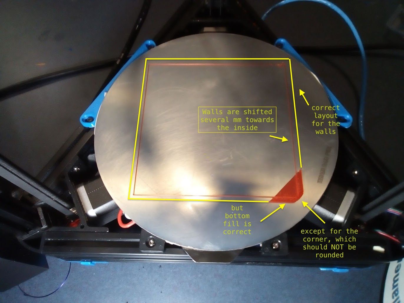
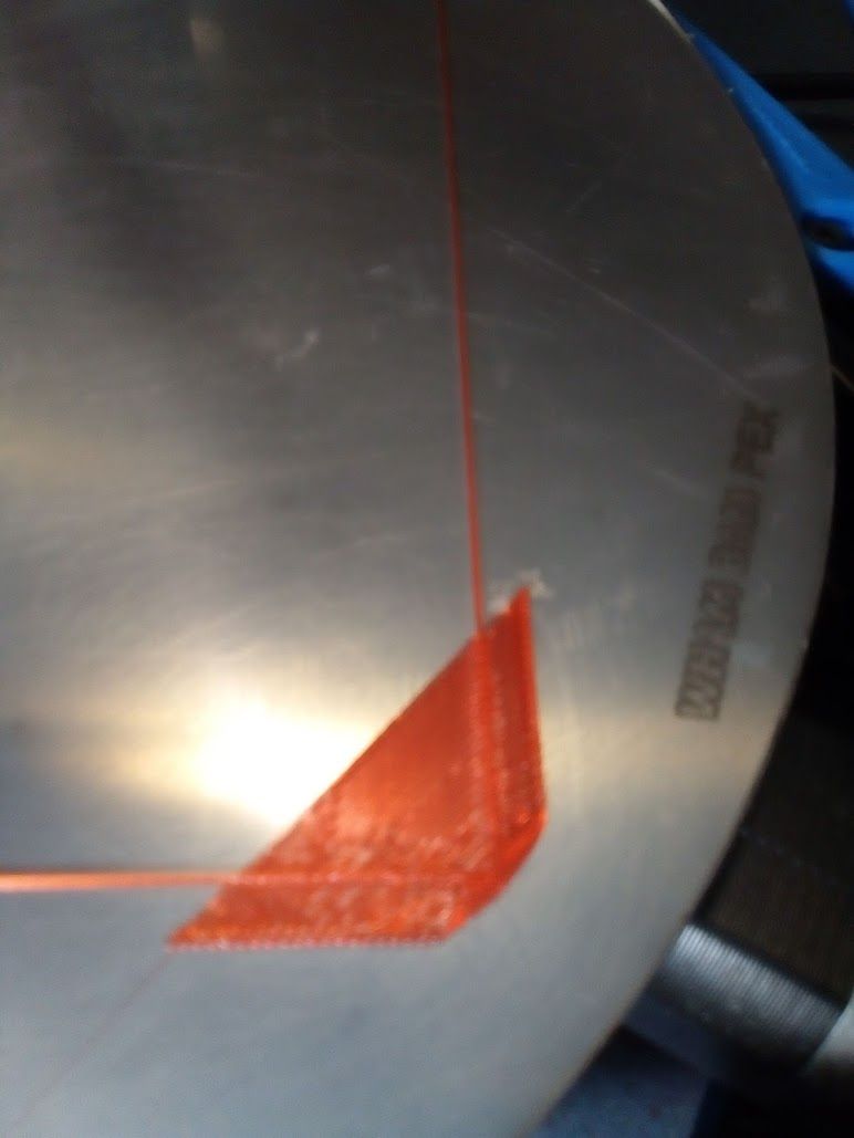
      I'm running firmware 2.05.1 (latest for version 2) on a Anycubic kossel plus. When I print a 160 x 160 mm box (which is pretty large but totally reachable for the nozzle) I get a "bug" where the walls are printed several mm inside (what would be a say 155 x 155 mm box) but the bottom (and later infill and top) layers are printed correctly for 160 x 160 - except the corners are rounded:
      bonkers_walls.jpg
      bonkers_walls_closeup.jpg

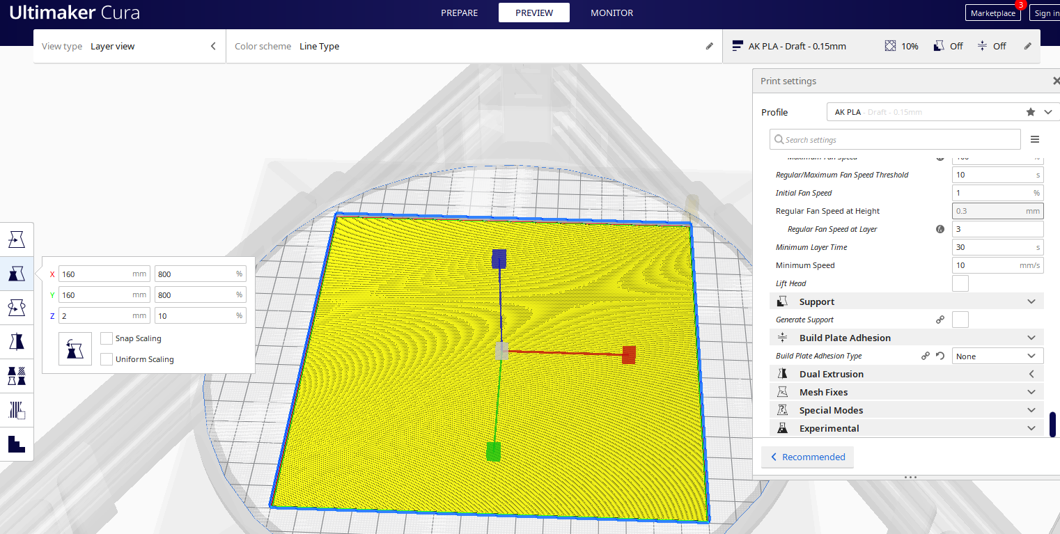
      Now, that could be a Cura 4.8 problem, but the gcode looks fine in Cura:
      bonkers_cura.PNG
      and I've also loaded it into Craftware, where it looks fine, too. Somehow the correct gcode for the walls gets translated a bit towards the inside, and I'm pretty confused as to why that happens.

      This is the gcode:bonkers.gcode

      The rounded corners remind me of the way a brim would look, except I have no brim and no skirt!

      So .... is this a known issue? Was this fixed in 3? Or is it maybe something with how I've setup the geometry of my printer? Any insight would be appreciated!

      posted in General Discussion
      CHardingundefined
      CHarding
    • RE: Anycubic Kossel Plus adjusting final z-offset

      First of all: Vielen Dank!
      But I'm unclear on most of the steps you seem to suggest and need some more guidance ...

      You said: subtract the value from 16.67

      Step1: changed G31 Z value in config.g to the new smaller value:

      config.g:

      ; Z-Probe
      M558 P4 H2 F300 T8000                        ; Set Z probe type to switch and the dive height + speeds H (was 1.5)
      G31 P1000 X0 Y0 Z15.82              ; Set Z probe trigger value, offset and trigger height, was 16.67 before V6
      M557 R110 S20                                      ; Define mesh grid
      

      You said: "you are saving the G31 offset in you config overwrite. adjust the G31 command there."

      So should I put my G31 into bed.g instead of config.g?

      bed.g:

      ; called to perform automatic delta calibration via G32
      ;
      ; generated by RepRapFirmware Configuration Tool on Thu Jul 12 2018 20:54:00 GMT-0500 (Central Daylight Time)
      M561 ; clear any bed transform
      G28  ; home all towers
      ; Probe the bed at 6 peripheral and 3 halfway points, and perform 6-factor auto compensation
      ; Before running this, you should have set up your Z-probe trigger height to suit your build, in the G31 command in config.g.
      G30 P0 X0 Y110 H0 Z-99999
      G30 P1 X95.25 Y55 H0 Z-99999
      G30 P2 X95.26 Y-55 H0 Z-99999
      G30 P3 X0 Y-100 H0 Z-99999
      G30 P4 X-95.25 Y-55 H0 Z-99999
      G30 P5 X-95.26 Y55 H0 Z-99999
      G30 P6 X0 Y55 H0 Z-99999
      G30 P7 X47.63 Y-27.5 H0 Z-99999
      G30 P8 X-47.63 Y-27.5 H0 Z-99999
      G30 P9 X0 Y0 H0 Z-99999 S8 ;https://duet3d.dozuki.com/Wiki/Calibrating_a_delta_printer#Section_Setting_up_the_bed_g_file
      
      G31 P1000 X0 Y0 Z15.82 ; Set Z probe trigger value
      
      M500 P31 ; save to override
      

      (I know I could just test if this is correct but again I'd rather be sure instead of mess stuff up ....)

      Regarding your suggestion to use the film pressure probe style (https://de.aliexpress.com/item/32968709878.html) instead

      They do look much easier to use but are they precise enough?

      Also, do they wear out with repeated use?

      posted in General Discussion
      CHardingundefined
      CHarding
    • Anycubic Kossel Plus adjusting final z-offset

      I've just upgraded the hotend from the anycubic e3d clone to a real E3D v6 lite. Before the upgrade, be leveling, etc. worked fine and the mechanical probe, how it's attached, etc. are exactly the same and I can do mesh leveling just fine.

      What has changed, is the position of the nozzle as the V6 is a bit shorter than the stock hotend was. As a result, the nozzle is now 0.85 mm too high, which I can easily adjust at the start of the print by setting the z-babystepping to -0.85 mm. But, I would like to put this 0.85 mm offset into my config, so I don't have to set it manually. Question is - how?

      I feel a bit silly asking for help with this seemingly simple adjustment but I didn't find it looking a similar posts. Also, I'm not fully clear on how all this bed leveling stuff really works (worked it out 2 years ago and then forgot) and now I'm hesitant to start changing stuff and risk screwing up my otherwise perfectly serviceable setup.

      Can somebody point me to what value(s) I need to adjust to lower the nozzle by 0.85 mm ?

      Thanks in advance!

      Here are my config files:

      ---------------------------------------------------------------------------------------------------------------------------------------------------------------------
      config.g
      ; generated by RepRapFirmware Configuration Tool on Thu Jul 12 2018 20:54:00 GMT-0500 (Central Daylight Time)
      
      ; General preferences
      G90                                                ; Send absolute coordinates...
      M83                                                ; ...but relative extruder moves
      
      ; Without calibration
      M665 L268.031:268.031:268.031 R134.201 H295 B120.0                      ; Set delta radius, diagonal rod length, printable radius and homed height
      M666 X0 Y0 Z0                                      ; Put your endstop adjustments here, or let auto calibration find them


      ;*** The homed height is deliberately set too high in the following - you will adjust it during calibration.
      
      
      ; with 6,7,8 params https://duet3d.dozuki.com/Wiki/Calibrating_a_delta_printer#Section_Setting_up_the_bed_g_file
      M665 L268.031:268.031:268.031 R133.912 H290.834 B105.0 X-0.770 Y0.406 Z0.000
      M666 X0.692 Y-1.982 Z1.290 A-0.19 B-0.51
      
      M665 B110 ; bed radius is 11 cm!
      
      ; Network
      <hidden>


      ;*** Access point is configured manually via M587
      M586 P0 S1                                         ; Enable HTTP
      M586 P1 S0                                         ; Disable FTP
      M586 P2 S0                                         ; Disable Telnet
      
      ; Drives
      M569 P0 S0                                         ; Drive 0 reversed
      M569 P1 S0                                         ; Drive 1  reversed
      M569 P2 S0                                         ; Drive 2  reversed
      M569 P3 S0                                         ; Drive 3 reversed
      M350 X16 Y16 Z16 E16 I1                            ; Configure microstepping with interpolation
      M92 X80 Y80 Z80 E96                                ; Set steps per mm
      M566 X300 Y300 Z300 E300                           ; Set maximum instantaneous speed changes (mm/min)
      M203 X12000 Y12000 Z12000 E12000                   ; Set maximum speeds (mm/min)
      M201 X3000 Y3000 Z3000 E3000                       ; Set accelerations (mm/s^2)
      M906 X1000 Y1000 Z1000 E1000 I30                   ; Set motor currents (mA) and motor idle factor in per cent
      M84 S30                                            ; Set idle timeout
      
      ; Axis Limits
      M208 Z-1 S1                                         ; Set minimum Z
      
      ; Endstops
      M574 X2 Y2 Z2 S1                                   ; Set active high endstops
      
      ; Z-Probe
      M558 P4 H2 F300 T8000                        ; Set Z probe type to switch and the dive height + speeds  
      G31 P1000 X0 Y0 16.67              ; Set Z probe trigger value, offset and trigger height, was 16.67 before V6
      M557 R110 S20                                      ; Define mesh grid
      
      ; Filament sensor
      M591 D0 P2 C4 S1 ; P2: low signal when filament present), C4: connect to E1 endstop
      
      ; Heaters
      M305 P0 T100000 B4138 C0 R4700                     ; Set thermistor + ADC parameters for heater 0
      M143 H0 S120                                       ; Set temperature limit for heater 0 to 120C
      M305 P1 T100000 B4729 C7.06e-8 R4700               ; Set thermistor + ADC parameters for heater 1 # E3D V6 lite 
      M143 H1 S250                                       ; Set temperature limit for heater 1 to 250C
      ; PID tune: Heater 1 model: gain 321.9, time constant 165.8, dead time 6.4, max PWM 1.00, calibration voltage 12.9, mode PID, inverted no, frequency default
      Computed PID parameters for setpoint change: P14.4, I0.441, D64
      ; set via config override
      
      
      ; Fans
      M106 P0 S0.3 I0 F500 H-1                           ; Set fan 0 value, PWM signal inversion and frequency. Thermostatic control is turned off
      M106 P1 S1 I0 F500 H1 T45                          ; Set fan 1 value, PWM signal inversion and frequency. Thermostatic control is turned on
      M106 P2 S1 I0 F500 H1 T45                          ; Set fan 2 value, PWM signal inversion and frequency. Thermostatic control is turned on
      
      ; Tools
      M563 P0 D0 H1                                      ; Define tool 0
      G10 P0 X0 Y0 Z0                                    ; Set tool 0 axis offsets
      G10 P0 R0 S0                                       ; Set initial tool 0 active and standby temperatures to 0C
      
      ; Automatic power saving
      M911 S10 R11 P"M913 X0 Y0 G91 M83 G1 Z3 E-5 F1000" ; Set voltage thresholds and actions to run on power loss
      
      ; Custom settings are not configured
      
      ; Miscellaneous
      M501                                               ; Load saved parameters from non-volatile memory
      T0                                                 ; Select first tool
      

      ; bed.g
      ; called to perform automatic delta calibration via G32
      ;
      ; generated by RepRapFirmware Configuration Tool on Thu Jul 12 2018 20:54:00 GMT-0500 (Central Daylight Time)
      M561 ; clear any bed transform
      G28  ; home all towers
      ; Probe the bed at 6 peripheral and 3 halfway points, and perform 6-factor auto compensation
      ; Before running this, you should have set up your Z-probe trigger height to suit your build, in the G31 command in config.g.
      G30 P0 X0 Y110 H0 Z-99999
      G30 P1 X95.25 Y55 H0 Z-99999
      G30 P2 X95.26 Y-55 H0 Z-99999
      G30 P3 X0 Y-100 H0 Z-99999
      G30 P4 X-95.25 Y-55 H0 Z-99999
      G30 P5 X-95.26 Y55 H0 Z-99999
      G30 P6 X0 Y55 H0 Z-99999
      G30 P7 X47.63 Y-27.5 H0 Z-99999
      G30 P8 X-47.63 Y-27.5 H0 Z-99999
      G30 P9 X0 Y0 H0 Z-99999 S8 ;https://duet3d.dozuki.com/Wiki/Calibrating_a_delta_printer#Section_Setting_up_the_bed_g_file
      M500 P31 ; save to override
      

      config-override:

      ; config-override.g file generated in response to M500
      ; This is a system-generated file - do not edit
      ; Delta parameters
      M665 L268.031:268.031:268.031 R134.002 H289.448 B105.0 X-1.015 Y0.357 Z0.000
      M666 X0.903 Y-1.256 Z0.353 A0.04 B-1.43
      ; Heater model parameters
      M307 H0 A90.0 C700.0 D10.0 S1.00 V0.0 B1
      M307 H1 A321.9 C165.8 D6.4 S1.00 V12.9 B0
      M307 H2 A340.0 C140.0 D5.5 S1.00 V0.0 B0
      M307 H3 A340.0 C140.0 D5.5 S1.00 V0.0 B0
      M307 H4 A340.0 C140.0 D5.5 S1.00 V0.0 B0
      M307 H5 A340.0 C140.0 D5.5 S1.00 V0.0 B0
      M307 H6 A340.0 C140.0 D5.5 S1.00 V0.0 B0
      M307 H7 A340.0 C140.0 D5.5 S1.00 V0.0 B0
      ; Z probe parameters
      G31 T1 P500 X0.0 Y0.0 Z0.70
      G31 T3 P500 X0.0 Y0.0 Z0.70
      G31 T4 P1000 X0.0 Y0.0 Z16.20
      G10 L2 P1 X0.00 Y0.00 Z0.00
      G10 L2 P2 X0.00 Y0.00 Z0.00
      G10 L2 P3 X0.00 Y0.00 Z0.00
      G10 L2 P4 X0.00 Y0.00 Z0.00
      G10 L2 P5 X0.00 Y0.00 Z0.00
      G10 L2 P6 X0.00 Y0.00 Z0.00
      G10 L2 P7 X0.00 Y0.00 Z0.00
      G10 L2 P8 X0.00 Y0.00 Z0.00
      G10 L2 P9 X0.00 Y0.00 Z0.00; config-override.g file generated in response to M500
      ; This is a system-generated file - do not edit
      ; Delta parameters
      M665 L268.031:268.031:268.031 R134.002 H289.448 B105.0 X-1.015 Y0.357 Z0.000
      M666 X0.903 Y-1.256 Z0.353 A0.04 B-1.43
      ; Heater model parameters
      M307 H0 A90.0 C700.0 D10.0 S1.00 V0.0 B1
      M307 H1 A321.9 C165.8 D6.4 S1.00 V12.9 B0
      M307 H2 A340.0 C140.0 D5.5 S1.00 V0.0 B0
      M307 H3 A340.0 C140.0 D5.5 S1.00 V0.0 B0
      M307 H4 A340.0 C140.0 D5.5 S1.00 V0.0 B0
      M307 H5 A340.0 C140.0 D5.5 S1.00 V0.0 B0
      M307 H6 A340.0 C140.0 D5.5 S1.00 V0.0 B0
      M307 H7 A340.0 C140.0 D5.5 S1.00 V0.0 B0
      ; Z probe parameters
      G31 T1 P500 X0.0 Y0.0 Z0.70
      G31 T3 P500 X0.0 Y0.0 Z0.70
      G31 T4 P1000 X0.0 Y0.0 Z16.20
      G10 L2 P1 X0.00 Y0.00 Z0.00
      G10 L2 P2 X0.00 Y0.00 Z0.00
      G10 L2 P3 X0.00 Y0.00 Z0.00
      G10 L2 P4 X0.00 Y0.00 Z0.00
      G10 L2 P5 X0.00 Y0.00 Z0.00
      G10 L2 P6 X0.00 Y0.00 Z0.00
      G10 L2 P7 X0.00 Y0.00 Z0.00
      G10 L2 P8 X0.00 Y0.00 Z0.00
      G10 L2 P9 X0.00 Y0.00 Z0.00
      
      posted in General Discussion
      CHardingundefined
      CHarding
    • RE: Endstop problem DeltaWasp

      Hi ! I know you've solved the problem you initially asked about. I'm wondering it you could give my some info on how tricky putting a Duet board on a WASP delta was? I have a WASP 60100 (build 2017) and would love to upgrade it with a Duetboard and maybe a E3D Volcano hotend. But, I'm not really sure what I'm getting myself into 🙂 Would you mind me asking a couple of newbie questions about your process?

      posted in Firmware installation
      CHardingundefined
      CHarding
    • RE: How to contact the forum administrator?

      Thanks for the tip and the chat - I've responded to T3P3Tony.

      posted in General Discussion
      CHardingundefined
      CHarding
    • How to contact the forum administrator?

      How do I contact the administrator for this forum directly? I have a legitimate question that I don't want to post in a forum! Is there an email I can use?

      posted in General Discussion
      CHardingundefined
      CHarding