Duet3D Logo Duet3D
    • Tags
    • Documentation
    • Order
    • Register
    • Login
    1. Home
    2. datasquirrel
    • Profile
    • Following 0
    • Followers 0
    • Topics 2
    • Posts 9
    • Best 0
    • Controversial 0
    • Groups 0

    datasquirrel

    @datasquirrel

    0
    Reputation
    1
    Profile views
    9
    Posts
    0
    Followers
    0
    Following
    Joined Last Online
    Location UK

    datasquirrel Unfollow Follow

    Latest posts made by datasquirrel

    • RE: Bed leveling/twist

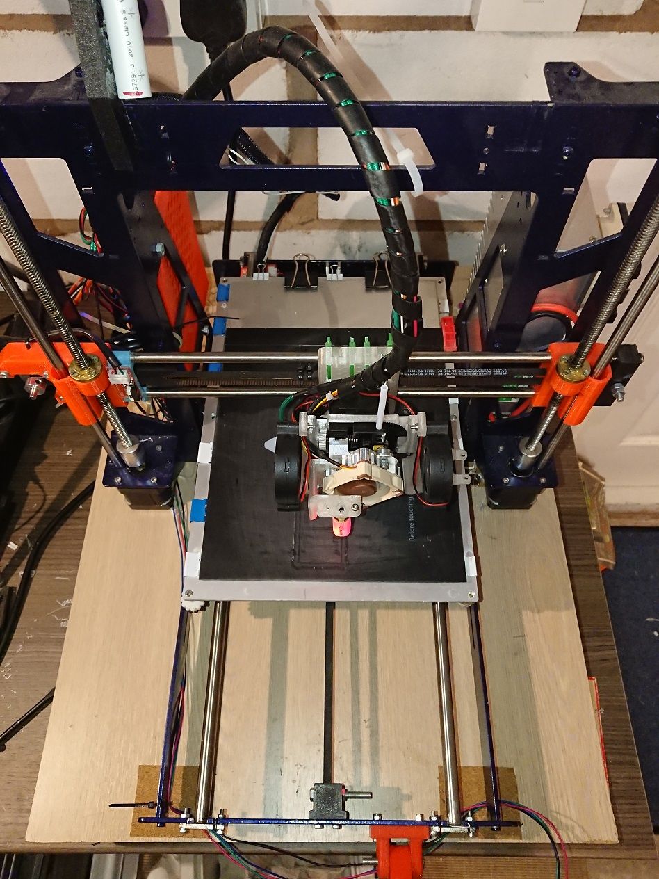
      @droftarts, I'm definitely not winning any lightweight carriage contests 🙂 but I tend to print slow (flexi) so ringing isn't a problem at those speeds.

      Reworked a few of the parts and shaved about 10g off, but that's still not a huge amount, hasn't made much difference but every few -g counts. Further weight reduction is in the pipeline, but more as an experiment with a flex-drive and a 10:1 gear + 3:1 gear on the titan aero (totaling 30:1), no idea if that will work but I'll take a punt for the cost of it. Their standard direct drive replacement kit is 40:1, so its not too far behind, and I'll take a view on backlash once its built.

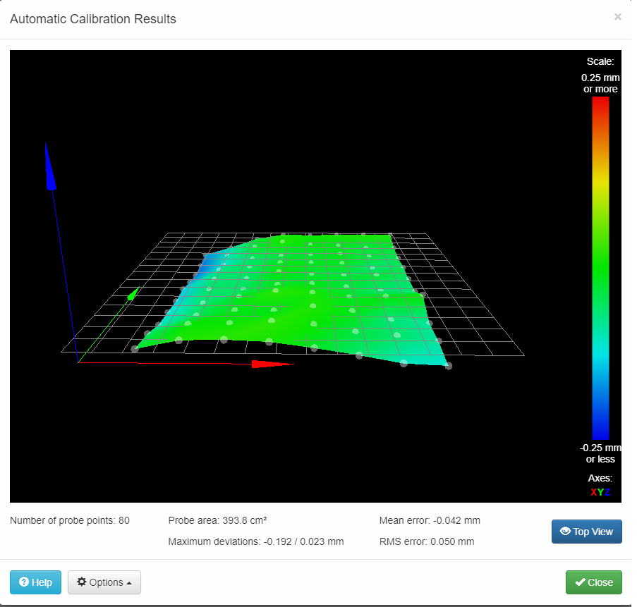
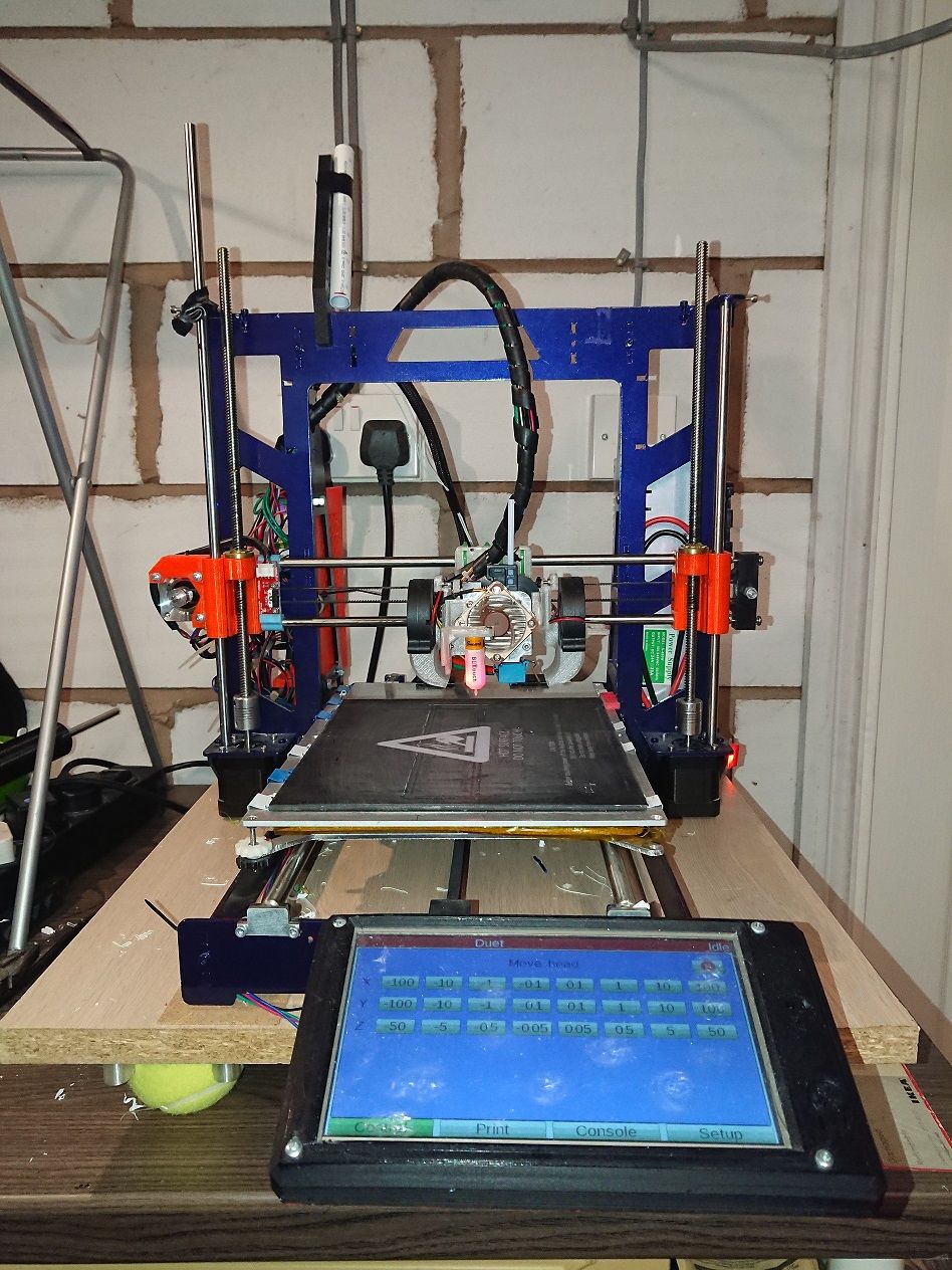
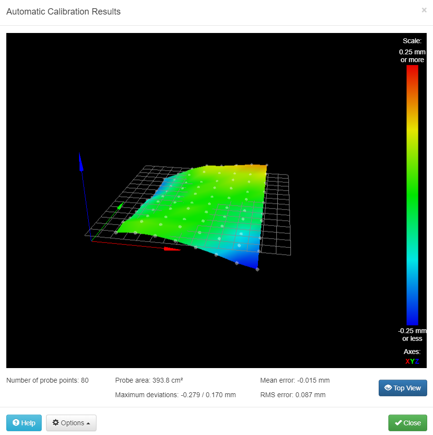
      The deviation, I think...is catered for by the nozzle offset and trigger height (unsure, but it feels like it should?), the probe can access the whole printable area. I think this may be a good time to rework the X-axis with a linear rail + rod setup. That sounds like a better plan than just upping the rods to 10mm from 8mm and adding yet more weight.

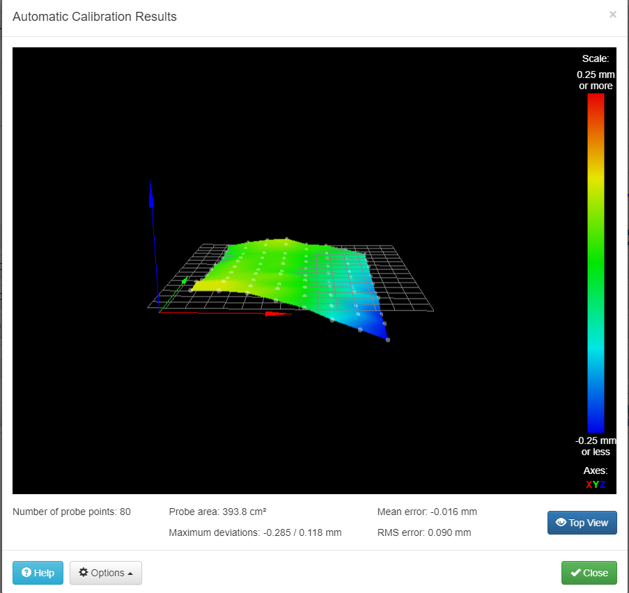
      On further inspection, it looks like the actual y-carriage itself doesn't look quite square/true, 1 of the corners looks not quite straight, so choices...replace with a machined aluminium sheet, or get the carbide tools out and make one out of 3mm CF. The spare 220x220 CF bed I have kicking around was a nice upgrade but so..so..messy to make.

      D

      posted in Tuning and tweaking
      datasquirrelundefined
      datasquirrel
    • RE: Bed leveling/twist

      Measured the rod->wooden base front and back of the right rod, it was out by about -0.15mm on the front. The left rod is out by 0.8 so that will be the next to get adjusted I think.

      Some filing later, and a few layers of foil tape [hack] to raise up the front of the right hand rod, and some minor screw adjustment later, its looking much better:

      bedLevelResults.png

      Still not quite as good as I'd like it, but for a first pass its not too bad. I'll have to draw out a diagram to work out what needs tweaking to adjust what corner as the moment is around the right hand leveling screw.

      Thanks for the help

      D

      posted in Tuning and tweaking
      datasquirrelundefined
      datasquirrel
    • RE: Bed leveling/twist

      @timcurtis67, screw is missing that side as i'm doing 3 point leveling, the screw that side is in the middle of right side of the bed, so to adjust the front right corner up, I'd lower the rear left first.

      I originally tried 4 point, but it caused problems (cant remember what they were when I built it but it was enough to go..hm..no..lets go 3 point)

      posted in Tuning and tweaking
      datasquirrelundefined
      datasquirrel
    • RE: Bed leveling/twist

      Results post 2mm adjustment of surface:
      bedLevelResults.png

      Looking better, going to remove the 2mm packing and re-run just to confirm the change. Certainly interesting...as the surface its mounted on is flat

      D

      posted in Tuning and tweaking
      datasquirrelundefined
      datasquirrel
    • RE: Bed leveling/twist

      Photos as requested, please excuse the mismatched length Z rods...one of those "ill swap it out later.." that never happened.

      DSC_0011.jpg DSC_0010.jpg

      Its been absolutely fine printing (we are well into the 4 figures of hours) so electrically its rock solid, parts dimensions are accurate and square (when its a square), but printing large items, I can see it constantly tweaking the Z height.

      From putting a spirit level across the rods (and then the wooden base) the RH looked to be about 2mm down left to right, identical measurements front of rods to back of rods so I've just slid 2mm worth of board under the LHS under the tennis balls to even it up. Re-running the calibration now.

      D

      posted in Tuning and tweaking
      datasquirrelundefined
      datasquirrel
    • Bed leveling/twist

      Hi All,

      Having some rather entertaining issues with trying to level the bed, looks from the results like a bit of a twist is going on, but cant get my head around trying to fix it, and before i start modifying blindly, figured I'd raise it and see what people think.

      bedLevelResults.png

      The rod end heights are non adjustable, without some filing to release it from its constraints (which...if it needs it, or otherwise, I'm happy to get on and do it), and if additional parts needed to raise it, again I'll fabricate.

      With mesh leveling it prints absolutely fine, but its going to be constantly adjusting height up to the fade height limit which isn't particularly great.

      Any ideas/insight would be greatly appreciated

      D

      Printer details:

      Printer Type: Cartesian, steel frame
      Probe: BLTouch
      Bed: 220x320mm heated aluminium, floating glass top surface
      Y Carriage hardware:4 igus bushes, 10mm rods, 3 point leveling (back left, front left, fixed center right), aluminium mount plate (not particularly strong aluminium at that either)

      Firmware Name: RepRapFirmware for Duet 2 WiFi/Ethernet
      Firmware Electronics: Duet WiFi 1.02 or later
      Firmware Version: 2.02(RTOS) (2018-12-24b1)
      WiFi Server Version: 1.22
      Web Interface Version: 1.22.6

      posted in Tuning and tweaking
      datasquirrelundefined
      datasquirrel
    • RE: Offset positioning

      Thanks both, went back to the drawing board with it and started that section of config again, was pretty close I think but after adjusting the probe homing parameters and ruling everything else out, I discovered 2 things:

      • The probe I had "borrowed" off the other printer had a slightly marginal pin (that was sticking, now cleaned and re-calibrated), it would not give consistent readings between probes.
      • My original measurements were near enough spot on, solved by fixing #1 (and just replacing the probe with the new v2 that arrived with its plastic pin), the other v1 works fine on the other printer but its not as sensitive as the new build.

      Just goes to show check your hardware first and assume nothing, and that each build has its quirks.

      Managed to get the bed levelling working a treat after that, so all good.

      If I get a few minutes I'll put up on the docs a diagram detailing the offsets and whatnot if thats helpful @dc42? The point about HRP is a good one, perhaps its just the weird way I interpreted the docs.

      I also noticed a potential docs/site indexing issue (if not intentional etc), if I stick into google "duet bltouch troubleshooting" the guide linked by @Phaedrux doesnt show up, other docs from dozuki come up on other searches etc.

      Thanks again

      posted in General Discussion
      datasquirrelundefined
      datasquirrel
    • RE: Offset positioning

      Cheers for the clarification, I'll give that a go once this current print has finished, I did something similar but ended up with some weird results that didn't look quite right.

      I think reading the G31 docs here is whats thrown me it off a bit:
      "X and Y offsets of the Z probe relative to the print head (i.e. the position when the empty tool is selected) can be specified. This allows you to calculate your probe coordinates based on the geometry of the bed, without having to correct them for Z probe X and Y offset."

      The print head to me at least means the "unit as a whole" not the nozzle etc (possibly taking it a bit literal), so 0,0 would be the front left of the motor assembly (what would be X=0,Y=0 as it were)

      Its currently running at:
      G31 P25 X-26 Y48.7 Z3 (so looking at it from the front, 26mm left of the nozzle, and 48.7mm towards the back of the printer behind the nozzle), so as long as the +/- looks right there that's pretty close.

      Its predominantly causing some issues with the bed levelling, in terms of "probe cant reach X,Y" but that's I think another question.

      posted in General Discussion
      datasquirrelundefined
      datasquirrel
    • Offset positioning

      Hi All,

      Possibly going a bit mad with this, trying to get offsets all configured etc.

      Coming from a RAMPS/Marlin build, so its been a fun build!

      Printer in question is a newbuild Cartesian, all fresh hardware etc (p3steel build), titan aero, bltouch probe, 200x300 bed. Duet 1.04, 2.01 FW.

      Probe is setup to be used for Z-homing, and that looks all ok (in that it homes and doesn't dive into the bed), actual z-offset needs a bit more work/tuning as it seems to drift.

      So, my query is...X & Y offsets to start:
      -Assuming that X endstop is triggered by the back of the extruder motor, that position there is X=0, the actual nozzle is for the sake of argument 50mm away from that point, so X=50.
      -The probe is from X=0, 25mm away so X=25
      -->This offset here, is that from the X=0 position, or the nozzle position (ie is it 25 or -25)

      Similar sort of question for the Y offset, is it relative to the nozzle or Y=0 position.

      As I am typing this its starting to get a bit clearer possibly, but just need a sanity check please! I suspect I have been sat at my desk just that bit too long before getting around to this and its really not as difficult as I'm making it.

      Thanks!

      posted in General Discussion
      datasquirrelundefined
      datasquirrel