Excelent hopefully when done I'll be happy and upload the step of the negative space needed
AS5601
Ø3MM unknown length
Excelent hopefully when done I'll be happy and upload the step of the negative space needed
AS5601
Ø3MM unknown length
@phaedrux yes, how do I mark as solved?
Cheers for your help
I'm getting extruder 0 reported sensor error.
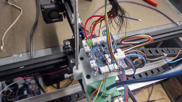
Hi again, I installed a tool board and attached filament sensor, and extruder driver to it.
Not tested filament sensor other than with t with board.
But I think the error is in the config.
It will print for a while then pause
Then fail 2 3 times just after resuming print.
Also new maybe related it won't load the tools unless I emergency stop on start up
Tools are one extruder
And 3 heated beds
Cheers Darrell
@Phaedrux said in Type of wire, duet 3 to toolboard:
it's phone cable for the boards with an actual connector.
https://docs.duet3d.com/en/User_manual/Machine_configuration/CAN_connection
Yes you'd want to ground the metal work as decribed.
Magic that answered what I needed, hopefully the last part till it's reliable
Then to the upgrades 40x40 instead of 20x20
Hi again.
I was going to just cut a network cable and use that to go between the duet and the tool board but wanted to know if their is a better way, Starting to get white elephant vibes on this project. Realsing how much weight I'm putting into the axis movment
also
We recommend connecting the hot end metalwork to ground on the tool board via a resistor (10k to 1M Ohm), if it is not grounded through its mounting system. This will prevent the hot end building up static charge, which might otherwise occur as filament is extruded and may then flash over to the tool board thermistor input, causing damage.
Just means run a wire to the metal plate on the carriage and thrown in a resistor?
Cheers Darrell

 hat
hat
Excelent hopefully when done I'll be happy and upload the step of the negative space needed
AS5601
Ø3MM unknown length
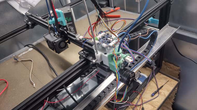
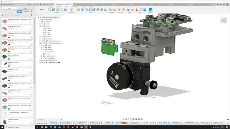
Currently designing a custom mount
I can't work out the distance required between magnet sensor and magnet on hobbed gear
wondering if anyone knows it?
Design shown I forgot about the PCB oops

@phaedrux yes, how do I mark as solved?
Cheers for your help
@phaedrux said in Only able to home one axis.:
wing the endstops triggered or not triggered as they should have been?
Can you confirm axis movement directions are correct?
Managed to update it with Bocca with computer someone left erase jumper in and tried to program it, Verification was intersting .
All axis moving as should be.
m119 showed all not stopped.
then pushed each one and ran m119 to check
X end stop right hand side so when homed = 1000
Y end stop back of machine when pushed = 220
Z end stops top of machine either end of bed when pushed = 0
not sure what "moves the bed and nozzle together." you mean
Z homing works as should as well, with updated G code from your instruction
Video showing some sign of life
https://youtu.be/JRNhOOhQ5pE
Cheers for your help,
Be nice to get it finished now, hopefully get a finished build picture of what might be the longest creality ender 5 pro.
I've got to nip out so will be slow responding
I'm an idiot Will go update and report back

might have just found it. but im confused give me a mo
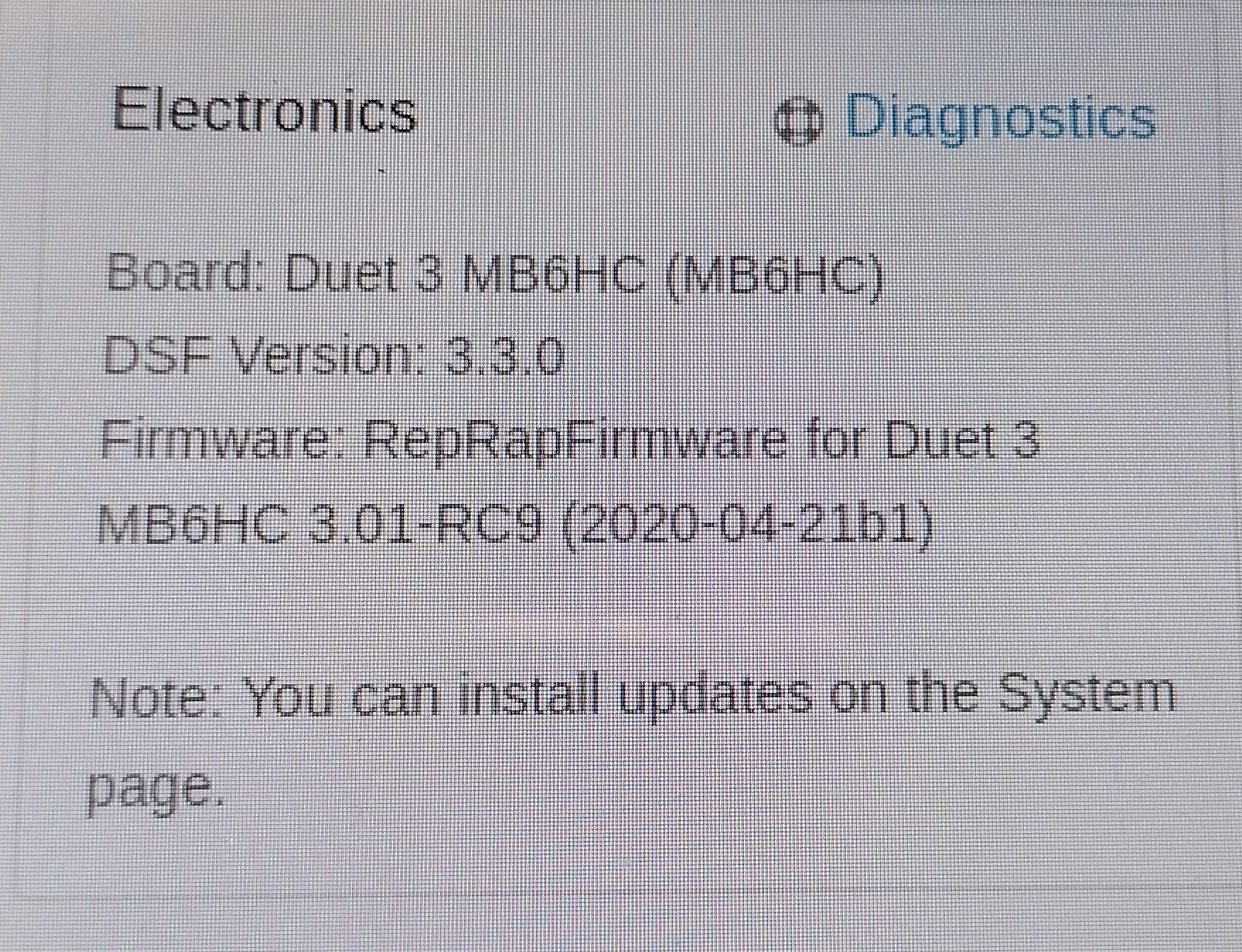
DSF VERSION 3.30
ReRap firmware for duet 3 mb6hc versiom 3.01-rc9 running on duet 3 b1.01 or later
same error occures if I home X then Home X again, Just keeps hitting endstop and restarting homing cycle for selected axis
So X Y Z can all home but only if board is restarted inbetween. If I try to Home X then X fail.--- X then Y fail ect
Seems to just restart the homing file after first home.
Tried changing homing x - y file to as basic as possible
Tried adding a G92 on end
Tried a a fully blind config, direct from configerator and still fails to home, but was still showing 4 heaters on graph so can't have been a full reset of instuction
Ran M119 every axis workign accordingly
implimented the Z changes and Z homes sucessfully, but won't home a second time.
Could it be somthing in the web interface raspberry pi part?
; homex.g
; called to home the X axis
;
; generated by RepRapFirmware Configuration Tool v3.3.10 on Sat Feb 05 2022 17:52:25 GMT+0000 (Greenwich Mean Time)
G91 ; relative positioning
;G1 H2 Z5 F6000 ; LOWER Z relative to current position
G1 H1 X1001 F1800 ; move quickly to X axis endstop and stop there (first pass)
G1 X-5 F6000 ; go back a few mm
;G1 H1 X1005 F360 ; move slowly to X axis endstop once more (second pass)
;G1 H2 Z-5 F6000 ; RAISE Z again
G90 ; absolute positioning
;G92 X0
@phaedrux
Seen cheers, will give it a go tomorrow
Much appreciated.
@phaedrux
home U is the second Z axis, compied and adapted that from
https://duet3d.dozuki.com/Guide/Independent+Z+motors+and+endstop+switches+in+RRF2/18
but shouldn't be in use yet with this problem,
;
; generated by RepRapFirmware Configuration Tool v3.3.10 on Sat Feb 05 2022 17:52:25 GMT+0000 (Greenwich Mean Time)
G91 ; relative positioning
G1 H2 Z5 F6000 ; lift Z relative to current position
M584 Z2 U3 P4 ; split Z motor control to Z and U
; for it to work we have to show U (param P4) in the UI
; Move Z and U down until the switches triggers
G1 H1 Z-305 U-305 F1000
G1 H2 Z5 U5 F1000
G1 H1 Z-305 U-305 F500
; back to combined axes and hidden U
M584 Z2:3 P3
G90 ; Back to absolute positioning
G92 Z0 ; Tell the firmware where we are
; lift Z after probing, without endstop protection
G91
G1 H2 Z10 F1000
G90