Duet3D Logo Duet3D
    • Tags
    • Documentation
    • Order
    • Register
    • Login
    1. Home
    2. JoergS5
    3. Posts
    • Profile
    • Following 0
    • Followers 15
    • Topics 36
    • Posts 2,386
    • Best 294
    • Controversial 0
    • Groups 0

    Posts made by JoergS5

    • RE: Spirograph emulator with Duet2

      @o_lampe said in Spirograph emulator with Duet2:

      Would it be possible to add a rotary tool to a CoreXY frame?

      The current RRF firmware calculates tools as being vertical, non rotating, non moving, describable with fixed XYZ offets (mesh compensation, baby stepping, tool changer depend on this linear offsets, e.g.).

      To avoid this limitations, the tool itself can be divided into a part like a moving/rotating axis and a fixed endpoint which can be dimension zero. With robotic kinematics, you simply add this additional axis to the chain. Forward kinematics is easy to calculate, but inverse kinematics (calculation from world coorinates back to motor positions) can be complicated. It depends on the implementation and axis positions whether it's complicated or not.

      If you design your tool as a spheric design, so that some axes cross in one point with the axes before, the inverse calculation is easier. When you have a prototype and description, we can solve it together.
      posted in CNC
      JoergS5undefined
      JoergS5
    • RE: Kinematics for 5-axis CoreXY printer

      @tcpl this is an interesting design. I will develop the firmware to support it.

      The behaviour of the rotary axes depend on whether they are connected to the starting point (e.g. connected to the bed) or the endpoint (hot end or drill). Connected to one or the other changes the direction of the rotation. I will probably change the definitions and configuration to a general description. I will have to think about how to define it with the M669 parameters easiest.

      posted in MultiAxis Printing
      JoergS5undefined
      JoergS5
    • RE: Kinematics for 5-axis CoreXY printer

      @tcpl are you sure it is AB type? This would mean the rotary axes are parallel to the X and Y axes. I've not seen this type until now, so I only implemented and tested AC and BC. Do you have a picture or drawing to verify the rotary axes types?

      I will continue mid may to develop and can add AB if you need it.

      posted in MultiAxis Printing
      JoergS5undefined
      JoergS5
    • RE: Robotic kinematics

      I'm back with robotics. My partner passed away, I had to mourn, I have a new partner now since a few months, she will be on vacancy alone mid to end may. So this will be the time frame when I will work on robot kinematics again, based on RRF 3.6.

      I will implement an idea I had last year and started implementing some time ago. Robotics solutions are be very different for forward and inverse kinematics. So I thought about a generic approach:

      • a forward chain to combine different drive movements into one movement chain, with one or multiple solutions
      • a backward (inverse) chain with the result of none to multiple solutions
      • forward and backward chains are stored in arrays which can be set by parameters with M669. Kinematic code will simply process the chains
      • to find the chain solutions, the user can think it through mathematically and set the parameters or he can use the to-be-programmed Qt based program to set solutions or simulate them and compare to measurements of the prototype
      • the chain elements are code fragements to implement mathematical solutions. The mathematicsal solutions can be augmented in future releases when necessary

      That's my plan.

      posted in MultiAxis Printing
      JoergS5undefined
      JoergS5
    • RE: 4 axis palletized robot arm (robot kinematics) for 3D printing

      @Nakcam it's all fine with your information, I have "only" a time problem. I can proceed tomorrow for a few hours.

      posted in MultiAxis Printing
      JoergS5undefined
      JoergS5
    • RE: Need help with 5 Bar SCARA configuration

      @DoodleCube said in Need help with 5 Bar SCARA configuration:

      it seems RRF3 on Duet 2 stopped supporting 5 bar

      there are flags in RRF to turn on or off those "exotic" kinematics, so if you're able to compile it yourself, you can turn it on for Duet 2.

      Pins.h
      '# define SUPPORT_FIVEBARSCARA 0
      Set this to 1.

      posted in Firmware installation
      JoergS5undefined
      JoergS5
    • RE: 4 axis palletized robot arm (robot kinematics) for 3D printing

      @Nakcam thank you for clearification.

      Robot kinematics is based on a chain of the actuators: axes with position and orientation and arms between them. The endpoint is just an additional arm without axis. So you can add axes at the beginning and end, but inverse kinematics must be able to calculate it. Your rotating base is included in the 4 axis parallel robot type. Your linear axis at the beginning is something additional. The robot type sometimes has an additional actuator at the endpoint, for rotation of the end plate or for a gripper.

      I proceed tomorrow to develop, because I feel that I have understood it now. I will develop with the blue line being curved optionally. (not a straight line between the three hinges of the blue line).

      posted in MultiAxis Printing
      JoergS5undefined
      JoergS5
    • RE: 4 axis palletized robot arm (robot kinematics) for 3D printing

      @Nakcam sorry for the delay. I had a family problem, I'll try to proceed.

      I want to clearify, please tell me:

      parallelDetail.jpg

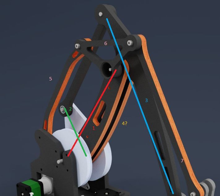
      My understanding is:

      • 1 is the first actuator
      • 2 is the second one. Together they define through the parallelogram the blue arm and the lower end position, lower hinge
      • 4 (the second arm in back of 1) is unclear for me: is it just to stabilize or has it a movement function?
      • 5, 6 and 7 define the upper endpoint in respect to the lower endpoint through parallelism

      Is my understanding correct?

      Comment in advance to the linear rail where you plan to install it on: this fits perfect into a calculation chain, but you have 4 actuators and 3 degrees of freedom (xyz, orientation always the same). This results in indefinite solutions (you can reach a point with different combinations of linear rail and the 3 actuators), i.e. for a desired position there must be installed a strategy. E.g. if the planned coodination is out of reach, move the linear rail to the middle of the new next work area. This movement should not be in a move, but between moves. I want to make something similar: some (5 or 6) robot arm installed on a linear rail at the wall.

      posted in MultiAxis Printing
      JoergS5undefined
      JoergS5
    • RE: Need help with 5 Bar SCARA configuration

      @droftarts said in Need help with 5 Bar SCARA configuration:

      looks like the kinematics expect the X actuator on the left

      the X parameter is for the first and second actuator's X coordinates, Y for the Y. In the documentations example: "E.g. X0:100.5 Y0:0 means 100.5 apart and both on the y axis." makes it clear. But this may be an example of confusing documentation...

      The first actuator should be on the left. Otherwise some details like numbering of the work modes will be wrong.

      @DoodleCube Stepper orientation: the definition is the axes are pointing out from the plane to you and then positive degrees are a rotation counterclockwise. So with H2 single actuator relative movement, a positive rotation must be counterclockwise. e.g. G91 G1 H2 X5 should rotate the first actuator counterlockwise by 5 degrees. Best start with small values and when you have confidence, use a value where you see whether the steps/degrees are correct, e.g. with a 90 degree rotation.

      posted in Firmware installation
      JoergS5undefined
      JoergS5
    • RE: Need help with 5 Bar SCARA configuration

      @oliof said in Need help with 5 Bar SCARA configuration:

      H2/ direct motor moves happen in degrees

      you're right. This may explain my strange experiences.

      posted in Firmware installation
      JoergS5undefined
      JoergS5
    • RE: Need help with 5 Bar SCARA configuration

      @DoodleCube I have some ideas, but I am not sure whether they are correct. But you can try:

      • the wrong read can be due to incorrect steps/degree calculation. Check microsteps and the gear ratio. You can measure the gear ratio by turning one wheel by 360 degree and look how much the other turns. Sometimes documentation says 1:5 and in fact its something like 1:5.18. Another possibility is slightly wrong arm length definition or some tilting of the arms (or Z movement not exactly horizontal arms). Another possibility is that home setting was not exact. The 5 bar Scara is very sensitive to exact degree reading and setting, 0.1 degrees make a big difference. This is different to linear axes, where it doesn't matter much whether the endstop is slightly wrong (with the exception of eg polar kinematics, where the calculation depends on the true absolute position. But cartesian/CoreXY, it can be slightly wrong).
      • when motors are moving in unexpected directions, in most cases it is a wrong stepper direction setting. Just reverse it (M569 S parameter). Your steppers are pointing down, so you need to reverse, compared to the normal usage. When using wrong settings, I also had some very strange behaviour, e.g. different results when using absolute or relative movements. You can verify that absolute and relative movements are behaving correctly both.
      • the M92 settings are steps/degree for rotational axes, I've made a few examples. You can see the controller values of the position by calling M114, they are the values in section Count.

      Hope this helps.

      posted in Firmware installation
      JoergS5undefined
      JoergS5
    • RE: Need help with 5 Bar SCARA configuration

      @DoodleCube said in Need help with 5 Bar SCARA configuration:

      little bit confused on the documentation

      please tell me what you don't understand, then I will clearify it (because I am the one who wrote the documentation - and developed the kinematics).

      Did you read this page? https://docs.duet3d.com/User_manual/Machine_configuration/Configuration_five_bar_parallel_scara

      posted in Firmware installation
      JoergS5undefined
      JoergS5
    • RE: Need help with 5 Bar SCARA configuration

      @DoodleCube

      I guess the C80:200:100:-17 values are wrong. X actuator from 80 to 200 degrees seems ok, but 100 to -17 not. Try 0 to 150 instead. The first value of the second actuator 100 is the min value, so it would mean from 100 to 343 (360 - 17), but I don't think that the code calculates 360-17. It will deny the calculation, because min is higher than the max value. Additionally, the 100 to 343 doesn't include your desired 90 degrees. The homing positions is outside the C values, that's probably the reason for the be unreachable message.

      To make it short, try e.g. C80:200:0:150

      If you want to make it exact, check which areas are reachable by the endpoint with the given mode L2, and watch the possible angles, then set them.

      posted in Firmware installation
      JoergS5undefined
      JoergS5
    • RE: 4 axis palletized robot arm (robot kinematics) for 3D printing

      @Nakcam thanks a lot, I hope this is sufficient information for now to start. After the firmware runs, we can discuss improvements if you like. As always it will depend on what you want to do with it whether it's worth to improve precision etc.

      This remembers me of that I need a load lifter, maybe I'll build it this this kinematics. Similar to a IRB 760.

      posted in MultiAxis Printing
      JoergS5undefined
      JoergS5
    • RE: 4 axis palletized robot arm (robot kinematics) for 3D printing

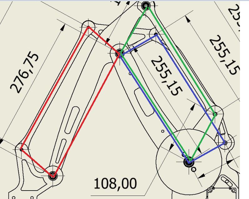
      @Nakcam here is a short explanation of the parallelograms:

      parall.jpg

      The blue and red ones are connected through the triangle. The triangle is like a curve of the arms from up to down.

      The opposite sides of blue, red and green parallelograms shall be parallel each. When they become "flat", i.e. small angles and opposite sides near at each other, the movements and caluclations will become inexact. So this situations should be avoided.

      posted in MultiAxis Printing
      JoergS5undefined
      JoergS5
    • RE: 4 axis palletized robot arm (robot kinematics) for 3D printing

      @Nakcam thank you! I don't have Fusion, so from your image I can make a prototype as well.

      Please measure the triangle lenghts as well, from hinge to hinge each.

      posted in MultiAxis Printing
      JoergS5undefined
      JoergS5
    • RE: 4 axis palletized robot arm (robot kinematics) for 3D printing

      @Nakcam the D values make only sense when the axes are calculated in the chain. This is only implemented for CoreXY. I you want to test setting D values in advance, just define your config for CoreXY.

      posted in MultiAxis Printing
      JoergS5undefined
      JoergS5
    • RE: 4 axis palletized robot arm (robot kinematics) for 3D printing

      @Nakcam I can work next weekend on it, and it would be nice if you can make some tests with the prototype, verifiying code, while I develop the code. I can provide you the RRF binary for each test.

      posted in MultiAxis Printing
      JoergS5undefined
      JoergS5
    • RE: 4 axis palletized robot arm (robot kinematics) for 3D printing

      @Nakcam the kinematics is not implemented yet, but I'll try to do it with your help.

      4parParts.png

      Please confirm or correct me:

      • 1 is connected with first actuator/stpper
      • 2 is connected with the other
      • 3 is connected to base
      • 4 is a hinge connecting three parts: tringle low, big arm and other big arm

      Your short video looks like the front horizontal platform tilts a bit, the front going a bit down. This may be an optical illustion. But if it's real, then some of the angles are wrong and the construction is not a parallelogram. Maybe you'll need to change the prototype a bit. But let's make the kinematics first.

      BTW I like your prototype, because the gear is belt based, which means low or no backlash. The planetary based gears have some play when changing orientation of the rotations.

      posted in MultiAxis Printing
      JoergS5undefined
      JoergS5
    • RE: 4 axis palletized robot arm (robot kinematics) for 3D printing

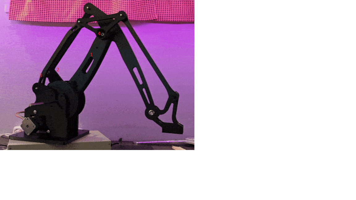
      @Nakcam it's more complicated then serial Scara:

      the platform in front stays horizontal, due to the arm's nature: they make movements of a parallelogram, which means some of the arms stay parallel. The calculation is simliar to 5 bar paralleld scara, where two actuators together make a movement which is restricted by the connection at the end point. The inverse kinematics must calculate back with this restriction, with the added problem that there are multiple solutions for the inverse kinematics.

      Your image looks fine, but differs from the black robot model: the back arms of his model are fix connected to the platform at the bottom. (looking from back, the left one)

      4parallel_fixedarm_small2.jpg

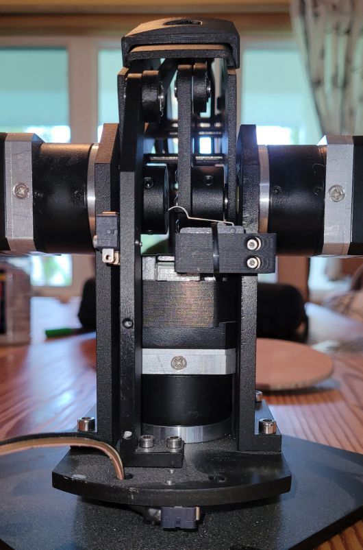
      Do you have a prototype, or only the drawing? If you have a working model or prototype, please give me information about how it is built exactly. (which of the arms are connected to the actuators=steppers, which are only connected through hinge, but not driven by the stepper)

      posted in MultiAxis Printing
      JoergS5undefined
      JoergS5