Duet3D Logo Duet3D
    • Tags
    • Documentation
    • Order
    • Register
    • Login
    1. Home
    2. kcress
    3. Posts
    • Profile
    • Following 0
    • Followers 1
    • Topics 6
    • Posts 37
    • Best 5
    • Controversial 0
    • Groups 0

    Posts made by kcress

    • RE: Mesh Confusion

      Well no one could tell me how to just drive a specific stepper output...

      So, I decided to simply de-allocate three of the Z motors at a time in the M584 line of the config.g and do a Z move of the remaining one after an M564 H0 to allow un-homed movements. SMALL moves!

      Doing that I could see which of the 4 Z motors was actually moving as compared to which one I thought should be moving.

      Turned out instead of:

      ; --- drive map ---
      ;    _______
      ;   | 3 | 4 |
      ;   | ----- |
      ;   | 2 | 5 |
      ;    -------
      ;     FRONT
      

      I actually had:

      ; --- drive map ---
      ;    _______
      ;   | 5 | 4 |
      ;   | ----- |
      ;   | 2 | 3 |
      ;    -------
      ;     FRONT
      

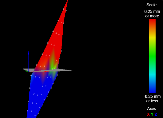
      Which utterly screwed up everything causing the incrementing LR corner error and decrementing RF corner error with each G32 command. The errors even accelerated as with each subsequent G32 the error was greater demanding greater yet miscorrections

      I'd traced all the cables manually but accidentally swapped those two even writing which Z motor they were(n't) on the cables.

      I swapped those two on the 6HC and then ran HOME ALL and then consecutive G32s.

      12/28/2021, 3:06:34 AM G32
      Leadscrew adjustments made: -0.757 -0.154 1.087 -1.036, points used 4, (mean, deviation) before (0.024, 0.619) after (-0.000, 0.000)

      12/28/2021, 3:07:28 AM G32
      Leadscrew adjustments made: 0.099 0.146 0.462 0.296, points used 4, (mean, deviation) before (0.286, 0.104) after (-0.000, 0.000)

      12/28/2021, 3:08:30 AM G32
      Leadscrew adjustments made: 0.015 0.026 0.055 0.039, points used 4, (mean, deviation) before (0.038, 0.011) after (-0.000, 0.000)

      12/28/2021, 3:21:13 AM G32
      Leadscrew adjustments made: 0.007 0.005 0.006 0.006, points used 4, (mean, deviation) before (0.006, 0.001) after (0.000, 0.000)

      Dang, what a struggle that was.
      I do like the results! I appreciate only 0.0003" errors!!

      So the lesson with 4 Z motors is this:

      If, with repeated G32 (bed.g) runs any one corner increases its error positively while any other corner simultaneously has an increasingly negative error electrically swap those two corner's Z motors.

      posted in Tuning and tweaking
      kcressundefined
      kcress
    • RE: Mesh Confusion

      @engikeneer Hi!
      That's right the S now has to equal the number of Z motors. Thanks for reminding me.

      As I mentioned the MACRO I whipped up? That's the G30 with S-1. Works well!

      posted in Tuning and tweaking
      kcressundefined
      kcress
    • RE: Mesh Confusion

      @Robert: Yes tried your order. No obvious change.
      Tried several different orders all with worse, even E-Stop pounding worse.

      @engikeneer: Have not tries S3 since my bed is 3/8" plate aluminum. Only the gantry is Z on all four corners.

      Also this makes me hesitate:
      NOTE: From RepRapFirmware version 1.09 to 3.01-RC4, the number of factors may be 3, 4 or 5 when doing old-style auto bed compensation on a Cartesian or CoreXY printer. This form of bed compensation has been removed in RRF 3.01-RC5 and later.

      @phaedrux To be clear, the values in M671 are supposed to be the physical mm locations of the actual gantry posts regardless of the head's ability to never make it to those points right?

      Please check me here. Given the Z drives are 2,3,4,5 exactly as depicted in the square below. And, are in numeric order. Front LEFT is (0,0) Isn't my M671 correct?

      M671 X-60.0:-60.0:460:460 Y-30.0:470.0:470.0:-30.0 S20   ; Z belts at 4 corners where the slides are
      ; --- drive map ---
      ;    _______
      ;   | 3 | 4 |
      ;   | ----- |
      ;   | 2 | 5 |
      ;    -------
      ;     FRONT
      

      How can I drive the z motors independently of everything else to test their channel # and positions?

      I made a MACRO to probe the 4 corners and only report the 4 values. The numbers repeat within a few 0.001mm.

      posted in Tuning and tweaking
      kcressundefined
      kcress
    • RE: Mesh Confusion

      @rjenkinsgb Robert!! You're correct. That example is crazy. Using LR then RR the Fcenter while having defined them in LR/FC/RR order.

      I agree it seems like there is a mismatch on my machine as each time the correction gets worse with the LR tower. Unhelpfully not much guidance anywhere on how to figure out which two are backwards.

      Clearly my LR is goes haywire fast. The next worst I guess is my FR. But what does this mean? That the LR and FR are backwards or the LF and RR? Ugh.

      I swapped 3 and 5 (LR and RF). The error between subsequent passes grew on the the LR and RF values.
      LR pass 1 1.023
      LR pass 2 2.233

      RF pass 1 -1.214
      RF pass 2 -2.210

      Instead swapped LF with RR.
      Very bad.

      Then instead swapped LR with LF....
      The LR stepper started doing something odd. Either losing steps or adding steps. It aborted with a "too large error", (more than 5mm).

      posted in Tuning and tweaking
      kcressundefined
      kcress
    • RE: Mesh Confusion

      @phaedrux Hi.
      I corrected the M584 - M669 precedence issue : No obvious change.

      I also put the mapping of the 4 Z motors into the same M584 statement to bury any smoking gun.

      M584 X0.0 Y0.1 Z0.2:0.3:0.4:0.5 E1.1         ; set drive mapping (combining all assignments in one line)
      

      Also no change.

      I had the entire heavy printer propped up at an angle and thought maybe that was causing some frame torque issue. I dropped it down level and closed up everything.

      No change.

      I then ran G32 which runs in turn runs bed.g which looks like this:

      M561                         ; clears any bed transform
      
      G30 P0 X20 Y20 Z-99999       ; probe (-99999) near a leadscrew X0,Y0
      G30 P1 X20 Y380 Z-99999      ; probe near a leadscrew X0,Y400
      G30 P2 X380 Y380 Z-99999     ; probe near a leadscrew X400,Y400
      G30 P3 X380 Y20 Z-99999 S4   ; probe near a leadscrew X400,Y0 and calibrate 4 Z axis motors (Tram them)
      

      Pretty sure the drives are in the same order of points used in M671.

      I've then run G32 multiple times right after each other.

      Recall my 4 Z motors are ordered this way:

      ; --- drive map ---
      ;    _______
      ;   | 3 | 4 |
      ;   | ----- |
      ;   | 2 | 5 |
      ;    -------
      ;     front
      

      Here's what three tests in a row look like!
      The third faulted refusing to do a tram calculation because the error exceeded my 5mm limit. (Whole sequence has been repeated several times with a fault eventually after 3 or 4 trammings.)

      ;          --- drive map ---
                        BACK
      ;          -----------------
      ; pass 1  | -2.429 | -0.012 |
      ; pass 2  | -4.943 |  0.010 |
      ; pass 3  | -7.348 |  0.019 |
      ;         | ------ | ------ |
      ; pass 1  |  0.038 |  2.486 |
      ; pass 2  |  0.531 |  2.427 |
      ; pass 3  |  0.387 |  0.268 |
      ;          -----------------
      ;                FRONT
      

      I'm going crazy here after days of these results.

      Any Ideas?

      posted in Tuning and tweaking
      kcressundefined
      kcress
    • RE: Mesh Confusion

      @phaedrux Hi Phaedrux. Thanks for the assist.

      BLTouch is the z-probe.

      config.g

      ; Configuration file for Duet 3 (firmware version 3.3)
      ; executed by the firmware on start-up
      ;
      
      ; General preferences
      G90                                          ; send absolute coordinates...
      M83                                          ; ...but relative extruder moves
      M550 P"Troodon"                              ; set printer name
      M669 K1                                      ; select CoreXY mode
      
      ; Wait a moment for the CAN expansion boards to start
      G4 S2
      
      ; Network
      M552 P0.0.0.0 S1                             ; enable network and acquire dynamic address via DHCP
      M586 P0 S1                                   ; enable HTTP
      M586 P1 S0                                   ; disable FTP
      M586 P2 S0                                   ; disable Telnet
      
      ; Drives
      M569 P0.0 S0                                 ; physical drive 0.0 goes BACKwards
      M569 P0.1 S0                                 ; physical drive 0.1 goes BACKwards
      M569 P0.2 S0                                 ; physical drive 0.2 goes BACKwards
      M569 P0.3 S1                                 ; physical drive 0.3 goes forwards
      M569 P0.4 S0                                 ; physical drive 0.4 goes BACKwards
      M569 P0.5 S1                                 ; physical drive 0.5 goes forwards
      M569 P1.1 S0                                 ; physical drive 1.0 goes BACKards
      M584 X0.0 Y0.1 Z0.2 E1.1                     ; set drive mapping
      M350 X16 Y16 Z16 E16 I1                      ; configure microstepping with interpolation
      M92 X80.00 Y80.00 Z400.00 E727.00            ; set steps per mm
      M566 X2000 Y2000 Z602.65 E250                ; set maximum instantaneous speed changes (mm/min)
      M203 X20000 Y20000 Z1500 E3200               ; set maximum speeds (mm/min)
      M201 X1500 Y1500 Z500 E3200                  ; set accelerations (mm/s^2)
      M906 X1200 Y1200 Z1200 E420 I60              ; set motor currents (mA) and motor idle factor in per cent
      M84 S60                                      ; Set idle timeout
      
      ; Multiple Z motors
      M584 Z0.2:0.3:0.4:0.5                        ; assigning all the Z drives
      
      ; Axis Limits
      M208 X0 Y0 Z-5 S1                            ; set axis minima
      M208 X400 Y400 Z480 S0                       ; set axis maxima
      
      ; Endstops
      M574 X2 S1 P"io1.in"                         ; configure switch-type (e.g. microswitch) endstop for high end on X via pin io1.in
      M574 Y2 S1 P"io2.in"                         ; configure switch-type (e.g. microswitch) endstop for high end on Y via pin io2.in
      
      ; Z-Probe
      M574 Z0 P"nil"                               ; no Z endstop switch, free up Z endstop input
      M558 P9 C"io5.in" H10 R1 F300 T6000 A5 S0.02 ; BLTouch connected to Z probe IN pin
      M950 S5 C"io5.out"                           ; BLTouch connected to Z probe OUT pin that the PWM should spew from
      M574 Z1 S2                                   ; Set endstops controlled by probe
      
      G31 P50 X-2 Y22 Z1.13                        ; Set Z probe trigger value, offset and trigger height (Is now Z1.13)
      M557 X10:410 Y21:400 S49                     ; define mesh grid
      
      ; --- z-axis stepper leveling configuration ---
      ;M671 X-100:-100:420:420 Y380:-115:-115:380 S5     ; Z belts at 4 corners Formbot's numbers ??!??
      M671 X-60.0:-60.0:460:460 Y-30.0:470.0:470.0:-30.0 S5   ; Z belts at 4 corners where the sliders are
      
      ; --- drive map ---
      ;    _______
      ;   | 3 | 4 |
      ;   | ----- |
      ;   | 2 | 5 |
      ;    -------
      ;     front
      
      ; Heaters
      M308 S0 P"temp0" Y"thermistor" T100000 B4138 C0 ;R4700  ; define bed temperature sensor
      M308 S1 P"temp1" Y"thermistor" T100000 B4138 C0 ;R4700  ; define E0 temperature sensor
      M950 H0 C"out0" T0                           ; heater 0 uses the bed_heat pin, sensor 0
      M950 H1 C"out1" T1                           ; heater 1 uses the e0_heat pin and sensor 1
      M307 H0 B0 R0.296 C925.8 D1.43 S1.00 V23.9   ; M303 PID Auto Tuning of the Bed heater
      M307 H1 B0 R2.493 C242.1 D10.67 S1.00 V23.9  ; M303 PID Auto Tuning of the Extruder heater
      M140 H0                                      ; map heated bed to heater 0
      M143 H0 S120                                 ; set temperature limit for heater 0 (Bed) to 120C
      M143 H1 S280                                 ; set temperature limit for heater 1 (Extruder) to 280C
       
      
      ; Fans
      M950 F0 C"out4" Q500                         ; create fan 0 on pin out4 and set its frequency
      M106 P0 S0 H-1                               ; set fan 0 value. Thermostatic control is turned off
      M950 F1 C"out9" Q500                         ; create fan 1 on pin out9 and set its frequency
      M106 P1 S1 H1 T45                            ; set fan 1 value. Thermostatic control is turned on
      M950 F2 C"out5" Q500                         ; create fan 2 on pin out5 and set its frequency (TEMPORARILY ZERO)
      M106 P2 S1 H-1                               ; set fan 2 value. Thermostatic control is turned off
      M950 F3 C"out7" Q500                         ; create fan 3 on pin out7 and set its frequency (TEMPORARILY ZERO)
      M106 P3 S1 H-1                               ; set fan 3 value. Thermostatic control is turned off
      M950 F4 C"out8" Q500                         ; create fan 4 on pin out8 and set its frequency
      M106 P4 S1 H-1                               ; set fan 4 value. Thermostatic control is turned off
      
      ; Tools
      ;M563 P0 D0 F-1                               ; define tool 0
      M563 P0 D0 H1 F1                             ; define tool 0
      G10 P0 X0 Y0 Z0                              ; set tool 0 axis offsets
      G10 P0 R0 S0                                 ; set initial tool 0 active and standby temperatures to 0C
      
      ; ---filament sensing---
      ;M591 D0 P1 C"io_3" S1                        ; extruder 0, simple sensor signal high filament present, pin connected to, enable when printing from SD
      
      ; --- firmware retraction ---                ; Apparantly not used?
      ;M207 S2.5 R0 F6500 T4500 Z0	             ; [ Snnn positive length to retract, in mm ]
      					                         ; [ Rnnn positive or negative additional length to un-retract, in mm ]
      					                         ; [ Fnnn retraction feedrate, in mm/min ]
      					                         ; [ Tnnn feedrate for un-retraction if different from retraction, mm/min ]
      					                         ; [ Znnn additional zlift/hop ]
      
      
      ; ---LED Color Driving---
      M950 F6 C"1.out6" Q500                       ; create fan 6 on pin out6 and set its frequency !!LED COLOR!!
      M106 P6 S1 H-1                               ; set fan 6 value. Thermostatic control is turned off !!LED COLOR!!
      M950 F7 C"1.out7" Q500                       ; create fan 7 on pin out7 and set its frequency !!LED COLOR!!
      M106 P7 S1 H-1                               ; set fan 7 value. Thermostatic control is turned off !!LED COLOR!!
      M950 F8 C"1.out8" Q500                       ; create fan 8 on pin out8 and set its frequency !!LED COLOR!!
      M106 P8 S1 H-1                               ; set fan 8 value. Thermostatic control is turned off !!LED COLOR!!
      
      M106 P4 S000								; TEMP STOP DRIVER FAN
      M106 P3 S000								; TEMP STOP PAN FAN
      M106 P2 S000								; TEMP STOP HEPA FAN
      

      homeall.g (which is all the individual axis repeated)

      ; homeall.g
      ; I've edited this to be the three indiviual homes in classic order
      ; If anything is changed here check the individual axii
      ;
      ;
      ; homex.g
      ; called to home the X axis
      ; anything changed here needs to also be done in homeall.g
      ;
      G91              ; relative positioning
      G1 H2 Z5 F6000   ; lift Z relative to current position
      G1 H1 X400 F1800 ; move quickly to X axis endstop and stop there (first pass)
      G1 X-5 F6000     ; go back a few mm
      G1 H1 X400 F360  ; move slowly to X axis endstop once more (second pass)
      G1 H2 Z-5 F6000  ; lower Z again
      G90              ; absolute positioning
      
      ; homey.g
      ; called to home the Y axis
      ; anything changed here needs to also be done in homeall.g
      ;
      G90              ; absolute positioning
      G1 X200 F6000    ; get the X axis away from the X axis high limit to give the drag chain room to not compression bind on Y move.
      G91              ; relative positioning
      G1 H2 Z5 F6000   ; lift Z relative to current position
      G1 H1 Y400 F1800 ; move quickly to Y axis endstop and stop there (first pass)
      G1 Y-5 F6000     ; go back a few mm
      G1 H1 Y400 F360  ; move slowly to Y axis endstop once more (second pass)
      ;G1 H2 Z-5 F6000  ; (*** removed from homeall.g as it causes a pointless curtsy) lower Z again
      G90              ; absolute positioning
      
      ; homez.g
      ; called to home the Z axis
      ; anything changed here needs to also be done in homeall.g
      ;
      G91                ; relative positioning
      ;G1 H2 Z5 F6000     ; (*** removed from homeall.g as it causes a pointless curtsy) lift Z relative to current position
      G90                ; absolute positioning
      G1 X200 F6000      ; center X position on build platform
      G1 Y200 F6000      ; center Y position on build platform
      G91                ; relative positioning
      ;G1 H1 Z-205 F1800 ; move Z down until the endstop is triggered
      G30                ; Do a single probe to home our Z axis
      G90                ; Make sure we are in absolute mode
      G1 Z10 F6000       ; Rapidly move the Z axis to Z=10.
      

      bed.g

      ; bed.g
      ; called to perform automatic bed compensation via G32
      
      ; Note: G28 Homes ALL axises
      ; Note: G29 Does a billion probes for mapping a bed mesh compensation.  A M561 to wipe priors should be done before G29 
      ; Note: G32 Does a Z axis tramming only via directly invoking the macro "bed.g"
      
      
      ;M561 ; clears any bed transform
      ;G29  ; probe the bed and enable compensation
      
      
      G28 ; home
      G30 P0 X20 Y20 Z-99999       ; probe near a leadscrew
      G30 P1 X20 Y380 Z-99999      ; probe near a leadscrew
      G30 P2 X380 Y380 Z-99999     ; probe near a leadscrew
      G30 P3 X380 Y20 Z-99999 S4   ; probe near a leadscrew and calibrate 4 motors
      

      No mesh.g

      posted in Tuning and tweaking
      kcressundefined
      kcress
    • Mesh Confusion

      ice_screenshot_20211220-212904.png

      Lots of users seem to be struggling with this at the moment. None of the other threads have worked for me.

      I'm struggling to see how I can get a heightmap like this.

      This is Troodon 400 with 4 z-axis motors. I can knock it way out of skew and run the bed.g on it an watch it measure all four corners then watch as the entire gantry jerks into being perpendicular with the bed.

      I Home All.
      Then Tram with G32.
      Then Home All again, Z dead center.
      Then run G29 S0 for the bed mesh.

      You see the height map that's generated. It's a fairly flat plane, seemingly what tramming should've resolved. Shouldn't it have?

      RepRapFirmware height map file v2 generated at 2021-12-20 21:27, min error -4.036, max error 3.824, mean -0.418, deviation 1.898
      axis0,axis1,min0,max0,min1,max1,radius,spacing0,spacing1,num0,num1
      X,Y,10.00,410.00,21.00,400.00,-1.00,49.00,49.00,9,8
            0,      0,      0,      0,      0,      0,      0,      0,      0
       -0.197,  0.308,  0.836,  1.400,  1.999,  2.574,  3.185,  3.824,      0
       -0.869, -0.310,  0.228,  0.798,  1.380,  1.971,  2.569,  3.215,      0
       -1.620, -1.240, -0.400,  0.215,  0.781,  1.361,  1.969,  2.622,      0
       -2.196, -1.804, -1.392, -0.925, -0.441,  0.036,  0.533,  1.067,      0
       -2.795, -2.356, -1.935, -1.451, -0.956, -0.452,  0.069,  0.628,      0
       -3.492, -3.130, -2.741, -2.291, -1.842, -1.389, -0.896, -0.381,      0
       -4.036, -3.637, -3.213, -2.740, -2.240, -1.735, -1.219, -0.651,      0
      
      posted in Tuning and tweaking
      kcressundefined
      kcress
    • RE: 3HC Extruder missing in action

      @dc42 More learning. Thanks!

      posted in Using Duet Controllers
      kcressundefined
      kcress
    • RE: 3HC Extruder missing in action

      @deckingman

      1. Check.

      2. Tried M302 P1 four times. It may have allowed the extruder to run on the 6HC but I'm thinking the DWC may have still been blocking the sending of any extrude or retraction presses while it looked only at the temperature before enabling the sowtware buttons. e.g. if I'd have sent the extrude G code it probably would've extruded.

      3. Totally get this but because this new extruder has never seen filament and I was in commissioning mode I never even thought about heat at all.

      4. Thanks for clearing this up. Makes sense.
        The default temp allowing extrusion is 160C while the default temp allowing retraction is 90C.

      Thanks again. This bought me a night of sleep. 🙂

      Count this one solved.

      posted in Using Duet Controllers
      kcressundefined
      kcress
    • RE: 3HC Extruder missing in action

      @deckingman Looks like this:

      ice_screenshot_20211202-052017.png

      Can't extrude or retract.

      Do I see the extruder drive?

      Why yes! Yes I do.

      ice_screenshot_20211202-052356.png

      "under extrusion control, do you see "E0" listed?"

      Why no! No I don't. 😕
      See above picture. Just states Extrusion Control nothing about a particular extruder. I take it maybe it should?

      M302!! Okay. M302 P1 seems to make no difference. Dang.

      However! M302 S120 R110 then heating the extruder up to 160C (but only in active mode not standby)
      Lights up the Retract and Extrude and they now work.

      Thanks much deckingman, that's entirely what I was missing. No wonder I couldn't find anything about it.

      posted in Using Duet Controllers
      kcressundefined
      kcress
    • RE: 3HC Extruder missing in action

      @joergs5 I was just going to ask how to tell if the 3HC was thinking and was there an M122 for extra boards. You must be clairvoyant.

      Seems to be there..

      Elsewhere I listed my drives so I thought they were sort of approved selections but maybe not. I list them below again.

      M122 B1
      Diagnostics for board 1:
      Duet EXP3HC firmware version 3.3 (2021-06-15 16:12:41)
      Bootloader ID: SAME5x bootloader version 2.3 (2021-01-26b1)
      Never used RAM 159104, free system stack 4378 words
      Tasks: Move(notifyWait,0.0%,160) HEAT(delaying,0.1%,104) CanAsync(notifyWait,0.0%,69) CanRecv(notifyWait,0.0%,82) CanClock(notifyWait,0.0%,71) TMC(notifyWait,44.8%,63) MAIN(running,46.9%,438) IDLE(ready,0.0%,39) AIN(delaying,8.2%,263), total 100.0%
      Last reset 05:40:57 ago, cause: software
      Last software reset data not available
      Driver 0: position 0, 420.0 steps/mm,  standstill, reads 62464, writes 16 timeouts 0, SG min/max 0/0, steps req 0 done 0
      Driver 1: position 0, 80.0 steps/mm,  standstill, reads 62470, writes 11 timeouts 0, SG min/max 0/0, steps req 0 done 0
      Driver 2: position 0, 80.0 steps/mm,  standstill, reads 62470, writes 11 timeouts 0, SG min/max 0/0, steps req 0 done 0
      Moves scheduled 0, completed 0, in progress 0, hiccups 0, step errors 0, maxPrep 0, maxOverdue 0, maxInc 0, mcErrs 0, gcmErrs 0
      Peak sync jitter -7/7, peak Rx sync delay 182, resyncs 0/0, no step interrupt scheduled
      VIN: 24.3V, V12: 12.2V
      MCU temperature: min 32.6C, current 33.2C, max 33.9C
      Ticks since heat task active 124, ADC conversions started 20457198, completed 20457197, timed out 0, errs 0
      Last sensors broadcast 0x00000000 found 0 129 ticks ago, loop time 0
      CAN messages queued 30, send timeouts 0, received 184124, lost 0, free buffers 37, min 37, error reg 0
      dup 0, oos 0/0/0/0, bm 0, wbm 0, rxMotionDelay 0
      

      6HC:
      Drive 0 => X (P0.0)
      Drive 1 => Y (P0.1)
      Drive 2 => Z1 (P0.2)
      Drive 3 => Z2 (P0.3)
      Drive 4 => Z3 (P0.4)
      Drive 5 => Z4 (P0.5)

      3HC:
      Drive 0 => E0 (P1.0)

      posted in Using Duet Controllers
      kcressundefined
      kcress
    • RE: 3HC Extruder missing in action

      @joergs5 Thanks.

      Trying to get my head around why that would cause the extruder to not show up at all. I could see the filament-out sensor not working correctly.

      I commented out the existence of the filament-out sensor (M591) with no improvement.

      posted in Using Duet Controllers
      kcressundefined
      kcress
    • 3HC Extruder missing in action

      Hi,

      Bringing up my re-controlled Vivendo Troodon 400 with a 6HC and 3HC.

      I have almost everything working:
      Temp sensors
      All the axis drives including 4-Z steppers.
      5 fans 🙇
      I have it doing all zeroing and even bed tramming! Awesome to see it tram a skewed-up gantry. 🙂

      One of the last things I just turned to is the Extruder but I now notice it's grayed out on the DWC.. Bummer.

      The extruder is the only thing on the 3HC. I M584'd it in the config file first thing.

      The red lights blink in rigid synchronicity. Lots of lights on on the 3HC.

      I don't have any particular idea of where to start to fix this.
      Suggestions welcome.

      DWC version: Duet Web Control 3.3.0
      RepRapFirmware for Duet 3: MB6HC 3.3 (2021-06-15)

      Here's the config.g

      ; Configuration file for Duet 3 (firmware version 3.3)
      ; executed by the firmware on start-up
      ;
      ; 
      
      ; General preferences
      G90                                          ; send absolute coordinates...
      M83                                          ; ...but relative extruder moves
      M550 P"Troodon"                              ; set printer name
      M669 K1                                      ; select CoreXY mode
      
      ; Wait a moment for the CAN expansion boards to start
      G4 S2
      
      ; Network
      M552 P0.0.0.0 S1                             ; enable network and acquire dynamic address via DHCP
      M586 P0 S1                                   ; enable HTTP
      M586 P1 S0                                   ; disable FTP
      M586 P2 S0                                   ; disable Telnet
      
      ; Drives
      M569 P0.0 S0                                 ; physical drive 0.0 goes BACKwards
      M569 P0.1 S0                                 ; physical drive 0.1 goes BACKwards
      M569 P0.2 S0                                 ; physical drive 0.2 goes BACKwards
      M569 P0.3 S1                                 ; physical drive 0.3 goes forwards
      M569 P0.4 S0                                 ; physical drive 0.4 goes BACKwards
      M569 P0.5 S1                                 ; physical drive 0.5 goes forwards
      M569 P1.0 S1                                 ; physical drive 1.0 goes forwards
      M584 X0.0 Y0.1 Z0.2 E1.0                     ; set drive mapping
      M350 X16 Y16 Z16 E16 I1                      ; configure microstepping with interpolation
      M92 X80.00 Y80.00 Z400.00 E420.00            ; set steps per mm
      M566 X2000 Y2000 Z603 E1000                  ; set maximum instantaneous speed changes (mm/min)
      M203 X20000 Y20000 Z1500 E10000              ; set maximum speeds (mm/min)
      M201 X1500 Y1500 Z500 E10000                 ; set accelerations (mm/s^2)
      M906 X1400 Y1400 Z1400 E1300 I50             ; set motor currents (mA) and motor idle factor in per cent
      M84 S30                                      ; Set idle timeout
      
      ; Multiple Z motors
      M584 Z0.2:0.3:0.4:0.5                        ; assigning all the Z drives
      
      ; Axis Limits
      M208 X0 Y0 Z-5 S1                            ; set axis minima
      M208 X400 Y400 Z480 S0                       ; set axis maxima
      
      ; Endstops
      M574 X2 S1 P"io1.in"                         ; configure switch-type (e.g. microswitch) endstop for high end on X via pin io1.in
      M574 Y2 S1 P"io2.in"                         ; configure switch-type (e.g. microswitch) endstop for high end on Y via pin io2.in
      
      ; Z-Probe
      M574 Z0 P"nil"                               ; no Z endstop switch, free up Z endstop input
      M558 P9 C"io5.in" H10 R1 F300 T6000 A5 S0.02 ; BLTouch connected to Z probe IN pin
      M950 S5 C"io5.out"                           ; BLTouch connected to Z probe OUT pin that the PWM should spew from
      M574 Z1 S2                                   ; Set endstops controlled by probe
      
      G31 P50 X-2 Y22 Z1.13                        ; Set Z probe trigger value, offset and trigger height (Is now Z1.13)
      M557 X10:410 Y21:400 S49                     ; define mesh grid
      
      ; --- z-axis stepper leveling configuration ---
      ;M671 X-100:-100:420:420 Y380:-115:-115:380 S5     ; Z belts at 4 corners Formbot's numbers ??!??
      M671 X-60.0:-60.0:460:460 Y-30.0:470.0:470.0:-30.0 S5   ; Z belts at 4 corners where the sliders are
      
      ; --- drive map ---
      ;    _______
      ;   | 3 | 4 |
      ;   | ----- |
      ;   | 2 | 5 |
      ;    -------
      ;     front
      
      ; Heaters
      M308 S0 P"temp0" Y"thermistor" T100000 B4138 C0 ;R4700  ; define bed temperature sensor
      M308 S1 P"temp1" Y"thermistor" T100000 B4138 C0 ;R4700  ; define E0 temperature sensor
      M950 H0 C"out0" T0                           ; heater 0 uses the bed_heat pin, sensor 0
      M950 H1 C"out1" T1                           ; heater 1 uses the e0_heat pin and sensor 1
      M307 H0 B1 S1.00                             ; enable bang-bang mode for the bed heater and set PWM limit
      M307 H1 B0 S1.00                             ; disable bang-bang mode for heater  and set PWM limit
      M140 H0                                      ; map heated bed to heater 0
      M143 H0 S120                                 ; set temperature limit for heater 0 (Bed) to 120C
      M143 H1 S280                                 ; set temperature limit for heater 1 (Extruder) to 280C
      
      ; Fans
      M950 F0 C"out4" Q500                         ; create fan 0 on pin out4 and set its frequency
      M106 P0 S0 H-1                               ; set fan 0 value. Thermostatic control is turned off
      M950 F1 C"out9" Q500                         ; create fan 1 on pin out9 and set its frequency
      M106 P1 S1 H1 T45                            ; set fan 1 value. Thermostatic control is turned on
      M950 F2 C"out5" Q500                         ; create fan 2 on pin out5 and set its frequency (TEMPORARILY ZERO)
      M106 P2 S1 H-1                               ; set fan 2 value. Thermostatic control is turned off
      M950 F3 C"out7" Q500                         ; create fan 3 on pin out7 and set its frequency (TEMPORARILY ZERO)
      M106 P3 S1 H-1                               ; set fan 3 value. Thermostatic control is turned off
      M950 F4 C"out8" Q500                         ; create fan 4 on pin out8 and set its frequency
      M106 P4 S1 H-1                               ; set fan 4 value. Thermostatic control is turned off
      
      ; Tools
      ;M563 P0 D0 F-1                               ; define tool 0
      M563 P0 D0 H1 F1                             ; define tool 0
      G10 P0 X0 Y0 Z0                              ; set tool 0 axis offsets
      G10 P0 R0 S0                                 ; set initial tool 0 active and standby temperatures to 0C
      
      ; ---filament sensing---
      M591 D0 P1 C"io_3" S1                        ; extruder 0, simple sensor signal high filament present, pin connected to, enable when printing from SD
      
      
      M106 P4 S000								; TEMP STOP DRIVER FAN
      M106 P3 S000								; TEMP STOP PAN FAN
      M106 P2 S000								; TEMP STOP HEPA FAN
      
      posted in Using Duet Controllers
      kcressundefined
      kcress
    • RE: Extruder heater not showing up on DWC.

      A come-back note:

      Noting that the heaters were reading too low. With the original Vivendo Troodon M308:

      M308 S0 P"temp0" Y"thermistor" T100000 B4138 C0 R4700 ; define bed temperature sensor

      The temperatures were corrected by removal of "R4700"
      which is a compensation for what divider resistor is used on the Duet board or clone. Removing the R4700 and leaving it the default (whatever it is on the Duet 6HC) corrected the temp readings.

      posted in Duet Web Control
      kcressundefined
      kcress
    • RE: Extruder heater not showing up on DWC.

      @rjenkinsgb
      EXCELLENT!

      That did it.

      Count this solved.

      ![alt text](ice_screenshot_20211127-022407.png image url)

      posted in Duet Web Control
      kcressundefined
      kcress
    • RE: Extruder heater not showing up on DWC.

      Changed it to this:

      M308 S0 P"temp0" Y"thermistor" T100000 B4138 C0 R4700  ; define bed temperature sensor
      M308 S1 P"temp1" Y"thermistor" T100000 B4138 C0 R4700  ; define E0 temperature sensor
      M950 H0 C"out0" T0                                     ; heater 0 uses the bed_heat pin, sensor 0
      M950 H1 C"out1" T1                                     ; heater 1 uses the e0_heat pin and sensor 1
      M307 H0 B1 S1.00                             ; enable bang-bang mode for the bed heater and set PWM limit
      M307 H1 B0 S1.00                             ; disable bang-bang mode for heater  and set PWM limit
      M140 H0                                      ; map heated bed to heater 0
      M140 H1                                      ; map EXTRUDER HEATER to heater 1


      No improvement. Still both are called "Heater 1" and I think show the extruder temp.

      ![alt text](ice_screenshot_20211127-013448.png image url)

      posted in Duet Web Control
      kcressundefined
      kcress
    • RE: Extruder heater not showing up on DWC.

      ![alt text](Temps2.jpg image url)

      I found the original config!!

      ; Configuration file for Duet WiFi (firmware version 1.20 or newer)
      ; executed by the firmware on start-up
      
      ; --- general preferences ---
      M111 S0                                            ; debugging off
      G21                                                ; work in millimetres
      G90                                                ; send absolute coordinates
      M83                                                ; relative extruder moves
      M555 P2                                            ; set firmware compatibility to look like Marlin
      
      M667 S1                                            ; select CoreXY mode
      M208 X0 Y0 Z-5 S1                                   ; set axis minima to end of safe travel.
      M208 X310 Y308 Z400 S0                             ; set axis maxima to match endstop location.
      
      ; ---filament sensing---
      M591 D0 P1 C"e0_stop" S1
      
      ; Automatic power saving
      M911 S21 R23 P"M913 X0 Y0 G91 M83 G1 Z0 E-3 F1000"   ; Set voltage thresholds and actions to run on power loss
      
      ; --- endstops ---
      M574 X2 S1 P"^xstop"
      M574 Y2 S1 P"^ystop"
      
      ; Z-Probe
      M574 Z0 P"nil" ; no Z endstop switch, free up Z endstop input
      M558 P9 C"^zprobe.in" H5 R1 F120 T6000 A5 S0.02  ;BLTouch connected to Z probe IN pin
      M950 S0 C"duex.pwm5"
      
      M574 Z1 S0                               ; Set endstops controlled by probe
      
      G31 P50 X0 Y21 Z3.0                      ; Set Z probe trigger value, offset and trigger height
      M557 X15:285 Y15:285 S50                 ; Define mesh grid
      
      ; --- drives ---
      M569 P0 S1	; X
      M569 P1 S1	; Y
      ;M569 P2 S0	; Z
      M569 P3 S1	; E0
      ;M569 P4 S1	; E1
      ; -- duex --
      M569 P5 S1  ; Z5
      M569 P6 S0	; Z6
      M569 P7 S1	; Z7
      M569 P8 S0	; Z8
      
      M569 P2 R-1
      M569 P4 R-1
      M569 P9 R-1
      
      
      ; --- z-axis stepper leveling configuration ---
      M584 X0 Y1 E3 Z6:5:8:7                             ; four motors, at 5, 6, 7, and 8
      ;M671 X370:370:-50:-50 Y330:-65:-65:330 S20          ; Z belts at 4 corners
      M671 X-50:-50:370:370 Y330:-65:-65:330 S20          ; Z belts at 4 corners
      
      ; --- drive map ---
      ;    _______
      ;   | 6 | 7 |
      ;   | ----- |
      ;   | 5 | 8 |
      ;    -------
      ;     front
      
      M350 X16 Y16 Z16 E16 I1			                          ; microstepping with interpolation (I1)
      M92  X80 Y80 Z400 E400		                    	  ; steps per mm - with bt
      M566 X2000 Y2000 Z602.65 E1000		                 	  ; maximum instantaneous speed changes (mm/min) (jerk)
      M203 X20000 Y20000 Z1500 E10000	                	  	  ; maximum speeds (mm/min)
      M201 X1500 Y1500 Z500 E10000		                    	  ; accelerations
      M906 X1200 Y1200 Z1200 E1250 I60		              	  ; motor currents (mA) and motor idle factor in per cent
      
      M84 S60 				                                    ; set idle timeout


      ; Network
      
      M550 P"VIVEDINO"                         ; Set machine name
      
      M552 S1                                  ; Enable network
      
      M587 S"FORMBOT" P"zxcv555578"            ; Configure access point. You can delete this line once connected
      
      M586 P0 S1                               ; Enable HTTP
      
      M586 P1 S0                               ; Disable FTP
      
      M586 P2 S0                               ; Disable Telnet


      ; --- firmware retraction ---
      ;M207 S2.5 R0 F6500 T4500 Z0	                  ; [ Snnn positive length to retract, in mm ]
      					                          ; [ Rnnn positive or negative additional length to un-retract, in mm ]
      					                          ; [ Fnnn retraction feedrate, in mm/min ]
      					                          ; [ Tnnn feedrate for un-retraction if different from retraction, mm/min ]
      					                          ; [ Znnn additional zlift/hop ]
      
      ; --- heaters ---
      M308 S0 P"bed_temp" Y"thermistor" T100000 B4138 C0 R4700   ; define bed temperature sensor
      M308 S1 P"e0_temp" Y"thermistor" T100000 B4138 C0 R4700   ; define E0 temperature sensor
      M950 H0 C"bed_heat" T0 ; heater 0 uses the bed_heat pin, sensor 0
      M950 H1 C"e0_heat" T1 ; heater 1 uses the e0_heat pin and sensor 1
      M140H0
      
      ;M305 P0 T100000 B4138 C0 R4700                      ; set thermistor + ADC parameters for heater 0
      M307 H3 A-1 C-1 D-1                     		    ; set PID tuned settings for heater 0
      M143 H0 S125                                        ; set temperature limit for heater 0 to 120C
      ;M305 P1 T100000 B4138 C0 R4700                      ; set thermistor + ADC parameters for heater 1
      M307 H1 A517.3 C213.3 D11.1 V24.3 B0		    ; set PID tuned settings for heater 1
      M143 H1 S280                                        ; set temperature limit for heater 1 to 280C


      ; --- tools ---
      M563 P0 D0 H1                                       ; define tool 0
      G10 P0 X0 Y0 Z0                                     ; set tool 0 axis offsets
      G10 P0 R0 S0                                        ; set initial tool 0 active and standby temperatures to 0C
      
      ; --- fans ---
      M950 F0 C"fan0" ; Fan 0 uses the Fan0 output
      M950 F1 C"fan1" ; Fan 1 uses the Fan1 output
      M950 F2 C"fan2" ; Fan 2 uses the Fan2 output
      M106 P0 S0 I0 F500 H-1                             ; Set fan 0 value, PWM signal inversion and frequency. Thermostatic control is turned off
      M106 P1 S0.9 I0 F500 H1 T50                          ; Set fan 1 value, PWM signal inversion and frequency. Thermostatic control is turned on
      M106 P2 S1 I0 F500 H1 T50                          ; Set fan 2 value, PWM signal inversion and frequency. Thermostatic control is turned on
      
      M572 D0 S.15
      ;M572 D0 S.4							; Linear Advance
      ;M592 D0 A0.01 B0.0005					;nonlinear extrusion
      
      ; --- Set or report heating process parameters---
      M106 P3 I-1
      M106 P4 I-1
      M106 P5 I-1
      M106 P6 I-1
      M106 P7 I-1
      M106 P8 I-1
      
      ; --- RGB leds - White ---
      
      
      M950 P1 C"duex.fan4"
      M950 P2 C"duex.fan5"
      M950 P3 C"duex.fan6"
      M42 P1 S1.0 ; R-
      M42 P2 S1.0 ; G-
      M42 P3 S1.0 ; B-
      
      ; --- Case Fan ---
      M950 P5 C"duex.fan7"
      M42 P5 S0.0 ;
      
      ; --- Controller Fan ---
      M950 P4 C"duex.fan8"
      M42 P4 S0.5 ;
      
      M501
      

      Sooooo

      ; --- heaters ---
      M308 S0 P"bed_temp" Y"thermistor" T100000 B4138 C0 R4700   ; define bed temperature sensor
      M308 S1 P"e0_temp" Y"thermistor" T100000 B4138 C0 R4700   ; define E0 temperature sensor
      M950 H0 C"bed_heat" T0 ; heater 0 uses the bed_heat pin, sensor 0
      M950 H1 C"e0_heat" T1 ; heater 1 uses the e0_heat pin and sensor 1
      M140H0
      
      posted in Duet Web Control
      kcressundefined
      kcress
    • RE: Extruder heater not showing up on DWC.

      Can't see a HW issue. I unplugged them from the original controller and moved them over to the 6HC.

      One sez "E Temp"
      the other "Bed Temp"

      ![alt text](Temps.jpg image url)

      posted in Duet Web Control
      kcressundefined
      kcress
    • RE: Extruder heater not showing up on DWC.

      @jay_s_uk

      Thanks.
      The thermistors might be correct. Because I couldn't tell if they were the same or not I turned on the extruder heat, (50W), that got up to that fairly quickly while I was looking for the DWC version.

      Aw yes! I see it now. Thanks. Man-o-man, I looked for it everywhere - I thought.

      Duet Web Control 3.3.0

      posted in Duet Web Control
      kcressundefined
      kcress
    • RE: Extruder heater not showing up on DWC.

      @jay_s_uk ummm,
      That seems to be the Duet Firmware which should be the same DWC?

      Firmware: RepRapFirmware for Duet 3 MB6HC 3.3 (2021-06-15)

      That has both the BED and the Extruder at the same temp now.

      ![alt text](ice_screenshot_20211126-234243.png image url)

      posted in Duet Web Control
      kcressundefined
      kcress