Hi everyone,
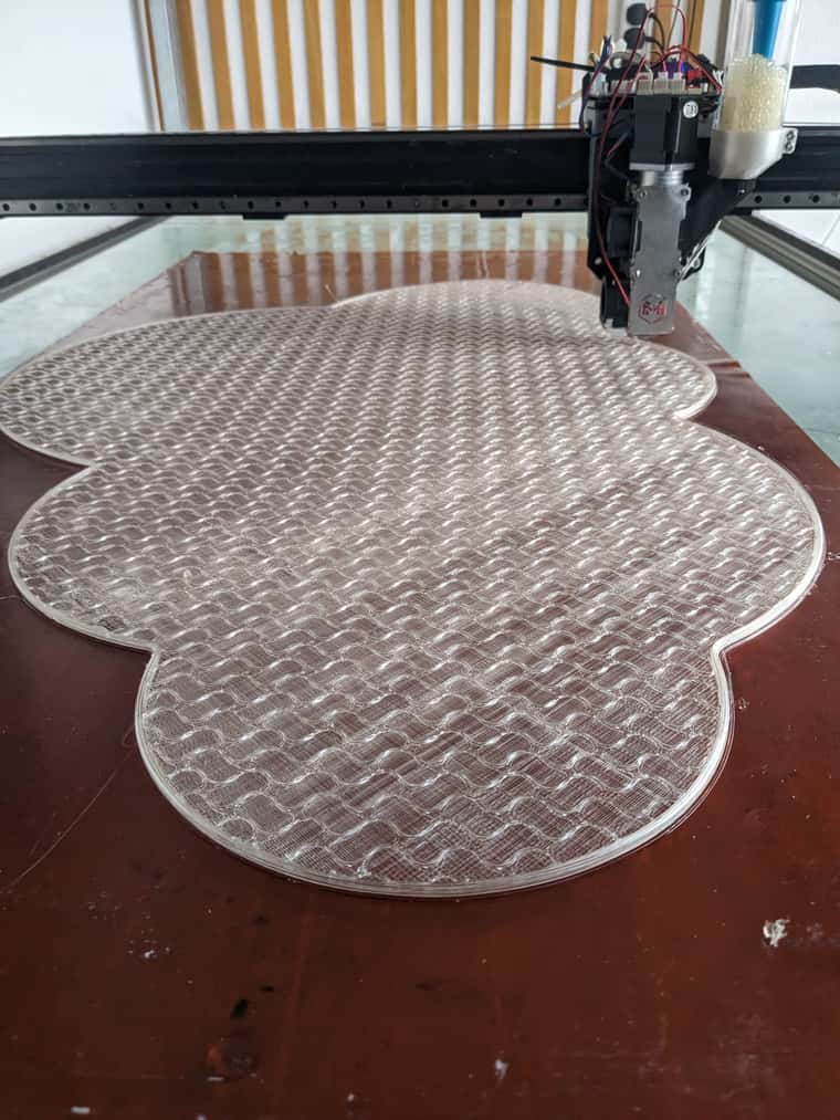
I've converted my Elegoo Giga into a Duet-controlled machine and wondered if someone could help translate the start code that heats only the required beds (there are 4 x 400mm2) ,
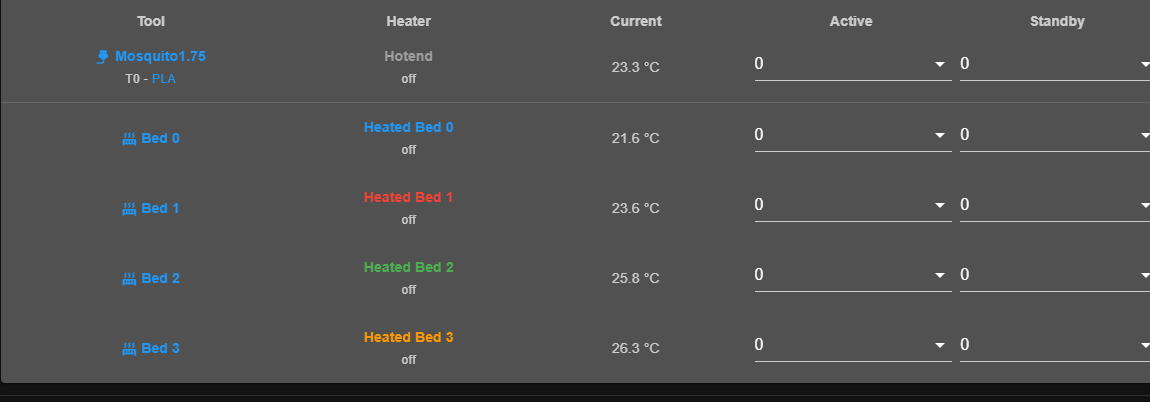
Here's my attempt, which at some point seems to override H0 (my heatbed 0) and in DWC where I have four heat beds, H0-H3, Heat bed 0 gets changed so I have two Heat Bed 1s.
;Machine_use_extruders:1
;TIME:
M400 ; wait for buffer to clear
;[printer_model]
;initial_filament:{filament_type[initial_extruder]}
;curr_bed_type={curr_bed_type}
M220 S100 ;Set the feed speed to 100%
M221 S100 ;Set the flow rate to 100%
M104 S140
;Giga zoned hot bed control
;Case 1
M140 S0
{if (min(print_bed_max[0], first_layer_print_min[0] + 32) - 32) < 405 && (max(0, first_layer_print_min[1])) < 402.5}
M140 H0 S[bed_temperature_initial_layer_single]
{if ((min(print_bed_max[0], max(first_layer_print_min[0] + 32, first_layer_print_max[0])))) > 405}
M140 H1 S[bed_temperature_initial_layer_single]
{endif}
{if ((first_layer_print_max[1])) > 402.5}
M140 H3 S[bed_temperature_initial_layer_single]
{endif}
{if ((min(print_bed_max[0], max(first_layer_print_min[0] + 32, first_layer_print_max[0])))) > 405 && ((first_layer_print_max[1])) > 402.5}
M140 H2 S[bed_temperature_initial_layer_single]
{endif}
{endif}

;Case 2
{if (min(print_bed_max[0], first_layer_print_min[0] + 32) - 32) < 405 && (max(0, first_layer_print_min[1])) > 402.5}
M140 H3 S[bed_temperature_initial_layer_single]
{if ((min(print_bed_max[0], max(first_layer_print_min[0] + 32, first_layer_print_max[0])))) > 405}
M140 H2 S[bed_temperature_initial_layer_single]
{endif}
{endif}

;Case 3
{if (min(print_bed_max[0], first_layer_print_min[0] + 32) - 32) > 405 && (max(0, first_layer_print_min[1])) < 402.5}
M140 H1 S[bed_temperature_initial_layer_single]
{if ((first_layer_print_max[1])) > 402.5}
M140 H2 S[bed_temperature_initial_layer_single]
{endif}
{endif}

;Case 4
{if (min(print_bed_max[0], first_layer_print_min[0] + 32) - 32) > 405 && (max(0, first_layer_print_min[1])) > 402.5}
M140 H2 S[bed_temperature_initial_layer_single]
{endif}
G90
G28 ;home
G1 Z10 F300
G1 X{print_bed_max[0]*0.75-50} Y25.5 F6000
;
;Giga zoned hot bed control
;Case 1
{if (min(print_bed_max[0], first_layer_print_min[0] + 32) - 32) < 405 && (max(0, first_layer_print_min[1])) < 402.5}
M190 H0 S[bed_temperature_initial_layer_single]
{if ((min(print_bed_max[0], max(first_layer_print_min[0] + 32, first_layer_print_max[0])))) > 405}
M190 H1 S[bed_temperature_initial_layer_single]
{endif}
{if ((first_layer_print_max[1])) > 402.5}
M190 H3 S[bed_temperature_initial_layer_single]
{endif}
{if ((min(print_bed_max[0], max(first_layer_print_min[0] + 32, first_layer_print_max[0])))) > 405 && ((first_layer_print_max[1])) > 402.5}
M190 H2 S[bed_temperature_initial_layer_single]
{endif}
{endif}

;Case 2
{if (min(print_bed_max[0], first_layer_print_min[0] + 32) - 32) < 405 && (max(0, first_layer_print_min[1])) > 402.5}
M190 H3 S[bed_temperature_initial_layer_single]
{if ((min(print_bed_max[0], max(first_layer_print_min[0] + 32, first_layer_print_max[0])))) > 405}
M190 H2 S[bed_temperature_initial_layer_single]
{endif}
{endif}

;Case 3
{if (min(print_bed_max[0], first_layer_print_min[0] + 32) - 32) > 405 && (max(0, first_layer_print_min[1])) < 402.5}
M190 H1 S[bed_temperature_initial_layer_single]
{if ((first_layer_print_max[1])) > 402.5}
M190 H2 S[bed_temperature_initial_layer_single]
{endif}
{endif}

;Case 4
{if (min(print_bed_max[0], first_layer_print_min[0] + 32) - 32) > 405 && (max(0, first_layer_print_min[1])) > 402.5}
M190 H2 S[bed_temperature_initial_layer_single]
{endif}
G1 Z0.4 F300
M109 S[nozzle_temperature_initial_layer]
G92 E0 ;Reset Extruder
G1 X{print_bed_max[0]*0.75+50} E30 F400 ;Draw the first line
G1 Z0.6 F120.0 ;Move to side a little
G1 X{print_bed_max[0]*0.75+47} F3000
G92 E0 ;Reset Extruder
;LAYER_COUNT:[total_layer_count]
;LAYER:0

G29 S1

M376 H10
Here's the code from Elegoo -
;Machine_use_extruders:1
;TIME:
M400 ; wait for buffer to clear
;[printer_model]
;initial_filament:{filament_type[initial_extruder]}
;curr_bed_type={curr_bed_type}
M220 S100 ;Set the feed speed to 100%
M221 S100 ;Set the flow rate to 100%
M104 S140
;Giga zoned hot bed control
;Case 1
M140 S0
{if (min(print_bed_max[0], first_layer_print_min[0] + 32) - 32) < 405 && (max(0, first_layer_print_min[1])) < 402.5}
M140 T0 S[bed_temperature_initial_layer_single]
{if ((min(print_bed_max[0], max(first_layer_print_min[0] + 32, first_layer_print_max[0])))) > 405}
M140 T1 S[bed_temperature_initial_layer_single]
{endif}
{if ((first_layer_print_max[1])) > 402.5}
M140 T3 S[bed_temperature_initial_layer_single]
{endif}
{if ((min(print_bed_max[0], max(first_layer_print_min[0] + 32, first_layer_print_max[0])))) > 405 && ((first_layer_print_max[1])) > 402.5}
M140 T2 S[bed_temperature_initial_layer_single]
{endif}
{endif}

;Case 2
{if (min(print_bed_max[0], first_layer_print_min[0] + 32) - 32) < 405 && (max(0, first_layer_print_min[1])) > 402.5}
M140 T3 S[bed_temperature_initial_layer_single]
{if ((min(print_bed_max[0], max(first_layer_print_min[0] + 32, first_layer_print_max[0])))) > 405}
M140 T2 S[bed_temperature_initial_layer_single]
{endif}
{endif}

;Case 3
{if (min(print_bed_max[0], first_layer_print_min[0] + 32) - 32) > 405 && (max(0, first_layer_print_min[1])) < 402.5}
M140 T1 S[bed_temperature_initial_layer_single]
{if ((first_layer_print_max[1])) > 402.5}
M140 T2 S[bed_temperature_initial_layer_single]
{endif}
{endif}

;Case 4
{if (min(print_bed_max[0], first_layer_print_min[0] + 32) - 32) > 405 && (max(0, first_layer_print_min[1])) > 402.5}
M140 T2 S[bed_temperature_initial_layer_single]
{endif}
G90
G28 ;home
G1 Z10 F300
G1 X{print_bed_max[0]*0.75-50} Y0.5 F6000
;
;Giga zoned hot bed control
;Case 1
{if (min(print_bed_max[0], first_layer_print_min[0] + 32) - 32) < 405 && (max(0, first_layer_print_min[1])) < 402.5}
M190 T0 S[bed_temperature_initial_layer_single]
{if ((min(print_bed_max[0], max(first_layer_print_min[0] + 32, first_layer_print_max[0])))) > 405}
M190 T1 S[bed_temperature_initial_layer_single]
{endif}
{if ((first_layer_print_max[1])) > 402.5}
M190 T3 S[bed_temperature_initial_layer_single]
{endif}
{if ((min(print_bed_max[0], max(first_layer_print_min[0] + 32, first_layer_print_max[0])))) > 405 && ((first_layer_print_max[1])) > 402.5}
M190 T2 S[bed_temperature_initial_layer_single]
{endif}
{endif}

;Case 2
{if (min(print_bed_max[0], first_layer_print_min[0] + 32) - 32) < 405 && (max(0, first_layer_print_min[1])) > 402.5}
M190 T3 S[bed_temperature_initial_layer_single]
{if ((min(print_bed_max[0], max(first_layer_print_min[0] + 32, first_layer_print_max[0])))) > 405}
M190 T2 S[bed_temperature_initial_layer_single]
{endif}
{endif}

;Case 3
{if (min(print_bed_max[0], first_layer_print_min[0] + 32) - 32) > 405 && (max(0, first_layer_print_min[1])) < 402.5}
M190 T1 S[bed_temperature_initial_layer_single]
{if ((first_layer_print_max[1])) > 402.5}
M190 T2 S[bed_temperature_initial_layer_single]
{endif}
{endif}

;Case 4
{if (min(print_bed_max[0], first_layer_print_min[0] + 32) - 32) > 405 && (max(0, first_layer_print_min[1])) > 402.5}
M190 T2 S[bed_temperature_initial_layer_single]
{endif}
G1 Z0.4 F300
M109 S[nozzle_temperature_initial_layer]
G92 E0 ;Reset Extruder
G1 X{print_bed_max[0]*0.75+50} E30 F400 ;Draw the first line
G1 Z0.6 F120.0 ;Move to side a little
G1 X{print_bed_max[0]*0.75+47} F3000
G92 E0 ;Reset Extruder
;LAYER_COUNT:[total_layer_count]
;LAYER:0
If anyone has any thoughts on how this could be modified to Duet appropriate code I'd appreciate it 
Thanks
Nate
ps my config -
; Configuration file for RepRapFirmware on Duet 3 Main Board 6HC
; executed by the firmware on start-up
;
; generated by RepRapFirmware Configuration Tool v3.5.8 on Thu Dec 12 2024 17:45:30 GMT+0000 (Greenwich Mean Time)

; General
G90 ; absolute coordinates
M83 ; relative extruder moves
M550 P"GigaDAM" ; set hostname

; Accessories
M575 P1 S0 B57600 ; configure PanelDue support

; Network


; Wait a moment for the CAN expansion boards to become available
G4 S5

; Accelerometers
M955 P121.0 I54 ; configure accelerometer on board #121

; Kinematics
M669 K0 ; configure Cartesian kinematics


; Smart Drivers
M569 P0.0 S0 D2 ; driver 0.0 goes forwards (Y axis)
M569 P0.1 S1 D2 ; driver 0.1 goes forwards (X axis)
M569 P0.2 S1 D2 ; driver 0.2 goes forwards (Z axis)
M569 P0.3 S0 D2 ; driver 0.3 goes forwards (Z axis)
M569 P121.0 S1 D2 ; driver 121.0 goes forwards (extruder 0)

; Motor Idle Current Reduction
M906 I30 ; set motor current idle factor
M84 S30 ; set motor current idle timeout

; Axes
M584 X0.1 Y0.0 Z0.2:0.3 ; set axis mapping
M671 X-20:870 Y0:0 S1.5 ; position of leadscrew/bed pivot point at left and right of X axis
M350 X16 Y16 Z16 I1 ; configure microstepping with interpolation
M906 X1950 Y2050 Z1400 ; set axis driver currents
M92 X53.875 Y134.45 Z1005 ; configure steps per mm
M208 X0:800 Y10:800 Z0:1020 ; set minimum and maximum axis limits
M566 X900 Y400 Z12 ; set maximum instantaneous speed changes (mm/min)
M203 X12000 Y12000 Z1080 ; set maximum speeds (mm/min)
M201 X500 Y500 Z20 ; set accelerations (mm/s^2)

; Extruders
M584 E121.0 ; set extruder mapping
M350 E16 I1 ; configure microstepping with interpolation
M906 E900 ; set extruder driver currents
;M92  E526 ; steps per mm 2.85 JBPlanetary
M92 E395 ; configure steps per mm 1.75 LGX
;M92 E774 ; configure steps per mm Orbiter
M566 E120 ; set maximum instantaneous speed changes (mm/min)
M203 E5600 ; set maximum speeds (mm/min)
M201 E250 ; set accelerations (mm/s^2)


; Probes
;M558 K0 P8 C"!121.io0.in" H5 F800:80 T8000 ; 2.85 probe configure unfiltered digital probe via slot #0
M558 K0 P8 C"121.io0.in" H5 R0.4 A3 S0.02 F800:80 T8000 ; 1.75 probe configure unfiltered digital probe via slot #0
G31 P500 X7 Y-4 Z0.320  ; set Z probe trigger value, offset and trigger height
M557 X25:780 Y75:780 S40


; Endstops
M574 X2 P"io4.in" S1 ; configure X axis endstop
M574 Y2 P"io2.in" S1 ; configure Y axis endstop
M574 Z1 S2
;M574 Z1 P"io1.in+io3.in" S1 ; configure Z axis endstop

;Filament Sensor
M591 D0 P1 C"121.io1.in" S1 ; simple sensor (high signal when filament present) connected to IO_4 for drive 0, enabled


; Sensors
M308 S0 P"temp0" Y"thermistor" A"Heated Bed 0" T100000 B4725 C7.06e-8 ; configure sensor #0
M308 S1 P"temp1" Y"thermistor" A"Heated Bed 1" T100000 B4725 C7.06e-8 ; configure sensor #1
M308 S2 P"temp2" Y"thermistor" A"Heated Bed 2" T100000 B4725 C7.06e-8 ; configure sensor #2
M308 S3 P"temp3" Y"thermistor" A"Heated Bed 3" T100000 B4725 C7.06e-8 ; configure sensor #3
M308 S4 P"121.temp0" Y"thermistor" A"Hotend" T100000 B4725 C7.06e-8 ; configure sensor #4

; Heaters
M950 H0 C"out4" T0 ; create heater #0
M143 H0 P0 T0 C0 S110 A0 ; configure heater monitor #0 for heater #0
M307 H0 R0.130 K0.159:0.000 D2.97 E1.35 S1.00 B0
;M307 H0 R2.43 D5.5 E1.35 K0.56 B1 ; configure model of heater #0

M950 H1 C"out5" T1 ; create heater #1
M143 H1 P0 T1 C0 S110 A0 ; configure heater monitor #0 for heater #1
M307 H0 R0.130 K0.159:0.000 D2.97 E1.35 S1.00 B0
;M307 H1 R2.43 D5.5 E1.35 K0.56 B0 ; configure model of heater #1

M950 H2 C"out6" T2 ; create heater #2
M143 H2 P0 T2 C0 S110 A0 ; configure heater monitor #0 for heater #2
M307 H0 R0.130 K0.159:0.000 D2.97 E1.35 S1.00 B0
;M307 H2 R2.43 D5.5 E1.35 K0.56 B0 ; configure model of heater #2

M950 H3 C"out7" T3 ; create heater #3
M143 H3 P0 T3 C0 S110 A0 ; configure heater monitor #0 for heater #3
M307 H0 R0.130 K0.159:0.000 D2.97 E1.35 S1.00 B0
;M307 H3 R2.43 D5.5 E1.35 K0.56 B0 ; configure model of heater #3

M950 H4 C"121.out0" T4 ; create heater #4
M143 H4 P0 T4 C0 S285 A0 ; configure heater monitor #0 for heater #4
M307 H4 R2.832 K0.407:0.000 D13.13 E1.35 S1.00 B0 V24.8 ; 1.75mm Heater
;M307 H4 R3.885 K0.568:0.424 D9.79 E1.35 S1.00 B0 V24.2 ; 2.85mm Mosquito Heater
;M307 H4 R3.602 K0.516:0.010 D8.95 E1.35 S1.00 B0 V23.3 ; configure model of heater #4 previous 2.85 Extruder


; Heated beds
M140 P0 H0 ; configure heated bed #0
M140 P1 H1 ; configure heated bed #1
M140 P2 H2 ; configure heated bed #2
M140 P3 H3 ; configure heated bed #3

; Fans
M950 F0 C"121.out1" ; create fan #0
M106 P0 S0 L0 X1 B0.1 ; configure fan #0
M950 F1 C"121.out2" ; create fan #1
M106 P1 S0 B0.1 H4 T45 ; configure fan #1

; Tools
;M563 P0 S"Mosquito2.85" D0 H4 F0 ; create tool #0
M563 P0 S"Mosquito1.75" D0 H4 F0 ; create tool #0
M568 P0 R0 S0 ; set initial tool #0 active and standby temperatures to 0C

; Miscellaneous

; Custom settings
M911 S21.0 R23.0 P"M913 X0 Y0 G91 M83 G1 Z3 E-5 F1000"
")