@jay_s_uk ---
Thanks, after thinking about what you said I tried swapping my H and L in the CAN connections and I've got one of three tool boards running now.

Nate
@jay_s_uk ---
Thanks, after thinking about what you said I tried swapping my H and L in the CAN connections and I've got one of three tool boards running now.
Nate
Sure thing,
Just to say that I was running the 1LC previously with a CAN connection and it ran well, I'll take some photos and post my config.
-N
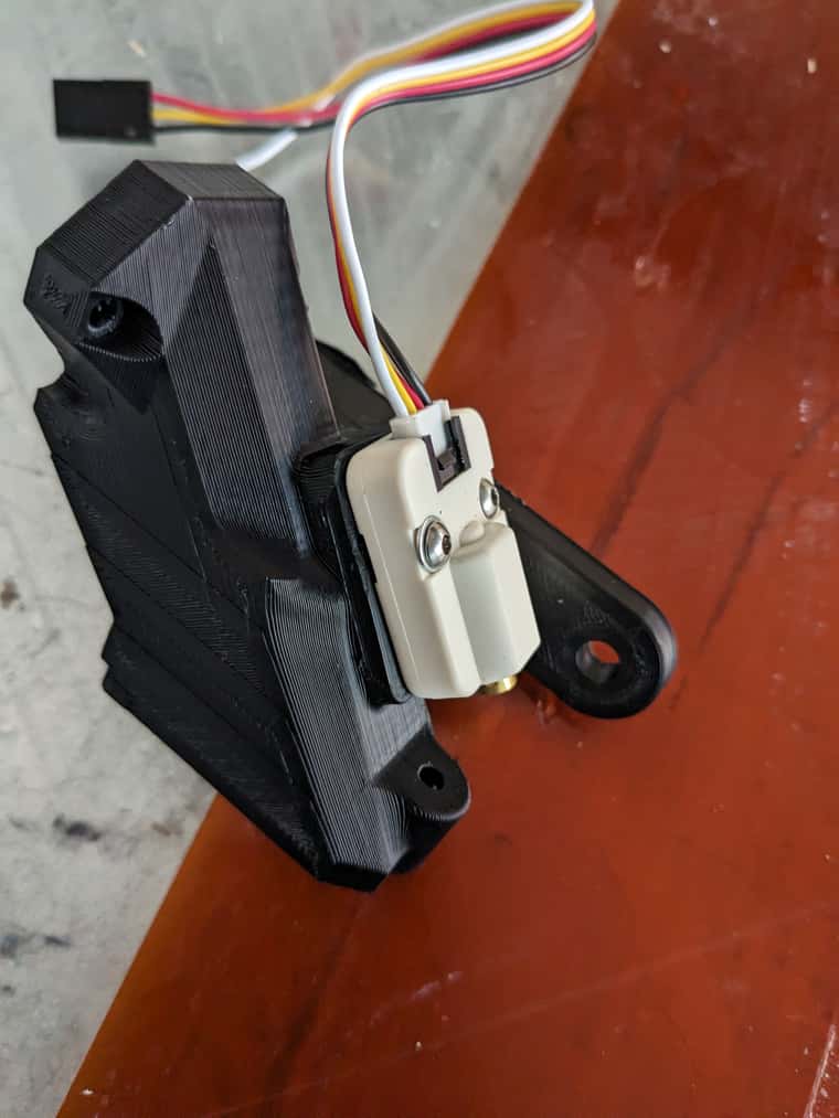
Hi @jay_s_uk ,
Have swapped from a Duet Toolboard to this and flashed the firmware (I think) and connected it to the CAN port on my Duet-modified OrangeStorm Giga and I'm unable to connect to it.
Set the DIP switches to this -

But the Ali site says the exact opposite -

I'm assuming the info on the TeamGloomy page is the correct one, I've flipped the 120ohm jumper up and no joy- I get power lights and a rapidly flashing "working" LED but it just stays rapidly flashing.
So I'm stumped, the error I get when I boot is :
CAN response timeout: board 124
Followed the flashing method, saw the drive put the firmware on it and the working light went solid and then started rapidly flashing again so I assume it flashed properly. Could it be that I received a SHT36v3 and not a SHT36 MAX V3? Is there some way of identifying it on the board?
Thanks in advance,
Nate
Hi everyone,
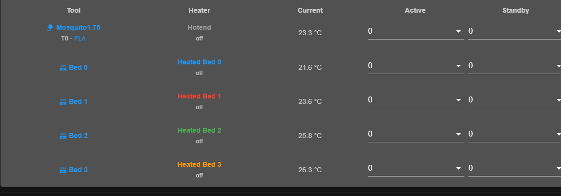
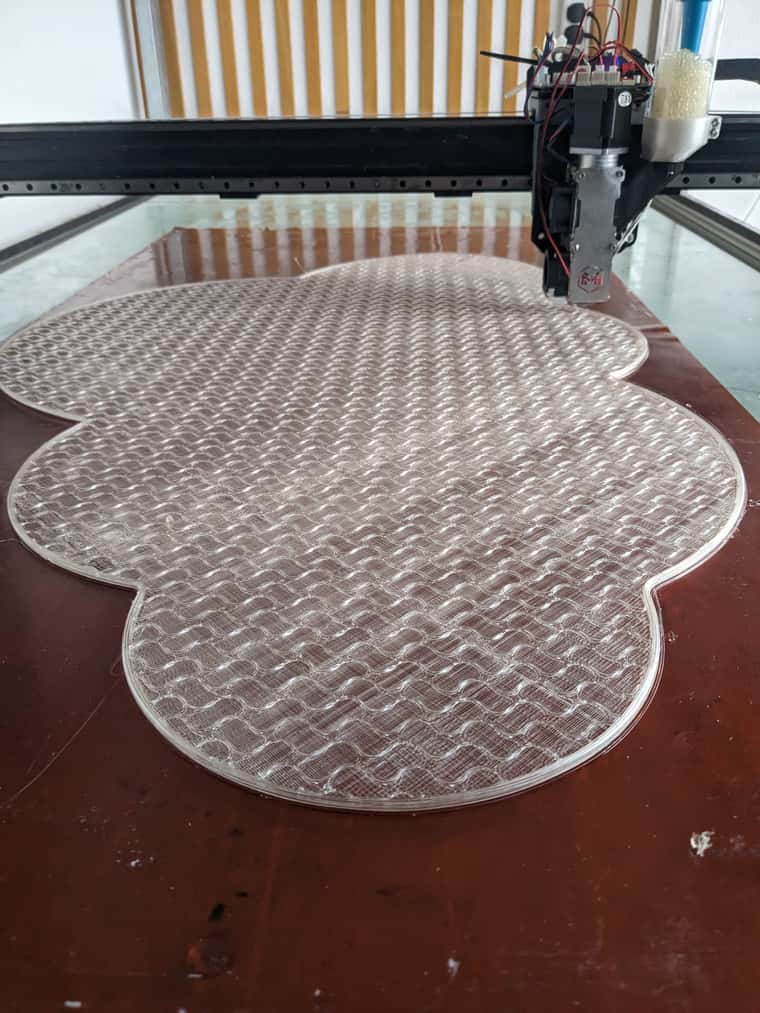
I've converted my Elegoo Giga into a Duet-controlled machine and wondered if someone could help translate the start code that heats only the required beds (there are 4 x 400mm2) ,
Here's my attempt, which at some point seems to override H0 (my heatbed 0) and in DWC where I have four heat beds, H0-H3, Heat bed 0 gets changed so I have two Heat Bed 1s.
;Machine_use_extruders:1
;TIME:
M400 ; wait for buffer to clear
;[printer_model]
;initial_filament:{filament_type[initial_extruder]}
;curr_bed_type={curr_bed_type}
M220 S100 ;Set the feed speed to 100%
M221 S100 ;Set the flow rate to 100%
M104 S140
;Giga zoned hot bed control
;Case 1
M140 S0
{if (min(print_bed_max[0], first_layer_print_min[0] + 32) - 32) < 405 && (max(0, first_layer_print_min[1])) < 402.5}
M140 H0 S[bed_temperature_initial_layer_single]
{if ((min(print_bed_max[0], max(first_layer_print_min[0] + 32, first_layer_print_max[0])))) > 405}
M140 H1 S[bed_temperature_initial_layer_single]
{endif}
{if ((first_layer_print_max[1])) > 402.5}
M140 H3 S[bed_temperature_initial_layer_single]
{endif}
{if ((min(print_bed_max[0], max(first_layer_print_min[0] + 32, first_layer_print_max[0])))) > 405 && ((first_layer_print_max[1])) > 402.5}
M140 H2 S[bed_temperature_initial_layer_single]
{endif}
{endif}

;Case 2
{if (min(print_bed_max[0], first_layer_print_min[0] + 32) - 32) < 405 && (max(0, first_layer_print_min[1])) > 402.5}
M140 H3 S[bed_temperature_initial_layer_single]
{if ((min(print_bed_max[0], max(first_layer_print_min[0] + 32, first_layer_print_max[0])))) > 405}
M140 H2 S[bed_temperature_initial_layer_single]
{endif}
{endif}

;Case 3
{if (min(print_bed_max[0], first_layer_print_min[0] + 32) - 32) > 405 && (max(0, first_layer_print_min[1])) < 402.5}
M140 H1 S[bed_temperature_initial_layer_single]
{if ((first_layer_print_max[1])) > 402.5}
M140 H2 S[bed_temperature_initial_layer_single]
{endif}
{endif}

;Case 4
{if (min(print_bed_max[0], first_layer_print_min[0] + 32) - 32) > 405 && (max(0, first_layer_print_min[1])) > 402.5}
M140 H2 S[bed_temperature_initial_layer_single]
{endif}
G90
G28 ;home
G1 Z10 F300
G1 X{print_bed_max[0]*0.75-50} Y25.5 F6000
;
;Giga zoned hot bed control
;Case 1
{if (min(print_bed_max[0], first_layer_print_min[0] + 32) - 32) < 405 && (max(0, first_layer_print_min[1])) < 402.5}
M190 H0 S[bed_temperature_initial_layer_single]
{if ((min(print_bed_max[0], max(first_layer_print_min[0] + 32, first_layer_print_max[0])))) > 405}
M190 H1 S[bed_temperature_initial_layer_single]
{endif}
{if ((first_layer_print_max[1])) > 402.5}
M190 H3 S[bed_temperature_initial_layer_single]
{endif}
{if ((min(print_bed_max[0], max(first_layer_print_min[0] + 32, first_layer_print_max[0])))) > 405 && ((first_layer_print_max[1])) > 402.5}
M190 H2 S[bed_temperature_initial_layer_single]
{endif}
{endif}

;Case 2
{if (min(print_bed_max[0], first_layer_print_min[0] + 32) - 32) < 405 && (max(0, first_layer_print_min[1])) > 402.5}
M190 H3 S[bed_temperature_initial_layer_single]
{if ((min(print_bed_max[0], max(first_layer_print_min[0] + 32, first_layer_print_max[0])))) > 405}
M190 H2 S[bed_temperature_initial_layer_single]
{endif}
{endif}

;Case 3
{if (min(print_bed_max[0], first_layer_print_min[0] + 32) - 32) > 405 && (max(0, first_layer_print_min[1])) < 402.5}
M190 H1 S[bed_temperature_initial_layer_single]
{if ((first_layer_print_max[1])) > 402.5}
M190 H2 S[bed_temperature_initial_layer_single]
{endif}
{endif}

;Case 4
{if (min(print_bed_max[0], first_layer_print_min[0] + 32) - 32) > 405 && (max(0, first_layer_print_min[1])) > 402.5}
M190 H2 S[bed_temperature_initial_layer_single]
{endif}
G1 Z0.4 F300
M109 S[nozzle_temperature_initial_layer]
G92 E0 ;Reset Extruder
G1 X{print_bed_max[0]*0.75+50} E30 F400 ;Draw the first line
G1 Z0.6 F120.0 ;Move to side a little
G1 X{print_bed_max[0]*0.75+47} F3000
G92 E0 ;Reset Extruder
;LAYER_COUNT:[total_layer_count]
;LAYER:0

G29 S1

M376 H10
Here's the code from Elegoo -
;Machine_use_extruders:1
;TIME:
M400 ; wait for buffer to clear
;[printer_model]
;initial_filament:{filament_type[initial_extruder]}
;curr_bed_type={curr_bed_type}
M220 S100 ;Set the feed speed to 100%
M221 S100 ;Set the flow rate to 100%
M104 S140
;Giga zoned hot bed control
;Case 1
M140 S0
{if (min(print_bed_max[0], first_layer_print_min[0] + 32) - 32) < 405 && (max(0, first_layer_print_min[1])) < 402.5}
M140 T0 S[bed_temperature_initial_layer_single]
{if ((min(print_bed_max[0], max(first_layer_print_min[0] + 32, first_layer_print_max[0])))) > 405}
M140 T1 S[bed_temperature_initial_layer_single]
{endif}
{if ((first_layer_print_max[1])) > 402.5}
M140 T3 S[bed_temperature_initial_layer_single]
{endif}
{if ((min(print_bed_max[0], max(first_layer_print_min[0] + 32, first_layer_print_max[0])))) > 405 && ((first_layer_print_max[1])) > 402.5}
M140 T2 S[bed_temperature_initial_layer_single]
{endif}
{endif}

;Case 2
{if (min(print_bed_max[0], first_layer_print_min[0] + 32) - 32) < 405 && (max(0, first_layer_print_min[1])) > 402.5}
M140 T3 S[bed_temperature_initial_layer_single]
{if ((min(print_bed_max[0], max(first_layer_print_min[0] + 32, first_layer_print_max[0])))) > 405}
M140 T2 S[bed_temperature_initial_layer_single]
{endif}
{endif}

;Case 3
{if (min(print_bed_max[0], first_layer_print_min[0] + 32) - 32) > 405 && (max(0, first_layer_print_min[1])) < 402.5}
M140 T1 S[bed_temperature_initial_layer_single]
{if ((first_layer_print_max[1])) > 402.5}
M140 T2 S[bed_temperature_initial_layer_single]
{endif}
{endif}

;Case 4
{if (min(print_bed_max[0], first_layer_print_min[0] + 32) - 32) > 405 && (max(0, first_layer_print_min[1])) > 402.5}
M140 T2 S[bed_temperature_initial_layer_single]
{endif}
G90
G28 ;home
G1 Z10 F300
G1 X{print_bed_max[0]*0.75-50} Y0.5 F6000
;
;Giga zoned hot bed control
;Case 1
{if (min(print_bed_max[0], first_layer_print_min[0] + 32) - 32) < 405 && (max(0, first_layer_print_min[1])) < 402.5}
M190 T0 S[bed_temperature_initial_layer_single]
{if ((min(print_bed_max[0], max(first_layer_print_min[0] + 32, first_layer_print_max[0])))) > 405}
M190 T1 S[bed_temperature_initial_layer_single]
{endif}
{if ((first_layer_print_max[1])) > 402.5}
M190 T3 S[bed_temperature_initial_layer_single]
{endif}
{if ((min(print_bed_max[0], max(first_layer_print_min[0] + 32, first_layer_print_max[0])))) > 405 && ((first_layer_print_max[1])) > 402.5}
M190 T2 S[bed_temperature_initial_layer_single]
{endif}
{endif}

;Case 2
{if (min(print_bed_max[0], first_layer_print_min[0] + 32) - 32) < 405 && (max(0, first_layer_print_min[1])) > 402.5}
M190 T3 S[bed_temperature_initial_layer_single]
{if ((min(print_bed_max[0], max(first_layer_print_min[0] + 32, first_layer_print_max[0])))) > 405}
M190 T2 S[bed_temperature_initial_layer_single]
{endif}
{endif}

;Case 3
{if (min(print_bed_max[0], first_layer_print_min[0] + 32) - 32) > 405 && (max(0, first_layer_print_min[1])) < 402.5}
M190 T1 S[bed_temperature_initial_layer_single]
{if ((first_layer_print_max[1])) > 402.5}
M190 T2 S[bed_temperature_initial_layer_single]
{endif}
{endif}

;Case 4
{if (min(print_bed_max[0], first_layer_print_min[0] + 32) - 32) > 405 && (max(0, first_layer_print_min[1])) > 402.5}
M190 T2 S[bed_temperature_initial_layer_single]
{endif}
G1 Z0.4 F300
M109 S[nozzle_temperature_initial_layer]
G92 E0 ;Reset Extruder
G1 X{print_bed_max[0]*0.75+50} E30 F400 ;Draw the first line
G1 Z0.6 F120.0 ;Move to side a little
G1 X{print_bed_max[0]*0.75+47} F3000
G92 E0 ;Reset Extruder
;LAYER_COUNT:[total_layer_count]
;LAYER:0
If anyone has any thoughts on how this could be modified to Duet appropriate code I'd appreciate it 
Thanks
Nate
ps my config -
; Configuration file for RepRapFirmware on Duet 3 Main Board 6HC
; executed by the firmware on start-up
;
; generated by RepRapFirmware Configuration Tool v3.5.8 on Thu Dec 12 2024 17:45:30 GMT+0000 (Greenwich Mean Time)

; General
G90 ; absolute coordinates
M83 ; relative extruder moves
M550 P"GigaDAM" ; set hostname

; Accessories
M575 P1 S0 B57600 ; configure PanelDue support

; Network


; Wait a moment for the CAN expansion boards to become available
G4 S5

; Accelerometers
M955 P121.0 I54 ; configure accelerometer on board #121

; Kinematics
M669 K0 ; configure Cartesian kinematics


; Smart Drivers
M569 P0.0 S0 D2 ; driver 0.0 goes forwards (Y axis)
M569 P0.1 S1 D2 ; driver 0.1 goes forwards (X axis)
M569 P0.2 S1 D2 ; driver 0.2 goes forwards (Z axis)
M569 P0.3 S0 D2 ; driver 0.3 goes forwards (Z axis)
M569 P121.0 S1 D2 ; driver 121.0 goes forwards (extruder 0)

; Motor Idle Current Reduction
M906 I30 ; set motor current idle factor
M84 S30 ; set motor current idle timeout

; Axes
M584 X0.1 Y0.0 Z0.2:0.3 ; set axis mapping
M671 X-20:870 Y0:0 S1.5 ; position of leadscrew/bed pivot point at left and right of X axis
M350 X16 Y16 Z16 I1 ; configure microstepping with interpolation
M906 X1950 Y2050 Z1400 ; set axis driver currents
M92 X53.875 Y134.45 Z1005 ; configure steps per mm
M208 X0:800 Y10:800 Z0:1020 ; set minimum and maximum axis limits
M566 X900 Y400 Z12 ; set maximum instantaneous speed changes (mm/min)
M203 X12000 Y12000 Z1080 ; set maximum speeds (mm/min)
M201 X500 Y500 Z20 ; set accelerations (mm/s^2)

; Extruders
M584 E121.0 ; set extruder mapping
M350 E16 I1 ; configure microstepping with interpolation
M906 E900 ; set extruder driver currents
;M92  E526 ; steps per mm 2.85 JBPlanetary
M92 E395 ; configure steps per mm 1.75 LGX
;M92 E774 ; configure steps per mm Orbiter
M566 E120 ; set maximum instantaneous speed changes (mm/min)
M203 E5600 ; set maximum speeds (mm/min)
M201 E250 ; set accelerations (mm/s^2)


; Probes
;M558 K0 P8 C"!121.io0.in" H5 F800:80 T8000 ; 2.85 probe configure unfiltered digital probe via slot #0
M558 K0 P8 C"121.io0.in" H5 R0.4 A3 S0.02 F800:80 T8000 ; 1.75 probe configure unfiltered digital probe via slot #0
G31 P500 X7 Y-4 Z0.320  ; set Z probe trigger value, offset and trigger height
M557 X25:780 Y75:780 S40


; Endstops
M574 X2 P"io4.in" S1 ; configure X axis endstop
M574 Y2 P"io2.in" S1 ; configure Y axis endstop
M574 Z1 S2
;M574 Z1 P"io1.in+io3.in" S1 ; configure Z axis endstop

;Filament Sensor
M591 D0 P1 C"121.io1.in" S1 ; simple sensor (high signal when filament present) connected to IO_4 for drive 0, enabled


; Sensors
M308 S0 P"temp0" Y"thermistor" A"Heated Bed 0" T100000 B4725 C7.06e-8 ; configure sensor #0
M308 S1 P"temp1" Y"thermistor" A"Heated Bed 1" T100000 B4725 C7.06e-8 ; configure sensor #1
M308 S2 P"temp2" Y"thermistor" A"Heated Bed 2" T100000 B4725 C7.06e-8 ; configure sensor #2
M308 S3 P"temp3" Y"thermistor" A"Heated Bed 3" T100000 B4725 C7.06e-8 ; configure sensor #3
M308 S4 P"121.temp0" Y"thermistor" A"Hotend" T100000 B4725 C7.06e-8 ; configure sensor #4

; Heaters
M950 H0 C"out4" T0 ; create heater #0
M143 H0 P0 T0 C0 S110 A0 ; configure heater monitor #0 for heater #0
M307 H0 R0.130 K0.159:0.000 D2.97 E1.35 S1.00 B0
;M307 H0 R2.43 D5.5 E1.35 K0.56 B1 ; configure model of heater #0

M950 H1 C"out5" T1 ; create heater #1
M143 H1 P0 T1 C0 S110 A0 ; configure heater monitor #0 for heater #1
M307 H0 R0.130 K0.159:0.000 D2.97 E1.35 S1.00 B0
;M307 H1 R2.43 D5.5 E1.35 K0.56 B0 ; configure model of heater #1

M950 H2 C"out6" T2 ; create heater #2
M143 H2 P0 T2 C0 S110 A0 ; configure heater monitor #0 for heater #2
M307 H0 R0.130 K0.159:0.000 D2.97 E1.35 S1.00 B0
;M307 H2 R2.43 D5.5 E1.35 K0.56 B0 ; configure model of heater #2

M950 H3 C"out7" T3 ; create heater #3
M143 H3 P0 T3 C0 S110 A0 ; configure heater monitor #0 for heater #3
M307 H0 R0.130 K0.159:0.000 D2.97 E1.35 S1.00 B0
;M307 H3 R2.43 D5.5 E1.35 K0.56 B0 ; configure model of heater #3

M950 H4 C"121.out0" T4 ; create heater #4
M143 H4 P0 T4 C0 S285 A0 ; configure heater monitor #0 for heater #4
M307 H4 R2.832 K0.407:0.000 D13.13 E1.35 S1.00 B0 V24.8 ; 1.75mm Heater
;M307 H4 R3.885 K0.568:0.424 D9.79 E1.35 S1.00 B0 V24.2 ; 2.85mm Mosquito Heater
;M307 H4 R3.602 K0.516:0.010 D8.95 E1.35 S1.00 B0 V23.3 ; configure model of heater #4 previous 2.85 Extruder


; Heated beds
M140 P0 H0 ; configure heated bed #0
M140 P1 H1 ; configure heated bed #1
M140 P2 H2 ; configure heated bed #2
M140 P3 H3 ; configure heated bed #3

; Fans
M950 F0 C"121.out1" ; create fan #0
M106 P0 S0 L0 X1 B0.1 ; configure fan #0
M950 F1 C"121.out2" ; create fan #1
M106 P1 S0 B0.1 H4 T45 ; configure fan #1

; Tools
;M563 P0 S"Mosquito2.85" D0 H4 F0 ; create tool #0
M563 P0 S"Mosquito1.75" D0 H4 F0 ; create tool #0
M568 P0 R0 S0 ; set initial tool #0 active and standby temperatures to 0C

; Miscellaneous

; Custom settings
M911 S21.0 R23.0 P"M913 X0 Y0 G91 M83 G1 Z3 E-5 F1000"
Hi,
I've recently installed the Motion Plugin and it all went well to start until I ran into the same problem as @kiendeleo . I've plugged in an external USB and restarted after reading this post (running 3.5.2) and for whatever reason it looks like it's using up the SD card space. I've had a look through the .conf file to see if I could get it to not save images and while it looks like all the settings are turned to 'off' I'm still running into the low disk space issue and failing prints. Any advice would be welcome.
Thanks
Nate
@gloomyandy Thanks, you're right, I was trying to use M671 incorrectly I think.
It is probably easiest to just write a macro for this and use that with the bed-level screw positions I've got.
-N
Thanks, had a look at M671 and it should've been obvious that there is a 4-point limitation.
For some reason, I thought I had it working on my long print bed before as a bed-leveling screw array versus a more modern pivot point definition. if that makes sense.
-N
Hi,
Previously I had a manual bed level array that had 10 positions for the Y Axis bed leveling screws (code below is now ")
M671 X75:450:825 Y0:320:635:950:1265:1585:1950:2250 P0.5
And running 3.5.0-rc3 I now get an error that says that the M671 array is too long. Is there something I'm overlooking in another setting?
For some reason, I don't have a bed.g file anymore either.
Thanks,
Nate
@OwenD Amazing thanks very much 
@OwenD Thanks, that can be run like the M106 command in the macro?
Re: Creating a timed fan Marco and Meta
Hi,
Following on this topic, I've got a similar large format Cartesian printer with a 6HC main board and 3HC expansion boards which I've equipped with a small (M5Stack) dc motor to periodically vibrate for a second to make sure pellets are not binding in the feed passage.
I've got the DC motor connected to the IO_1 of my 3rd 3HC and it runs (constantly, I know this is on 100%, this is just for testing) with this in my config.g -
; Pellet Shaker
M950 P1 C"3.io1.out"  Q450       ; create output/servo
M42 P1 S1 ; set 100% PWM on GPIO port 1
What I thought I could do is modify the code that @infiniteloop and @OwenD helped @kmoore for his pellet feed-
; filamentmonitor.g
; Check filament progress, feed pellets if needed
if job.file.fileName == null
    M99
if {{global.filamentProgress + 11500.0} <= move.extruders[0].position} ;
    set global.filamentProgress =   {move.extruders[0].position + 11500.0}
    M106 P0 S255
    G4 S3
    M106 P0 S0
But in my case, I'd like to switch on a fan connection on the 6HC using the M106 command and pulse the pellets a bit.
Is there a way of adding control over the DC motor connected to the IO_1 pins within that macro?
Thanks very much, Nate
Thanks  @droftarts
I'm guessing it's an uncommon setup as you say, in this case it's two expansion boards each with a Y motor and a Z motor and a corresponding endstop.
Ola everyone,
I've got a question about using expansion boards and M574 Axis levelling using endstops.
My machine uses one 6HC main board and three 3HC expansion boards, ideally two Z endstops (lower limit) and two Y endstops attached to two of the three 3HC expansion boards.
; Drives

;Y Lower Left
M569 P1.0 S0                                   ; physical drive 1.0 goes (right Y motor) forwards Y1
;Y Lower Right
M569 P2.1 S1                                  ; physical drive 2.1 goes (left Y motor) forwards Y2
;Y Upper Left
M569 P1.1 S1
;Y Upper Right
M569 P2.0 S0

;Z Left
M569 P1.2 S1                                   ; physical drive 1.2  (right) goes forwards Z1
;Z Right
M569 P2.2 S1                                   ; physical drive 2.2 (left) goes forwards Z1
;M569 P0.4 S0                                   ; physical drive 0.2 goes forwards U

;X
M569 P3.0 S0                                   ; physical drive 3.0 goes forwards X1
Is my Drives code and -
; Endstops
M574 X1 S1 P"!3.io0.in"                         ; configure active-high endstop for low end on X via pin 1.io0.in
M574 Y1 S1 P"!io0.in"                           ; configure active-high endstop for low end on Y via pin io0.in
M574 Z1 S1 P"!1.io0.in"
;M574 Z1 S1 P"!1.io0.in+!2.io0.in"          ; configure active-high endstops for low end on Z via pins zstop and e1stop
;M574 Z1 S1 P"!2.io0.in" 			; configure Z active-high endstop for low end pin 1.io1.in
Is my Endstops code.
At the moment I've got the axis levelling line inactive because I'm unable to get this working and wanted to see if the endstops need to be connected to the main board (or the same expansion?) or do both the drives and the associated endstops need to be connected to the same board (all on one expansion or all on the main board)
Thanks
Nate
Hi,
Checking back in to see if anyone has any advice on how best to adjust the M307 code.
Previous to 3.0 I think it heated well with no issue and the new heater algo means that it really struggles to both Autotune and reach 70-75 degrees
M308 S0 P"temp0" Y"pt1000" A"bed Heat1"        ; configure sensor 0 as thermistor on pin temp0 T100000 B4725
M950 H0 C"out1" T0                             ; create bed heater output on out0 and map it to sensor 0
;M301 H0 P-10 I0.2 D50 T0.3
M307 H0 R0.051 K0.098:0.000 D32.76 E1.35 S1.00 B0
; old M307 H0 R0.066 K0.191:0.000 D45.54 E1.35 S1.00 B0 ;M307 H0 R0.076 K0.292:0.000 D42.95 E1.35 S1.00 B0 ;M307 H0 R0.070 K0.416:0.000 D62.44 E1.35 S1.00 B0                 ; disable bang-bang mode for the bed heater and set PWM limit
M140 P0 H0                                     ; map heated bed 0 to heater 0
M143 H0 S90                                    ; set temperature limit for heater 0 to 90C
That's the current setting for one of three heat beds.
Thanks in advance,
Nate
@nxt-1 getting the similar errors via windows
"2022/06/21 14:23:53 Error while downloading rr_status: Too many errors, resetting counters and stoping track operation. Will hide consequent errors..."
Any chance there's a fix for this @Torin ?
Thanks,
Nate
@jay_s_uk Just sent you a chat message. I'm struggling with both bed heating (from 3.4.0rc1) and now what seems like a current limiting issue with steppers running from an expansion board on 3.4.0rc2. Wanted to double-check that your script above can be used to regress to 3.4.0b7 on a 6HC board + 3HC expansion?
Thanks
Nate
Hi all,
After upgrading to 3.4rc1 I've been really struggling to reach 55-60 degrees after running auto-tune half a dozen times. I've adjusted the dead time until I get an 'Error: M307: bad model parameters' error, adjusted the R value all with seemingly little effect on the heating rate.
The bed I'm heating is 3200mm long and divided into three sections. Previous to the update there was a steady temperature increase and now the heating only seems to work 2-3/10 times if the bed section is started from room temperature. If the bed error is cleared and the section turned back to active while warm (35-45) the temperature seems to struggle to heat smoothly, fluctuates around the 'warm' temperature and slightly decrease before another error/fault arises.
I've tried setting the auto-tune from room temperature to S75 with the idea that the elevated temperature might give different PID results but now the auto-tuning won't reach the set temperature and cancelled with the message 'Auto-tune cancelled because target temperature was not reached' .
I've left one section with the previous M307 code and have tried using that for the other bed sections to no avail, nearly every attempt to heat the bed(s) fails.
; Heaters
M308 S0 P"temp1" Y"pt1000" A"bed Heat1"        ; configure sensor 0 as thermistor on pin temp0
M950 H0 C"out2" T0                             ; create bed heater output on out0 and map it to sensor 0
M307 H0 R0.070 K0.416:0.000 D22.44 E1.35 S1.00 B0                 ; disable bang-bang mode for the bed heater and set PWM limit
M140 P0 H0                                     ; map heated bed 0 to heater 0
M143 H0 S90                                    ; set temperature limit for heater 0 to 90C

M308 S1 P"temp0" Y"pt1000" A"bed Heat2"        ; configure sensor 1 as pt1000 on pin temp1 (T100000 B4138)
M950 H1 C"out1" T1                             ; create bed heater output on out1 and map it to sensor 1
M307 H1 R0.083 K0.405:0.000 D15.33 E1.35 S1.00 B0                ; disable bang-bang mode for the bed heater and set PWM limit
M140 P1 H1                                     ; map heated bed 1 to heater 1

M308 S2 P"temp2" Y"thermistor" A"bed Heat3" T100000 B4138   ; configure sensor 2 as thermistor on pin temp2
M950 H2 C"out3" T2                             ; create bed heater output on out2 and map it to sensor 2
M307 H2 A32.7 C156.4 D4.0 S1.0                 ; disable bang-bang mode for the bed heater and set PWM limit
M140 P2 H2                                     ; map heated bed 1 to heater 1
Any direction would be great.
Thanks
Nate
HI @MintyTrebor ,
Have you ever come across an error like this:
Installation failed!
InvalidOperationException in InstallPlugin: Cannot perform command because the plugin service is not started
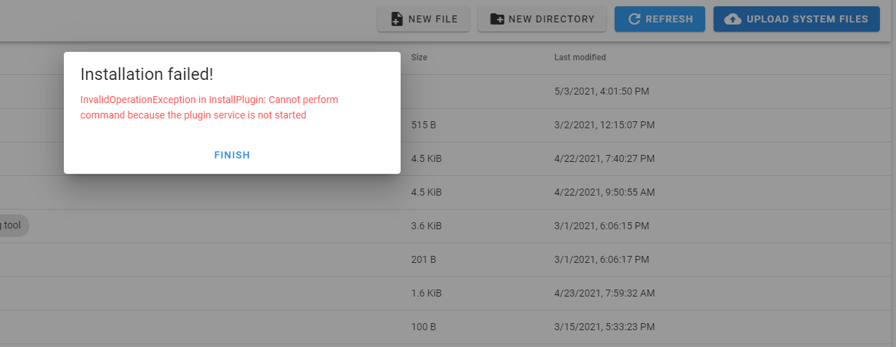
I was running 3.2.2 (this is all in SBC mode) and tried to install Alpha 0.8.17 which wouldn't work and so I upgraded DWC to 3.3.0-rc1 and then this error occurred.
Just tried Alpha 0.8.16 in case and got the same error.
Thanks-
Nate
I think this is probably what I'm seeing @droftarts and @engikeneer , while it doesn't seem to be present as much (or at all) in the Y axis, the X axis recently had a bracket upgrade that included some IGUS linear guides that seemed to be quite tight in the channel they run along.
I swapped out the helical gear from a 28 tooth one to a 44 tooth to see if that made any difference and it looks like the overall torque to move the now more supported bracket looks like I've introduced far more friction than I had before. Which in turn looks like it's either causing the motor to stall or the pinion to slip.
Thanks both for your help.
