Duet3D Logo Duet3D
    • Tags
    • Documentation
    • Order
    • Register
    • Login
    1. Home
    2. Marius Breuer
    3. Posts
    • Profile
    • Following 0
    • Followers 0
    • Topics 6
    • Posts 21
    • Best 2
    • Controversial 0
    • Groups 0

    Posts made by Marius Breuer

    • RE: PWM Fan connections for Duet 3 6XD / 6HC / 3HC

      @dc42 thanks, that's great to know. Assuming i want to use those 4-Pin IO Headers for other stuff, the PWM pin is therefore switching between a direct connection to ground and being left unconnected or does it use a pull-up? If so, to which voltage and with which resistor?

      Thanks so much for the quick help!

      Best,

      Marius

      posted in Duet Hardware and wiring
      Marius Breuerundefined
      Marius Breuer
    • PWM Fan connections for Duet 3 6XD / 6HC / 3HC

      Hi all,

      admittedly, i haven't kept up to date with the forum, but as far as I can tell this issue hasn't yet been answered/solved.
      I'm trying to run Noctua fans on an upcoming 3d printer using a 6XD + 3HC setup, however this equally applies to the 6HC.
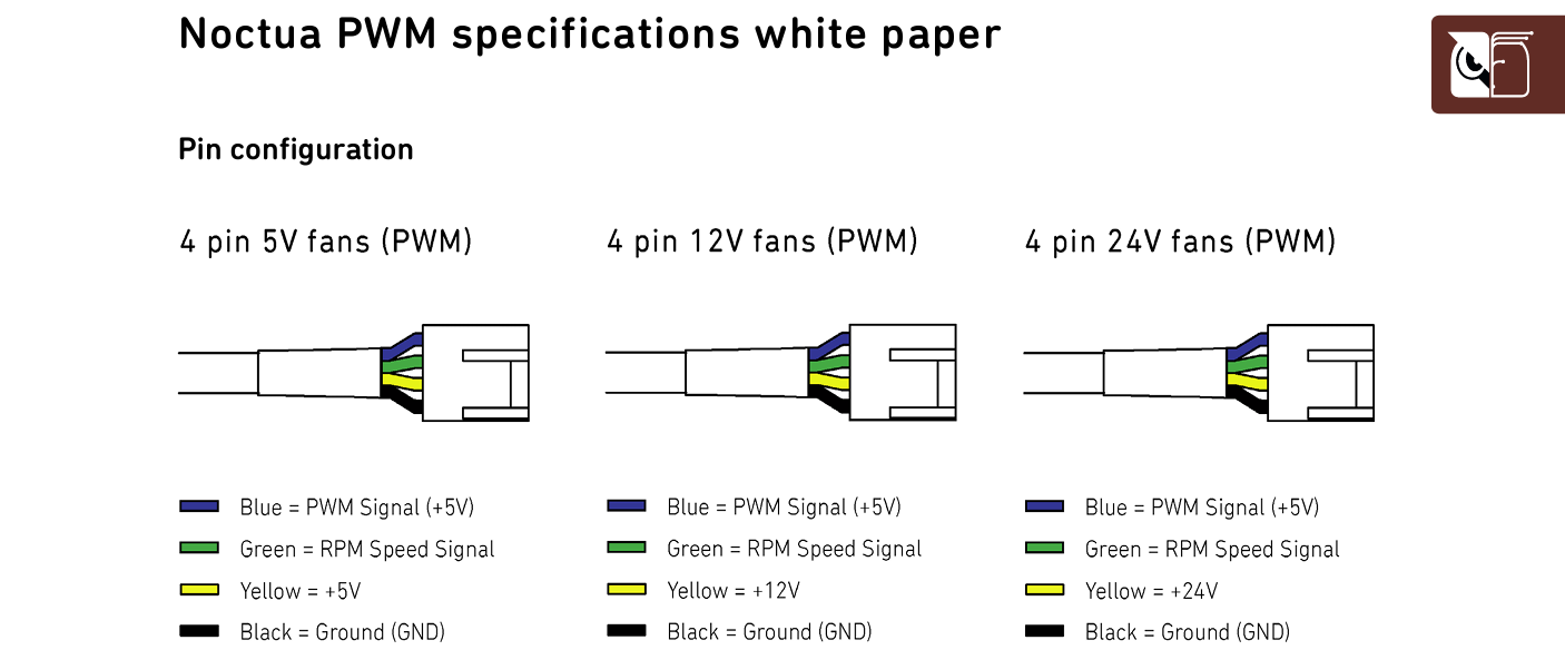
      As per their whitepaper all Noctua fans require the PWM pin to operate at a 5V level.
      fa0caef6-467d-4d4c-b831-8873b0f27a01-image.png

      The convenient 4 pin connectors can't be used because the fan supply voltage is either +12V (internal regulator) or V_FUSED (in my case 24V). Either way the PWM pin won't operate at 5V.

      Using the 5-Pin IO Modules isn't any more convenient either, as they seem to supply io[x].out with 3.3V

      Additionally i couldn't find the tacho documentation (internal pull up to 3.3V? 5V? 12V? V_FUSED?) and would like to confirm, that the current and voltage is meeting the Noctua spec:
      a2eed12d-d221-4fdc-a7b5-3596da54ce17-image.png

      I found that deviating from their requirement with Vcc 5V for their 12V fans seems to work, as long as the current limits are observed. I have used a diode (seen in red) on a custom PCB, as there have been reports of some fan variants having an internal pull-up to ie 12V on the fan side.

      I guess the best way forward for me is to consider a custom PCB to switch the +12V PWM from the fan header to +5V and keep the other pins unchanged.

      As far as I can tell 5V PWM is the default for PC-fans, so having dedicated fan connectors with this one flaw is very unfortunate.

      Best,

      Marius

      posted in Duet Hardware and wiring duet 3 6hc duet 3 mainboard 6hc fan signal io pin fan connection
      Marius Breuerundefined
      Marius Breuer
    • RE: Only probe where printed. Solution here!

      @pcr this is great!
      Could you clarify, which Prusaslicer version you are using? I'm running Prusaslicer 2.2.0 and it seems to require later versions.

      -Marius

      posted in General Discussion
      Marius Breuerundefined
      Marius Breuer
    • RE: Duet 2: using heater7 for fan PWM

      @t3p3tony The LED's are controlled individually and not connected to other outputs. Mounting options for a diy'ed PCB with mosfets is very limited, hence I'll probably use the 24V heater outputs with larger resistors in series to the LEDs. The Duet is mounted directly next to a larger fan, so cooling these resistors shouldn't be a problem. Thanks for your advice!

      posted in Using Duet Controllers
      Marius Breuerundefined
      Marius Breuer
    • RE: Duet 2: using heater7 for fan PWM

      @t3p3tony then i can't risk plugging the fan PWM directly into the expansion header. The remaining 3 PWM fans (configured to run at 5V) are intended to drive small (5mm) LEDs with around 20mA at 1,2V per LED. (one LED per fan header).

      An alternative seems to be, to drive these LEDs from the expansion header at 3,3V (with an adjusted resistor in series of course) to then have available PWM fan outputs for the Noctua fan.

      Can the expansion header (or rather the Microcontroller) drive two heater pins (ie heater 3 and 4) with each pin drawing 20mA (40mA in total)?

      I could also use the extruder heaters H0 and H1, although I'd need a larger resistor to step down the 24V to 1,2V.
      At 20mA that's nearly 0,5W heat disspation per LED, not great, not terrible.

      Are there other downsides to either method, and which would you pick?

      posted in Using Duet Controllers
      Marius Breuerundefined
      Marius Breuer
    • Duet 2: using heater7 for fan PWM

      can i use pin 31 "HEATER7" of the Duet 2 Expansion header for the PWM input of a Noctua fan?
      Normally the PWM signal requires 5V signal levels, however Noctua's whitepaper on the matter mentions an internal pullup to "3,3V/5V".
      https://noctua.at/pub/media/wysiwyg/Noctua_PWM_specifications_white_paper.pdf
      "HEATER7" is conveniently directly next to the PB6 rpm input and I have already used all 3 pwm fan connectors.
      Using "HEATER7" for PWM control already works when using the Duet Expansion Breakout Board, but I'm unsure if that expansion board performs any levelshifting.

      I'd be connecting directly to the expansion header and the expansion board would obstruct the PB6 rpm pin, so using that board is no option.

      Thanks!

      posted in Using Duet Controllers
      Marius Breuerundefined
      Marius Breuer
    • RE: Which Duet has the fastest external drivers

      @t3p3tony my printer is intended to be a corexy, single Z-axis motor, single extruder. However lot's of addons are "in the works", so I'd tend to future-proof my machine by going with the Duet 3 6HC.
      For the 6XD: are we talking 2022, 2023?

      Thanks!

      posted in General Discussion
      Marius Breuerundefined
      Marius Breuer
    • RE: Arcwelder?

      @stephen6309 +1
      I also use it with duet 2 Ethernet, external drivers (BLDC Servos for X and Y) and as a script in Prusaslicer. I've not done extensive tests, but the prints do look smoother. Never had any issues with it.

      posted in General Discussion
      Marius Breuerundefined
      Marius Breuer
    • Which Duet has the fastest external drivers

      I'm comparing the different Duet boards for use in my upcoming 3d printer. So far I've only used the Duet 2, but would be willing to upgrade to Duet 3 (6HC or Mini).
      As I will be using external stepper motor drivers, I'm only concerned with the maximum step frequency for those.
      afaik the Duet 3 6HC is the fastest, but offers no connections for external drivers, same with the Duet 3 Mini.
      Connecting the 1XD Expansion Board limits the step frequency to the 48 MHz chip, so around 50KHz according to the wiki.
      Seems like I'm left with the Duet 2 and it's Expansion Breakout Board, although I've not seen any benchmarks for the expansion board.

      Am I missing something?

      Which would be the best performing Duet for a 3d printer (X,Y,Z,E axis) with four external drivers?

      Why is there a 1XD Expansion Board with such a low performance chip, compared to the 6HC? People, that would spend money on a 6HC, external drivers (stepper or servo in my case) surely would take a 10-20€ more expensive 1XD, if it means 5-10x the step rate.

      While I'm at it: how about a 3XD to fully utilize faster chips. I'd guess there are many people, that wouldn't need just one external drive in their setup, so a 3XD could offer greater performance with the chips cost increase "spread across" mutiple axis.

      Thanks!

      Sources:
      Benchmarks from another topic
      https://forum.duet3d.com/topic/15308/what-is-the-maximum-step-rate-of-duet-3-board/8
      1XD benchmarks from wiki
      https://duet3d.dozuki.com/Wiki/Duet_3_Expansion_1XD

      posted in General Discussion
      Marius Breuerundefined
      Marius Breuer
    • RE: Hotend options

      @janjoh I see. If you can't find a suitable alternative, my solution might be the least bad. You'd of course need more heater blocks, cartridges, thermistors and heatbreaks.
      However I found that added cost to be insignificant, given the reliability of my method.
      The most important benefit is the ability to have preassembled setups. for example:

      high resolution PLA
      alu heater block
      0.25mm brass nozzle
      30W heater
      thermistor

      Nylon / colorFabb HT
      copper heater block
      0.4mm copper nozzle
      50W heater
      PT100 sensor

      these hotend assemblies can be mounted with one hand, just use the 7mm hex and the 0.5Nm screwdriver. Most, if not all, coldends will handle the 0.5Nm without needing a second hand.

      To clarify my prior statement: the wrench is needed when you only change the nozzle, not if you change the entire hotend.

      posted in Smart effector for delta printers
      Marius Breuerundefined
      Marius Breuer
    • RE: Hotend options

      @janjoh I'm not using a Delta, but frequently change hotends for different nozzle sizes and materials.
      I've decided to have complete hotend-assemblies prepared with the heatbreak (but no thermal compound). When swapping, I just screw in a new hotend and tighten down with an adjustable Wera Torque screwdriver at about 0.5Nm or so.

      Using Hermera, but should be equally applicable to the standard v6.

      When swapping or hot-tightening the nozzle, always put some force from the wrench on the heaterblock in counterclockwise direction, before applying clockwise force with your 7mm screwdriver/wrench. It's better to unscrew the heatbreak half a turn and re-tighten afterwards, than to screw it in half a turn too far and breaking it.

      Proper tools can also make a huge difference, I'll edit this comment in a bit to link my tools, typing on mobile right now.

      left to right:
      adjustable wrench, torque screwdrivers 1,2-3Nm and 0,3-1,2Nm, screw driver.
      above:
      1/4" square to 7mm hex nut, adapter 1/4" (6.35mm) hex to square adapter

      make sure, that the 7mm hex doesn't have a magnet, those are often too short for nozzles.
      3,0Nm for nozzle against heatbreak (in hotend) and 0,5Nm for heatbreak in coldend.

      tools.jpg
      If you want to leave the e3d eco-system, look at dyze or like you mentioned mosquito.

      posted in Smart effector for delta printers
      Marius Breuerundefined
      Marius Breuer
    • RE: Add extruder axis to kinematics matrix

      @deckingman you've misunderstood my idea.

      Found the original (timestamp 2:35)
      https://youtu.be/TQYYHrxIG90

      See how the extruder motor is turning, despite not extruding?
      The extruder motor turns even during G1 X5 Y5 E0 (E relative), to compensate the XY movement.

      posted in Firmware wishlist
      Marius Breuerundefined
      Marius Breuer
    • RE: Add extruder axis to kinematics matrix

      @o_lampe my main goal is weight savings.
      A Gates GT2 belt would be way stiffer, than flexible 1,75mm filament in a bowden tube of the same length.

      Additionally I consider upgrading to the Duet 3 controller and/or using an external stepper driver with an encoder at the extruder hobb gear, to compensate for belt elasticity.

      The latter would also be able to compensate for X, Y motion errors, caused by not using the kinematics matrix. I'm afraid, however, that the encoder control loop would be too slow to remove all noise from the system, even minor delay in the extruder positioning would likely result in printing artifacts.

      posted in Firmware wishlist
      Marius Breuerundefined
      Marius Breuer
    • RE: Add extruder axis to kinematics matrix

      @deckingman that's true, but when only X or Y axis moves (G1 X5 Y10 E0), the extruder stepper has to move aswell, to compensate for the change in distance between it's pulleys.
      This is done with a kinematics matrix

      see M669
      https://duet3d.dozuki.com/Wiki/Gcode#Section_M669_Set_kinematics_type_and_kinematics_parameters

      The kinematics matrix is necessary for CoreXY, H-Bot, Delta etc., where multiple stepper motors affect the position of one axis.
      This kinematics matrix doesn't include the "En" Extruder axis, probably due to pressure advance and because noone had a setup, where movement in X or Y affected the rotation of the extruder hobb gear.

      posted in Firmware wishlist
      Marius Breuerundefined
      Marius Breuer
    • Add extruder axis to kinematics matrix

      For an upcoming printer build I'm considering a belt driven direct drive extruder, which was proposed before in this forum.

      see https://forum.duet3d.com/topic/22383/new-rexy-kinematics-on-duet-firmware-possible/11?_=1632351328350

      Pressure Advance wouldn't be required in my case, as the "direct drive" extruder would have a miniscule distance from drivegear to hotend (based on e3d Hermera).

      As far as I know, this is not possible right now? Are there plans to include this kind of kinematic?
      Might a workaround be possible by either:

      A) "fake axis"
      create another Axis (U), which can be used in the kinematics matrix. Connect this axis to the same motor driver as the extruder axis. If both E and U axis steps are merged and applied to the drive, the X-Y compensation is archieved, while maintaining normal extruder gcode

      B) modify gcode
      if only A,B,C,U,V,W axis can be used alongside X,Y,Z in the matrix, then I'd have to replace any "G1 X.. Y.. E.." in the gcode with "G1 X.. Y.. U..". This would be a very simple script.
      Downside: cold extrusion warnings, extrusion buttons and extrusion factor in DWC and probably some other features wouldn't translate to the "U" axis.

      I've used something similar to A) in a robot, where two axis U and V are linked to the same stepper driver, allowing the U-homing to home towards a low end endstop and the V-homing to home towards a high end endstop.
      FYI the drive in question was a robot gripper, which should drive the motor (counter-)clockwise until the respective endstop is reached.

      This solution differs from A) in that it didn't use an extruder axis.
      Additionally mostly "G28 U" and "G28 V" are used in the robot, sometimes G1. However never simultaneously (ie G1 U10 V5), effectively eliminating the need to merge STEP/DIR in realtime.

      Any thoughts?

      As this topic was adressed before, is there an estimate, when such a feature would be implemented?
      I'm quite familiar with C/C++, but modifying the core motion code doesn't seem to be the best/quickest solution, amongst other reasons, because I don't know which other system components might be affected.

      Thanks for any input/feedback/opinion you might be able to provide!
      posted in Firmware wishlist
      Marius Breuerundefined
      Marius Breuer
    • RE: Duet Ethernet not responding to UART commands except for M408

      @dc42 then I'll probably use the USB host port of my MCU to talk to the Duet. Do I need to provide either or both +5V and GND?

      posted in Duet Hardware and wiring
      Marius Breuerundefined
      Marius Breuer
    • RE: Duet Ethernet not responding to UART commands except for M408

      @bearer yeah, i tried S2 too before noticing the RRF3 compatibility.
      I'd really like the "ok\n" feedback from the Duet to confirm that the G-Code sent is valid and begin executed.

      If there is no direct solution I might just connect the Teensy 4.0 via USB to the Duet, but I really wanted to keep the USB free for direct inputs and setup by the user...

      posted in Duet Hardware and wiring
      Marius Breuerundefined
      Marius Breuer
    • Duet Ethernet not responding to UART commands except for M408

      Hi everyone,

      I want to use my Duet Ethernet (Firmware 2.03, Electronics 1.02 or later) to control a 3 axis robot via an arduino-like microcontroller.
      The controller in question is a Teensy 4.0 with known good UART.
      I've tested the UART connection by sending G-Code commands and printing the responses on my serial terminal.
      All G-Codes work as they are supposed to, execpt that I never get a response from the Duet. Only when sending M408 I get the JSON response.

      Is there a setting that limits the Duet responses to only M408 for UART?

      This is the UART configuration in config.g:
      M575 P1 B57600 S0

      Thanks!

      posted in Duet Hardware and wiring
      Marius Breuerundefined
      Marius Breuer
    • RE: Enhancing pressure advance

      @bot There are also losses due to friction in the nozzle, especially with "sticky" molten plastics.
      The large Volcano nozzles need some extruder torque, even though the nozzle hole is barely smaller than the 1,75mm filament.

      Maybe look through data sheets of (bearing) grease. I know that greasing of bearings is done with automated pumps, to select the right pump the grease viscosity has to be known.

      Maybe calculating the hotend pressure with the viscosity of thick grease gives results that are in the same ballpark as calculations for molten plastics. Sadly i didn't yet find temperature depended viscosity curves of plastics, making an accurate calculation impossible.

      If you do all that in Excel or alike one could quickly change the calculation for different extrusion rates, nozzle sizes (hole and length =>volcano) , nozzle material, ...

      posted in Tuning and tweaking
      Marius Breuerundefined
      Marius Breuer
    • RE: Enhancing pressure advance

      @bot regarding the pressure inside the melt chamber:
      The new e3d Hermera extruder can push filament with up to 10ish kg (100N).
      1,75mm Filament has a cross section of roughly 2,4mm^2.

      100N / 2,4mm^2 = 40N/mm^2

      Hence the pressure inside the hotend can't exceed 40N/mm^2 = 40MN/m^2 = 40MPa = 400bar

      This is the maximum pressure based on the design of the gearing. The NEMA17 Motor can't produce the torque to reach that pressure. There is insufficient information about the real-world pushing force of this extruder.
      https://e3d-online.dozuki.com/Document/H4JSEgZEtxEsa5oE/Hemera-Datasheet-(Edition-1).pdf

      If the viscocity of molten plastics in the hotend is known one could calculate the pressure needed to uphold a given materialflow through the nozzle. Such calculation can also correct for the nozzle shape and material (friction), making comparison between brass and non-stick coated nozzles possible.

      BR, Marius

      posted in Tuning and tweaking
      Marius Breuerundefined
      Marius Breuer