For input shaping there's a ''external plugin'' for dwc.
But there is also a ''integrated plugin'' Accelerometer. What does it do?
Posts made by Nordle
-
What does the accelerometer plugin do?posted in Duet Web Control
-
RE: True bed leveling but in reverse?posted in Firmware installation
Works like it should, thanks for the clarifications
-
RE: True bed leveling but in reverse?posted in Firmware installation
@Nordle said in True bed leveling but in reverse?:
Should this work to move to Z max?
G91
G1 H1 Z420 F600
G1 Z-3
G90
I think I need different H parameter. but I am not sure exactly
-
RE: True bed leveling but in reverse?posted in Firmware installation
@Phaedrux
Should this work to move to Z max?G91 G1 H1 Z420 F600 G1 Z-3 G90@oliof thanks, I'll keep that in mind for a future upgrade
@deckingman I appreciate the explanation as a non native english speaker.
Would mesh bed compensation take care of that? -
True bed leveling but in reverse?posted in Firmware installation
Hello,
my printer is set up to use 3 independent Z motors, I recently added individual end stops for each motor on it's maximum position. I use touch probe as minimum limit.my config:
M584 X0 Y1 Z7:8:9 E3

; Endstops
M574 X1 S1 P"xstop"
M574 Y1 S1 P"ystop"
M574 Z1 S2
M574 Z2 S1 P"exp.e4stop+exp.e5stop+exp.e6stop"
when I power down my machine the bed tilts so much that I can't run true bed leveling anymore. that's a problem because I like to start it remotely.
Is it possible to create a macro which moves the individual Z drives (simultaneously!) until they hit their assigned end stop?
Then I could run true bed leveling again. -
RE: retracts over Firmare or PrusaSlicer?posted in General Discussion
What happens if I set up firmware retraction and use different retraction settings in a slicer?
-
RE: Expansion Header Ex_STOP pinsposted in Duet Hardware and wiring
@Phaedrux Currently it is a coreXY with triple Z, might want to add something like automatic toolchange or ERCF(MMU) in the future, so the endstops will be handy. The printer currently runs with some crappy dupont connections and I'm cleaning up some wiring right now
-
RE: Optical Endstopsposted in Duet Hardware and wiring
wouldn't it work to just run the sensor from any spare 5V pin on the baord?
-
RE: Expansion Header Ex_STOP pinsposted in Duet Hardware and wiring
@alankilian Thanks again for the detailed answer.
I have currently wired drives 5 to 9 form the expansion header to a Ramps1.6 board. It would be very convenient for me to also wire the endstops to the same.
If I take the simple approach without LEDs, I could just solder the required resistor to the underside of the endstop pins of the ramps like this:
Am I missing something or could this work? -
RE: Expansion Header Ex_STOP pinsposted in Duet Hardware and wiring
@alankilian Thanks.
What would be the simplest way to wire those up?
Could I wire a normally closed switch with +3.3V from Expansion Header also? -
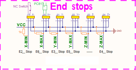
Expansion Header Ex_STOP pinsposted in Duet Hardware and wiring
How am I supposed to wire these up?
using Duet2wifi -
Duet2 WiFi Endstop Voltageposted in Duet Hardware and wiring
Hello, I'd like to clean up the wiring of my machine a little bit and got one of these boards:
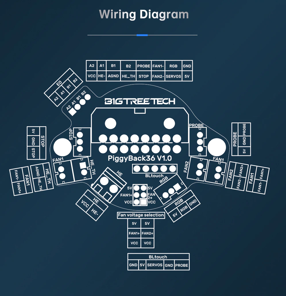
My x_endstop sits on the extruder carriage and would preferably wired trough this board. It uses 5V for the endstop though.
Is it safe to wire Duet2 Wifi endstop to 5V instead of the broken out 3.3V?Or could I do this:
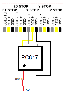
PC817 is optocoupler
?Thanks
-
RE: Single Axis multiple stepper with different steps/mm possible?posted in Firmware installation
Thanks for all the helpful replies.
@o_lampe I would like to stay away from ball screws, as they tend to be rather expensive or a cheap hit/miss. And I'm already very impressed by the results of the belted Z. I did consider other gearing solutions like a worm gear but it is the same pita as acquiring quality ball screws, and a mediocre solution would probably give me more headache than my current counterweights.
I didn't think about the gearing ratio to much, went a little crazy probably should choose less ratio.
How is your ball screw setup geared? belt and pulleys?
I could probably do a 1/10 belted space wise.@jay_s_uk special thanks for the clarifications
@dc42 I didn't. something like this first I could find on aliexpress? Are they in holding position when no power is applied?
-
Single Axis multiple stepper with different steps/mm possible?posted in Firmware installation
Hello, my machine runs triple belted Z axis. This is my current driver mapping and steps/mm.
M584 X0 Y1 Z7:8:9 E3
M92 X80.00 Y80.00 Z80.00 E427.8
My bed does drop when power is cut, currently I use counterweights to avoid this but I'd like to find another solution.
First thing I'd like to try is planetary geared (51/1) nema17 motor. However I'm on a budget and before ordering 3 of them I would prefer to try just one.
I don't think it is possible to assign driver numbers in M92, is there any way to achieve this? -
RE: Triple Z G28/G32 homing errorposted in Firmware installation
Nevermind this, was wrong again, but you got me in the right direction. Thanks for that^^
-
RE: Triple Z G28/G32 homing errorposted in Firmware installation
@jay_s_uk
I just remembered that when I first create files for this machine I selected by mistake coreXZ instead of coreXY in the configuration tool... I already changed that in config.g to corexy but didn't think of all the other files
could there be other corruptions?fixed my homeall.g to:
; homeall.g
; called to home all axes
;
; generated by RepRapFirmware Configuration Tool v3.3.14 on Tue Nov 15 2022 22:25:09 GMT+0100 (Central European Standard Time)
G91                     ; relative positioning
G1 H2 Z5 F6000          ; lift Z relative to current position
G1 H1 X-235 Y-215 F1800 ; move quickly to X or Y endstop and stop there (first pass)
G1 H1 X-235             ; home X axis
G1 H1 Y-215             ; home Y axis
G1 X5 Y5 F6000          ; go back a few mm
G1 H1 X-235 F360        ; move slowly to X axis endstop once more (second pass)
G1 H1 Y-215             ; then move slowly to Y axis endstop
G1 H1 Z-205 F360        ; move Z down stopping at the endstop
G90                     ; absolute positioning
G92 Z0                  ; set Z position to axis minimum (you may want to adjust this)

; Uncomment the following lines to lift Z after probing
;G91                    ; relative positioning
;G1 Z5 F100             ; lift Z relative to current position
;G90                    ; absolute positioning
now G28 does work, but G32 still throws the error
-
RE: Triple Z G28/G32 homing errorposted in Firmware installation
@jay_s_uk
homeall.gG91 ; relative positioning G1 H1 X-235 Z-205 F1800 ; move quickly to X or Z endstop and stop there (first pass) G1 H1 X-235 ; home X axis G1 H1 Z-205 ; home Z axis G1 X5 Z5 F6000 ; go back a few mm G1 H1 X-235 F360 ; move slowly to X axis endstop once more (second pass) G1 H1 Z-205 ; then move slowly to Z axis endstop G1 H2 Z5 F6000 ; lift Z relative to current position G1 H1 Y-215 F1800 ; move Y down stopping at the endstop G90 ; absolute positioning -
Triple Z G28/G32 homing errorposted in Firmware installation
Hello,
I'm having trouble setting up my printer to do auto bed levelling. It is a custom corexy machine using 3 individual Z motors and a bltouch as Zprobe.I can run M28 X, M28 Y and M28 Z individually without a problem.
M28 however throws: ''Error: Failed to enable endstops''bed.g
G28 ; home
G30 P0 X0 Y0 Z-99999 ; probe near a leadscrew front left
G30 P1 X369 Y0 Z-99999 ; probe near a leadscrew front right
G30 P2 X177 Y329 Z-99999 S3 ; probe near a leadscrew rear mid. and calibrate 3 motors
Also I can run:
G30 P0 X0 Y0 Z-99999
G30 P1 X369 Y0 Z-99999
G30 P2 X177 Y329 Z-99999 S3
individually, and it does work as intended
G32 however also throws: ''Error: Failed to enable endstops''
I assume because my bed.g starts with G28config.g
; General preferences
M575 P1 S1 B57600                              ; enable support for PanelDue
G90                                            ; send absolute coordinates...
M83                                            ; ...but relative extruder moves
M550 P"CryXY"                             ; set printer name
M669 K1                                        ; select CoreXY mode

; Network
M552 S1                                        ; enable network
M586 P0 S1                                     ; enable HTTP
M586 P1 S0                                     ; disable FTP
M586 P2 S0                                     ; disable Telnet

; Drives
M569 P0 S0                                     ; X physical drive 0 goes reverse
M569 P1 S1                                     ; Y physical drive 1 goes forwards
M569 P7 S0                                     ; Z physical drive 7 = E4-RampsZ goes reverse
M569 P8 S1                                     ; Z physical drive 8 = E5-RampsY goes forwards
M569 P9 S0                                     ; Z physical drive 9 = E6-RampsX goes reverse
M569 P3 S1                                     ; E physical drive 3 goes forwards
M584 X0 Y1 Z7:8:9 E3                           ; set drive mapping (changed to triple Zyx)
M671 X201.5:444.5:-41.5 Y400.3:-20.6:-20.6 S6   ; level points from CAD at rear mid z, front right y, rear front left x. Snnn max correction move. Fnnn Fudge Factor
M350 X16 Y16 Z16 E16 I1                        ; configure microstepping with interpolation
M92 X80.00 Y80.00 Z80.00 E415.00               ; set steps per mm
M566 X900.00 Y900.00 Z900.00 E120.00           ; set maximum instantaneous speed changes (mm/min)
M203 X6000.00 Y6000.00 Z6000.00 E1200.00       ; set maximum speeds (mm/min)
M201 X500.00 Y500.00 Z200.00 E250.00           ; set accelerations (mm/s^2)
M906 X800 Y800 Z800 E800 I30                   ; set motor currents (mA) and motor idle factor in per cent
M84 S30                                        ; Set idle timeout

; Axis Limits
M208 X-18 Y-3 Z0 S1                               ; set axis minima (max travel X414 Y348 Z???)
M208 X396 Y345 Z200 S0                         ; set axis maxima (my current offset X-18 Y-3)

; Endstops
M574 X1 S1 P"xstop"                            ; configure switch-type (e.g. microswitch) endstop for low end on X via pin xstop
M574 Y1 S1 P"ystop"                            ; configure switch-type (e.g. microswitch) endstop for low end on Y via pin ystop

; Z-Probe
M950 S0 C"exp.heater3"                         ; create servo pin 0 for BLTouch
M558 P9 C"^zprobe.in" H5 F120 T6000 R0.2 A3    ; set Z probe type to bltouch and the dive height + speeds  MUA R A
G31 P500 X24.5 Y4.35 Z2.5                      ; set Z probe trigger value, offset and trigger height
M557 X15:215 Y15:195 S20                       ; define mesh grid DOOOOIT

; Heaters
M308 S0 P"bedtemp" Y"thermistor" T100000 B4138 ; configure sensor 0 as thermistor on pin bedtemp
M950 H0 C"bedheat" T0                          ; create bed heater output on bedheat and map it to sensor 0
M307 H0 B0 S1.00                               ; disable bang-bang mode for the bed heater and set PWM limit
M140 H0                                        ; map heated bed to heater 0
M143 H0 S120                                   ; set temperature limit for heater 0 to 120C
M308 S1 P"e0temp" Y"thermistor" T100000 B4138  ; configure sensor 1 as thermistor on pin e0temp
M950 H1 C"e0heat" T1                           ; create nozzle heater output on e0heat and map it to sensor 1
M307 H1 B0 S1.00                               ; disable bang-bang mode for heater  and set PWM limit
M143 H1 S280                                   ; set temperature limit for heater 1 to 280C

; Fans
M950 F0 C"fan0" Q500                           ; create fan 0 on pin fan0 and set its frequency
M106 P0 S0 H-1                                 ; set fan 0 value. Thermostatic control is turned off
M950 F1 C"fan1" Q500                           ; create fan 1 on pin fan1 and set its frequency
M106 P1 S1 H1 T45                              ; set fan 1 value. Thermostatic control is turned on

; Tools
M563 P0 S"BMG" D0 H1 F0                               ; define tool 0
G10 P0 X0 Y0 Z0                                ; set tool 0 axis offsets
G10 P0 R0 S0                                   ; set initial tool 0 active and standby temperatures to 0C

; Custom settings are not defined
Thanks