Yes its the DWC
Gettings alternate messages - Disconnected and Connection Established.
Now i have removed the multipled system.
The endstop is not able to communicate when a M119 command is sent from the DWC
Yes its the DWC
Gettings alternate messages - Disconnected and Connection Established.
Now i have removed the multipled system.
The endstop is not able to communicate when a M119 command is sent from the DWC
Hi Tony
I am connecting via ethernet
And the vesion of the boards are as follows
DWC : 3.4.5
Duet 3 MB6HC : 3.4.6
Previously i had multiple motion system. Since i was getting an error of M596 COMMAND ERROR.
I currenlty removed this configuration and trying to start with a basic setup.
I was testing the endstop status by sending M119 command. I was able to detect the Z axis, however i was not able to get the X and Y axis endstop.
For better understanding i am pasting my config.g files for reference```
; Configuration file for Duet 3 MB 6HC (firmware version 3.3)
; executed by the firmware on start-up
;
; General preferences
G90 ; send absolute coordinates...
M83 ; ...but relative extruder moves
M550 P"CENIMAT WAAM" ; set printer name
; Network
M551 P"SMARTWAAM" ; set password
M552 P192.168.2.12 S1 ; enable network and set IP address
M553 P255.255.255.0 ; set netmask
M554 P192.168.2.14 ; set gateway
M586 P0 S1 ; enable HTTP
M586 P1 S0 ; disable FTP
M586 P2 S0 ; disable Telnet
; Drives
G4 S2 ; Wait for expansion boards to start
M569 P0.0 S0 ; Main board.Z0 drive (Z1 Motor) 0.0 goes backward
M569 P0.1 S0 ; Main board.Z1 drive (Z2 Motor) 0.1 goes backward
M569 P0.2 S0 ; Main board.Z2 drive (Z3 Motor) 0.2 goes backward
M569 P0.3 S0 ; Main board.Z3 drive (Z4 Motor) 0.3 goes backward
M569 P0.4 S0 ; Main board.Z4 drive (U Feeder Motor) 0.4 goes backward
M569 P1.0 S0 ; Expansion board.X drive (X Motor) 1.0 goes backward
M569 P1.1 S0 ; Expansion board.Y1 drive (Y1 Motor) 1.1 goes backward
M569 P1.2 S0 ; Expansion board.Y2 drive (Y2 Motor) 1.2 goes backward
M584 X1.0 Y1.1:1.2 Z0.0:0.1:0.2:0.3 ; set axes drive mapping, expansion board:X&Y axes,main board:Z axis, main board:U axis (feeder motor 1)
M671 X5:5:545:545 Y80:455:455:80 S5.0 ; leadscrews at Front left, Rear Left, Rear Right and Front right
M350 X16 Y16 Z16 I1 ; configure microstepping with interpolation
M92 X400.00 Y400.00 Z400.00 ; set steps per mm
M566 X300.00 Y300.00 Z180.00 ; set maximum instantaneous speed changes (mm/min)
M203 X3000.00 Y3000.00 Z600.00 ; set maximum speeds (mm/min)
M201 X100.00 Y100.00 Z20.00 ; set accelerations (mm/s^2)
M906 X2520 Y2520 Z2520 I100 ; set motor currents (mA) and motor idle factor in per cent
M84 S3600 ; Set idle timeout
; Axis Limits
M208 X0 Y0 Z0 S1 ; set axis minima
M208 X550 Y460 Z510 S0 ; set axis maxima
; Endstops
M574 X1 S1 P"!1.io0.in" ; configure switch-type (microswitch) endstop for low end on X via pin io0.in via CAN address 1, Expansion board
M574 Y1 S1 P"!1.io1.in+!1.io2.in" ; configure switch-type (microswitch) endstop for low end on Y1 & Y2 via pin io1.in & io2.in via CAN address 1, Expansion board
M574 Z2 S1 P"!io0.in+!io1.in+!io2.in+!io3.in" ; configure switch-type (microswitch) endstop for High end on Z via pin io0.in,io1.in,io2.in,io3.in via Main board
M574 U1 S1 P"0.io7.in" ; simple switch on high end
; Z-Probe
M558 P5 C"!io8.in" H30 F300 T6000 ; enable Z probe sensor endstop io8.in (Main Board) set dive height, probe speed and travel speed
G31 X0 Y0 Z15 ; set or report current probe status
M557 X0:550 Y70:460 S100 ; define mesh grid
; Temperature Sensors
M308 S10 Y"mcu-temp" A"MCU" ; defines sensor 10 as main board MCU temperature sensor
M308 S11 Y"drivers" A"Duet stepper drivers" ; defines sensor 11 as stepper driver temperature sensor
M308 S12 Y"mcu-temp" P"1.dummy" A"3HC MCU" ; defines sensor 12 as expansion board MCU temperature sensor via CAN address 1
M308 S13 Y"drivers" P"1.dummy" A"3HC Steppers" ; defines sensor 13 as expansion board stepper driver temperature sensor via CAN address 1
; weldtorchstae
global weldtorchstate = 0 ; assume initially OFF, change 1 to ON
; Fans
M950 F1 C"out7" Q250 ; Create fan 1 pin OUT_7 (fan output) and set its frequency
M106 P1 S0 H-1 ; Set fan 1 value. Thermostatic control is turned off
M950 F2 C"out8" Q250 ; Create fan 2 pin OUT_8 (fan output) and set its frequency
M106 P2 S0 H-1 ; Set fan 2 value. Thermostatic control is turned off
M950 P3 C"out9" ; Allocate GPIO port 3 to OUT_9, Weld Torch Relay 5V normal relay
; Custom settings are not defined
M950 J1 C"io6.in" ; Configure pin J1 as input and assign input pin "io6.in"
M581 P1 T0 S1 R0 ; Setup Pin 1 when trigger occurs S1 from High to Low State during any time R0 for Emergemcy Push Button, no trigger.g needed
M581 P1 T2 S0 R0 ; Setup Pin 1 when trigger occurs S0 from Low to High State during any time R0 for Emergemcy Push Button, trigger2.g needed
M950 J6 C"!0.io4.in" ; Configure pin J6 as Z Min(Low End) Trigger and assign input pin "io4.in" in Main Board
M581 P6 T6 S1 R0 ; Setup Pin 6 when trigger occurs S1 from NO to NC during any time R0-trigger6.g
M950 J7 C"!0.io5.in" ; Configure pin J7 as Z Min(Low End) Trigger and assign input pin "io.5.in" in Main Board
M581 P7 T7 S1 R0 ; Setup Pin 7 when trigger occurs S1 from NO to NC during any time R0-trigger7.g
; Miscellaneous
M501 ; load saved parameters from non-volatile memory
Hi
I am using a Duet 3D mainboard 6HC and an expansion board 3HC. The 6HC mainboard was replaced with a newly purchased board, while the expansion board is retained the one that was purchased 2023. On powering both the boards i facing frequent disconnection.
Is this something related to the software version of the boards?
Any suggestions please
Thanks dc42
Below is the picture of 22 AWG 2 Core + Shield cable from Amazon. Previously used 24 AWG, hope this 22 AWG wouldnt be a issue.
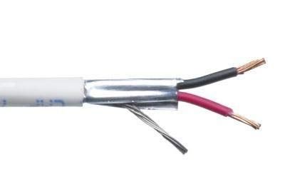
The updated REVISED SHIELD Cable for reference. Is it okay?
GND (Duet) -> Pin 3 (Endstop)
3.3V (Duet) -> Pin (Endstop)
io.in (Duet) -> Pin4 (Endstop)

Thanks Owen
The Video explanation was really helpful in understanding few areas where I was sceptical. So once again thanks very much.
Now as rightly said in the video and explained in this post, In order to have a either a droplet transfer or bridge transfer at any cost the wire plunging to be avoided. In addition, unlike an extruder the wire is feed at an angle to the torch. Finally as Owen rightly pointed out the issues of omnidirectionality is a key issue.
So in order to control these issues one of the way is to play with the WIRE FEED RATE.
Based on the discussions in this post summarized the possible option each with their limitations
G1 X100 E2000 F80
for this code the X axis moves 100 mm at a feedrate of 80mm/min. The WIRE FEEDER extrudes wire at a rate of 80 mm/min for the 2000 mm that is the extruder would be feeding the wire even after the X axis would have stopped. This means that the motion of X axis and the WIRE FEEDER would be coordinated and synchronized at the beginning but not at the end. Is my understanding of this option correct?
Configure as an U axis by multiple motion system
Limitation : A) daemon.g file needs to rename as .PART to update the F parameter and the machine needs to switched
OFF and ON for a certain time like 15-20 mins for the feed rate to update.
B) Not able to vary the WIRE FEEDER FEED RATE in a continuous tool path.
C) Not able to expand for 2nd WIRE FEEDER, only 2 multiple motion systems are possible
Install separate WIRE FEEDER systems and configure as IO through a 5V relay to control the ON/OFF operation through DUET. And the speed can be adjusted by WIRE FEEDER Potentiometer. By this option additional WIRE FEEDERs could be added if required.
Limitation : -
Coordinated and Synchronized movement at the beginning and end are required. In such a scenario option 1 doesn´t suit the purpose. Option 2 has limited flexibility
Any corrections or suggestion would be most welcome plz........
Thanks
For a better understanding, lets consider for example
G1 X100 E2000 F50
As per the above the code the X axis moves 100 mm at a rate of 50 mm/min, the extruder feeds the wire for 2000 mm but at a higher feed rate since the 2000 has to be completed at the same time of X100.
Is my understanding correct?
Hi Owen,
Good to hear from you
Separate Wire feeder is not used for the designed setup.
I have built an custom wire feeder using a stepper motor and configured it as an U axis, hence using multiple motion system
Apologies dc42, hope my explanation is not clear. I will try to explain with the below code which i am currently using for welding.
The below code switches the WELDER ON @ X250 and travels until X360. The line 5 parameter F80 represents the WELD TORCH TRAVEL speed (torch mounted on the X axis bundle). If i try to input the WIRE FEEDER configured as U axis in the same line 5, unable to change the feed rate separately for the WIRE FEEDER, instead only a single feed rate is followed by both the axis i.e., X & U.
M98 P"0:/macros/WELD TORCH OFF+SM"
G1 X250 Y345 Z150 F2000
G1 Z123.10 F2000
M98 P"0:/macros/WELD TORCH ON+SM"
G1 X360 F80
M98 P"0:/macros/WELD TORCH OFF+SM"
G1 Z150 F500
G1 X250 Y345 Z150 F2000
M98 P"0:/macros/WELD TORCH ON+SM"
G1 Z151 F2000
M98 P"0:/macros/WELD TORCH OFF+SM"
Greetings dc42
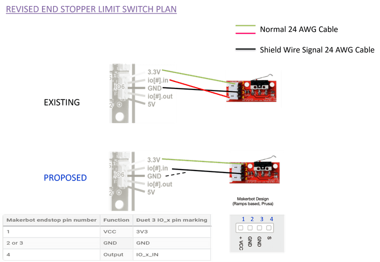
Herewith attached REVISED END STOPPER WIRING LAYOUT.
In the existing plan, the io.in pin of duet is connected to the S pin of the end stopper (PIN:4). In the REVISED Layout this S pin (PIN 4 of end stopper) left blank and from the shielded Wire Signal cable, the shield cable is connected to GND (DUET) and central conductor is connected to io.in pin (DUET).
Is this layout correct. Requesting for any corrections or suggestions plz
Thanks dc42, Its always good to hear from you
I was planning to configure the wire feeder like an extruder. But the WELD TORCH travel speed is much lesser when compared to an WIRE FEEDER.
Lets say for example
Torch Travel Speed : 100 mm/min (Torch is installed on the X axis bundle, so its feed rate is controlled by the X axis motor)
Wire feed rate : 1000 mm/min (Wire feeder configured as U Axis)
So during welding, torch travel speed would be slower and the wire feed rate is significantly higher by almost 10 times. In order to achieve this independent feed rate control the MULTIPLE MOTION SYSTEM was incorporated by integrating the TORCH ON/OFF with WIRE FEEDER ON/OFF.
Yes as you rightly said, torch is SWITCHED OFF during travel moves and so the wire feeder.
If there is any other alternative to achieve this kind of independent feed rate control apart from the multiple motion system. I would like to try it as in the future i may have to add up more wire feeder which would have independent feed rate with the other wire feeders and torch.
Greetings,
I am using a welder On/Off CONTROLLED Via 5V Relay by Duet 6HC Main board. Planning to separate the existing wire feeder (configured as multiple motion system so as to have an independent feed rate/control to the 3 axis motion system) to an SEPERATE WIRE FEEDER SYSTEM.
The current system WELD ON/OFF and WIRE FEEDER ON/OFF is integrated through an daemon.g. On separating the wire feeder the daemon.g may not be required, but would like to retain the current coordinated action/command of the WELDER and WIRE FEEDER.
The Wire Feeder has an TRIGGER CONTROL unit, planning to connect this with a 5V relay to IO Port of the Duet 6HC mainboard and control the On/Off of the feeder through a macro file similar to the the welder operation. Does this idea workout? Is there any other details i have to look on......
Requesting the suggestion/feedback plz....
THANKS
The first Option ¨grounding the metalwork of the machine (if it isn't already) and connecting Duet VIN negative to that ground;¨
The second option ¨using shielded cable t connect the limit switches¨
Finally I was thinking to use a more robust limit switch sensors that is able to withstand these kind WELD EMF interference. Any suggestions on these would be most welcome......
Thanks
Arc was established, torch that was mounted on the X axis stopped moving.
Error message displayed as EXPANSION BOARD ERROR
The X & Y Axis are mounted to the expansion board.
So for a quick check when the X and Z axis limit switch sensors are removed. No such error was seen
Re: Duet 6 HC and 3HC Board Not able to Integrate with WELDER
This message is drafted in relation to a previous post.
Have used a 6HC mainboard and 3HC mainboard for operating a welding machine with multiple motion system.
Using a daemon.g file to change the feed rate of the wire feeder motor.
A simple 5V relay is being used for switching the WELD MACHINE ON/OFF.
; Weld Torch ON
M42 P3 S0 ; turns on the relay
;set WeldTorchState to ON
global.WeldTorchState = 1
; Weld Torch OFF
M42 P3 S1 ; turns off the relay
; set WeldTorchState to OFF
global.WeldTorchState = 0
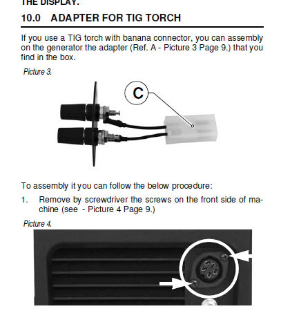
WELDMACHINE : CITOTIG 2200 FORCE
WELD MACHINE CONNECTION TO DUET MAINBOARD 6HC Through connector as shown below via 5V Relay
During the operation of the welder an arc is established but the axis stops moving. Suspecting some kind of EMF interference caused by the weld circuit.
Greetings,
I am uing a 6HC mainboard and 3 HC expansion board to use multiple motion system for a customized weld machine setup.
Created a daemon.g file and interfaced the signals of WELD Torch and a wire feeder stepper motor system.
Tested multiple times for moving the Torch and wire feeder, was working just fine.
Today just tried to change the job file using multiple torch travel speed in a single weld. EX: Total 100 mm, first 33 mm - 100 mm/min travel speed, second 33 mm for 120 mm/min travel speed and remaning length 140 mm/min so on.
So on changing the Job File with the code as follows for (single travel speed), machine is not responding
M98 P"0:/macros/WELD TORCH OFF+SM"
G1 X250 Y345 Z150 F2000
G1 Z123.10 F2000
M98 P"0:/macros/WELD TORCH ON+SM"
G1 X360 F80
M98 P"0:/macros/WELD TORCH OFF+SM"
G1 Z150 F500
G1 X250 Y345 Z150 F2000
M98 P"0:/macros/WELD TORCH ON+SM"
G1 Z151 F2000
M98 P"0:/macros/WELD TORCH OFF+SM"
Any suggestions on such kind of machine behaviour would be appreciated.
Hi Everyone,
I have built a Custom CNC using 6HC mainboard and a 3HC Expansion board. Integrated with a welding machine controlling through a 5V normal relay. During the tryouts without the weld machine ON is good i.e., that is the torch movement.
However when tried integrating the WELDER with the CNC the X and Y Axis doesnt move only the welder switches ON.
And observed that the X and Y Axis stepper motors are able to rotate by hand. I am suspecting some kind EMF Interference.
Requesting the help of Forum members on understading and solve this issue
Thanks for the feedback
Removed the M106 code and changed the Q value to 3000.
Using the macros with M42 CODE now and increased the S parameter value to 255.
The issue persists.
Hi Everyone,
This thread is in continuation with an earlier thread https://forum.duet3d.com/topic/34670/connecting-a-bldc-controller-to-duet-mainboard-6hc.
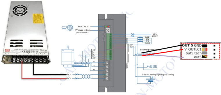
Completed the Wiring and configuring a BLDC motor with a driver. Facing a issue on ON and OFF the motor operation through duet. Wiring and configuration files are shown below. Not sure of what the problem is? Any inputs and suggestions would be much appreciated
The motor operates well when controlled though a BLD750 driver
config.g
;fans
M950 P5 C¨out5¨ Q250  ; Allocate GPIO port 5 to OUT_5 (fan output), 250Hz
M106 P5 S255
DC Motor ON @50% Speed
M42 P5 S0.5     ; Set 50% PWM on GPIO port 5
DC Motor OFF
M42 P5 S0     ; Set 50% PWM on GPIO port 5