• Tags
  • Documentation
  • Order
  • Register
  • Login
Duet3D Logo Duet3D
  • Tags
  • Documentation
  • Order
  • Register
  • Login
  1. Home
  2. Schild0r
  3. Posts
  • Profile
  • Following 0
  • Followers 0
  • Topics 13
  • Posts 53
  • Best 8
  • Controversial 0
  • Groups 0

Posts made by Schild0r

  • RE: slicer printing time vs real printing time

    @Phaedrux said in slicer printing time vs real printing time:

    @Schild0r Can you try simulating the file and see what the simulated time ends up being?

    Do you have a speed or accel limit set lower in your config.g than it's trying to use in the sliced file?

    The simulation time compared to the slicer estimated time or to the actual print time?
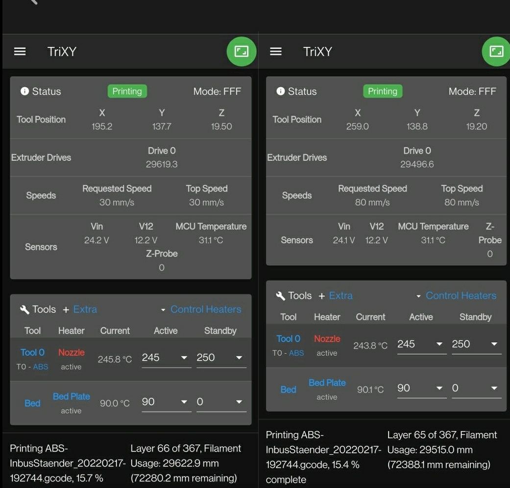
    According to prusaslicer the estimated print time is 6:41
    Simulation says it is 7:34
    I am actually not sure anymore about the actual print time and don't think I could look it up anymore unless I print it again. I might need to work on some sort of logfile generation...

    My config.g contains these lines in regards to speed, acceleration and jerk

    M566 X600.00 Y600.00 Z60.00 E300.00                        ; set maximum instantaneous speed changes (mm/min)
    M203 X12000.00 Y12000.00 Z600.00 E3000.00                  ; set maximum speeds (mm/min)
    M201 X7000.00 Y7000.00 Z20.00 E3000.00                     ; set accelerations (mm/s^2) 
    M204 P5000.00 T7000.00                                     ; set printing and travel accelerations
    ...
    M593 P"MZV" F36.2                                          ; use MZV input shaping to cancel ringing at 36.2Hz
    

    My prusaslicer config looks like this
    f7a27788-c866-4250-998d-59f30f76b86e-image.png
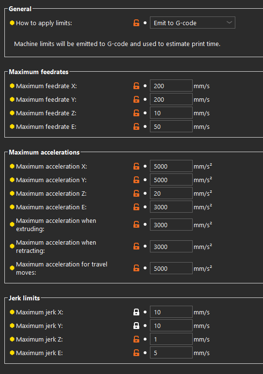
    The travel accel is mismatching my config but since it is emitted to g-code this should not really matter
    G-code and config.g is also attached if you want to simulate yourself.
    a802e68d-cac1-4383-9455-10e8a97bbba4-PET-Laptopstand_20240803-005116.gcode
    565a33ab-fb74-4946-a4ca-c5689ddfdebe-config.g


    @dc42 said in slicer printing time vs real printing time:

    @Schild0r one of the reasons for the discrepancy may be that by default RRF only uses jerk when it is necessary to avoid slowing down (mostly through curves) whereas Marlin-based firmwares use it all the time, because the motion algorithms they use can't cope with acceleration from zero speed or deceleration to zero speed.

    You can get RRF to partially emulate that behavior using the J1 option of M566.

    Over a year ago one of our users submitted a PR to PrusaSlicer to account for this when using RRF and estimating print times, but it wasn't merged.

    hm that might of course explain part of it.
    I tried the simulation with the P1 parameter and also with J1 (was that a typo since I dont see it mentioned in the gcode reference document?) but both made no difference to simulated print times (expected?)
    I would of course like it better if Prusaslicer would actually implement the PR since there is already the gcode flavor selection so why not... any chance that this will be done at some point nevertheless?

    On that note: do you know how prusaslicer handles firmware retraction in regards to print time calculation?
    The retraction parameters will be greyed out when FW retraction is enabled so I assume it might just ignore it?
    I created a feature request to leave the parameters active and use them for print time calculation. Let's see if this gets any attention.

    posted in General Discussion
    undefined
    Schild0r
    2 Aug 2024, 23:12
  • RE: slicer printing time vs real printing time

    @Phaedrux has anything been done in the firmware regarding the discrepancy between slicer predicted and actual print times?
    I am using the current version of Prusaslicer and RRF 3.5.1 and still see a significant difference.
    Prusaslicer will predict something like 6hrs but the print will actually take more like 8hrs.

    • The jerks, accelerations and feedrates are also set to "Emit to G-code" in prusaslicer and not only used for the time estimation so I would think the predicted print times are as accurate as they can get.
    • I do use FW retraction but in the above discussion, this was found to be kind of unrelated
    • I also use input shaping but I would not expect that to make such a significant difference of adding 30% print time

    I can also repeat some tests from above on my machine and post the results in this thread or a new one, but if you already know where the discrepancy might be coming from as you alluded to in the last comment, I am not sure if this would help anything.
    If there are some configuration "errors" that are known to cause such a discrepancy, any hints would be appreciated.

    posted in General Discussion
    undefined
    Schild0r
    1 Aug 2024, 09:32
  • Ignoring electronics cooling fan for M81 S1

    Hey,
    What would be the best or most elegant way to ignore thermostatically controlled electronics cooling fans for deferred power down (M81 S1).
    I'd like to only wait for the thermostatic fans that are assigned to heaters that are assigned to tools to settle. On hot days the electronics cooling fans will rarely turn off.

    Maybe an M81 S2 command could be implemented for that (?)

    Thanks for suggestions.

    posted in Gcode meta commands
    undefined
    Schild0r
    14 Aug 2022, 14:24
  • RE: Filament runout and autoload sensor questions (Prusa MK3S logic)

    Well at least I found an answer to my last question:
    Says right in the documentation

    ^ : (string,string)->string : String concatenation

    In my defense I am not an english native and had never heard the word concatenation before so I just read over it (multiple times).

    So line 8 is now M98 P{"0:/filaments/"^move.extruders[0].filament^"/unload.g"}

    However maybe someone could still tell me if raising the event in the trigger file to act as filament runout is bad or completely fine.

    posted in Gcode meta commands
    undefined
    Schild0r
    6 Jul 2022, 18:01
  • Filament runout and autoload sensor questions (Prusa MK3S logic)

    Hey there,

    I am using an Orbiter 2.0 at the moment with the filament sensor addon.

    I want to use the runout sensor (just a steel ball pressing down a button when filament is present) for both filament runout detection and filament insertion detection but I have run into a few problems:

    1. When I configure a runout sensor using M591 D0 P2 C"^21.io1.in" S1 it should only trigger during prints (S1), however it appears to me that it always triggers, even when no print is running.

    2. If I configure the sensor as a filament runout sensor using M591 D0 P2 C"^21.io1.in" S1 I cannot assign another trigger to it using e.g. M581 P2 T2 S0 so instead I assign two triggers to the same input on different edges:

    M950 J2 C"^21.io1.in"  ; create input 2 on TB1LC io1, pullup enabled
    M581 P2 T2 S0          ; trigger trigger2.g (filament autoload script) when input 2 is falling
    M581 P2 T4 S1 R1       ; trigger trigger4.g (filament runout script) when input 2 is rising during a print
    

    I guess this makes sense but now I am wondering if my trigger4.g file should simply contain a macro call M98 P"filament-error.g" or invoke the actual event with M957 E"filament-error" D0. I think M957 was only designed for debugging purposes but I don't see why I could not use it this way(?)

    1. A filament error does not clear the filament designation from an extruder automatically, which also makes sense and is usefull for autoloading. Lets say I want to use autoloading after a filament runout during a print: I just insert the filament and since there is still the filament assigned to the extruder, the printer would already know which load.g file to use. Unfortunately since there is already filament loaded, one cannot run another load.g even if it is for the same filament. This is my autoloading script, maybe someone can help me what to put in line 8:
    G4 P500                 ; wait 500ms to fully insert filament past the sensor
    M302 S1                 ; temporarily allow cold extrusion
    G1 E5 F600              ; Feed 5mm of filament at 10mm/s into extruder gears
    G1 E45 F3000            ; Feed 45mm of filament at 50mm/s
    M302 P0                 ; Forbid cold extrusion after grabbing filament
    if move.extruders[0].filament != ""
      echo "autoloading", move.extruders[0].filament
      -----> M701 S{move.extruders[0].filament} ;THIS DOES NOT WORK
    else
      echo "grabbing new filament"
      M291 R"Filament autoload" P"No filament assigned to this extruder, run loading sequence for newly inserted filament" S2
    

    Maybe something along the lines of M98 P"0:/filaments/{move.extruders[0].filament}/load.g" would work, but I have not figured out yet, how to properly include a variable into a path called by a Gcode (would be usefull for many applications).
    Another way would be to store the filament name in a variable, then somehow clear the filament designation from the extruder and then run M701. But I also don't know how one would clear the filament designation with code...

    Thanks very much in advance for any hints.

    posted in Gcode meta commands
    undefined
    Schild0r
    4 Jul 2022, 21:02
  • RE: slowing down a non-powered stepper motor

    I considered doing the same thing for my corexy but it turned out the heavy bed didn't fall so I didn't do it in the end. Although I would still like to share my thoughts.
    As already pointed out you could also use a geared stepper to achieve the same thing and this is also on my list for my delta because it always drops to some degree depending on the effector displacement.
    If you are using 0.9 degree steppers, changing over to 1.8 degree can also make a difference.

    But if you still want to go the relay way which I considered doing, you may want to get change-over relays and connected them in a way that in default state (i.e. not triggered) the coils of the steppers are being shorted. And when you turn on the power the relays would then trigger and change over and thus connect the steppers to the drivers. However you would need to make sure that the drivers are not powered when connecting/disconnecting the drivers. This can be done in config but a hardware measure would of course be safer to prevent damaging the drivers.
    I don't think you would need a resistor bc the coils will act as resistors themselves if you short them due to Lenz' law when the motor is turned by an external force (the dropping bed). But do mind that this would probably only slow down the dropping of the bed because the breaking force is proportional to the speed the motor is being turned. So when the bed doesn't drop, there is no breaking, so the bed will drop, so there will be breaking, so the bed won't drop, so there won't be breaking again, and so on...

    Although I'd really like to see and validate this in the real world, I don't have the budget to just buy the equipment for testing this (without tearing my printer apart). So if this is also your concern, you might just want to have a look for steppers with a built in magnetic/mechanical break plus the relays needed for switching these. These will stop your bed from dropping in any case.

    posted in Duet Hardware and wiring
    undefined
    Schild0r
    26 Apr 2022, 21:45
  • RE: Makro with variables

    @suntoxx it is in the dashboard right below the name of the tool. There should be a button "load filament" and if you click it, it should give you a selection of all the filaments you have created in the firmware.

    So not in the left toolbar but where you would change your tool temperature manually at any time

    Screenshot_20220425-190918__01__01.jpg

    For me it says PLA because it is currently loaded.
    You can also load/unload filaments via gcodes M701 S"filamentname" and M702 and it will update this in DWC as well

    posted in Using Duet Controllers
    undefined
    Schild0r
    25 Apr 2022, 17:06
  • RE: Makro with variables

    @engikeneer said in Makro with variables:

    @suntoxx you select the filament that you have loaded with a dropdown in DWC. That way it is not at all embedded in the gcode file s9 you can use the same file for multiple different filaments

    ...the same * Slicer Filament Setting * for multiple different filaments.

    As long as you set everything (temperatures, fan speeds, offsets,...) in the RRF filament config. You only need to call M703 for that to apply (regardless of the filament that is being loaded)

    @sunToxx you can edit a comment btw 😉

    posted in Using Duet Controllers
    undefined
    Schild0r
    25 Apr 2022, 15:52
  • RE: Makro with variables

    @suntoxx said in Makro with variables:

    Isn't that a bit too little? I haven't tried that many filaments yet, so I do not know for sure. But is the optimal offset for all PLAs the same? Regular PLA, matte, silk, PLA that prints at 195°C and PLA that prints at 230°?

    I am using one single z offset globaly and this works fine for me... but as engikeneer said, you could just create a filament profile for every roll of filament you buy.

    @suntoxx said in Makro with variables:

    I think a macro would be more comfortable. If I change an offset value for a material, I could do so in one central place and it affacts all the profiles i want and in all slicers. Plus it would also affect already compiled .gcode files, as long as they already call for that macro. At least in theory, that looks good to me.
    What's the best way to do this?

    Just put the offset (whether it is babystepping or just the trigger offset of your probe/endstop) into the config file of each filament. As long as you then call M703 somewhere in your start gcode, the firmware will always run the config file of the filament that (it thinks) is loaded.

    e.G. That way you could also put your printing temperatures in the config file of the filament and just use a single "default" filament in your slicer with generic temperature values. Then when your print starts and calls M703, the filament config with your offset and temperatures (and PID tunes and fan curves and and pressure advance tunes .etc for that filament) will be loaded.

    posted in Using Duet Controllers
    undefined
    Schild0r
    25 Apr 2022, 15:04
  • RE: Makro with variables

    @suntoxx I am not 100% sure if I understood everything correctly but you could just use the filament logic of RRF to set for example z offsets on a per filament basis in the config.g file of the respective filament (see filaments) and then put M703 in your start gcode before homing

    posted in Using Duet Controllers
    undefined
    Schild0r
    24 Apr 2022, 15:59
  • RE: Object cancellation: cancel global features

    @dc42 said in Object cancellation: cancel global features:

    Would it really make sense to cancel all non-object items at once?

    No of course not all at once, this is why I thought it was maybe possible to count and list non-object items the same way as object items so there would for example the following list

    Object 0: "cube"
    Object 1: "cylinder"
    (non) object -1: purge towers, etc. Everything that the slicer gemerates and does not label as object
    (non) object -2 to -99: e.g. custom gcode sequences that are explicitly labeled via M486 S(-2 to - 99) that the user may want to leave out at some point, and that are not printing moves. The negative numbers only make sure that these custom features can be used regardless of the number of printing objects (for which the slicer/firmware would automatically generate only positive numbers).

    You could of course also label these custom features with M486 S999999 or so because you are realistically not printing a million objects but I am not sure if there would be some implications for that (like the requirement for continuous numbers so the firmware would create "null" placeholders for everything between the last object number that is actually in the gcode and 999999) EDIT: this seems to be the case but only up to 40 objects

    posted in Using Duet Controllers
    undefined
    Schild0r
    24 Apr 2022, 14:42
  • Object cancellation: cancel global features

    I've been looking into object cancellation lately and as of now everything is working as expected even with the standard labels prusaslicer puts in.
    With PS 2.4 you could even use the built in "find and replace" function to put in actual M486 commands where the object numbers (for RRF) would then match the IDs prusaslicer puts in but I haven't figured that out yet.
    However I was wondering why RRF doesn't have the capability to somehow recognize M486 commands with a negative S parameter (intended for purge towers etc) as global features and list them accordingly for example in the object model browser.

    My use case would be pretty gimmicky but it would be nice to have anyway:
    I have a lightbar as status indicator on my printer that gets updated like a progress bar in every layer change. I wanted to add M486 S-99 before the updating sequence in the layer change gcode to then be able to cancel the status bar updates and turn the lightbar of during a print (without it being lit up and updated again in the next layer again).
    However it appears that negative S parameters of M486 will just be ignored or assigned to no object instead of counting them as well.

    Do i just have to assign the status led update to Objectnumber 999999 so that it won't interfere with possible real objects? Or is there a more elegant way?

    Also is there a plugin and/or paneldue interface in the works with which we could interactively see all objects in a list and cancel them?

    posted in Using Duet Controllers
    undefined
    Schild0r
    24 Apr 2022, 09:16
  • RE: checking STATUS

    When your printer is running tfree.g it is not idle but busy (with running the tfree.g macro). Had the same problem when writing my power toggle macro.

    Haven't found an elegant solution to this though... Instead I had to query if the printer is 'busy' but that all heaters are off and so on. If someone knows a way to query the state the printer had before the macro was triggered, please tag me 😉

    posted in General Discussion
    undefined
    Schild0r
    22 Apr 2022, 06:48
  • RE: New Input Shaping plugin v3.4.1-b1

    I noticed just today, that this plugin existed. Must have been two days before release or so that I wrote a macro myself for doing this. (see below)

    Turns out I basically hit bullseye by accident with my shaper settings after running my macro and now comparing the results with the plugin, just because I did not know that MZV would dampen two frequency amplitudes and the second one did luckily coincide perfectly with the amplitude of my x-axis

    But the user Interface of the plugin is very good especially the merged frequency analyses of multiple axis and the damping curves preview for the shapers.
    Only thing I would like to add though are inputs for the acceleration and speed at which the accelerometer data is collected.
    Just a little QOL thing with e.g. a tickbox for "use maximum speeds and accelerations from current config" and if you untick it, you can enter your own values so that they are set before starting the sequence automatically instead of the user having to enter them manually before going to the plugin.
    Oh and returning the printhead back to the center position after the last move would not trigger my OCD 😂

    Also a little sidenote if a dev reads this:
    We now have Height Map in the Control tab
    The Accelerometer Viewer in Machine Specific under the Settings tab
    and the Input Shaping Plugin under the Plugins tab
    One could also debate about the G-Code Viewer (I personally like it under the Job tab) but at least the above three (and maybe even the Object Model browser) are pretty similar and thus should be under the same tab IMO.
    Please feel free to discuss my opinion though.

    the macro if anyone is interested:

    var origXAccel = move.axes[0].acceleration
    var origYAccel = move.axes[1].acceleration
    var feedrate = move.axes[0].speed
    
    if exists(param.F)
    	set var.feedrate = {param.F}
    	echo "speed for accelerometer data collection:", {var.feedrate/60}, "mm/s"
    else
    	echo "param.F not provided, instead maximum speed (X) is used for accelerometer data collection:", {var.feedrate/60}, "mm/s"
    
    G28
    G1 X{move.axes[0].max/2} Y{move.axes[1].max/2} F9000
    
    if exists(param.A)
    	echo "setting X and Y acceleration to", {param.A}, "mm/s^2"
    	M201 X{param.A} Y{param.A}
    	M201
    else
    	echo "param.A not provided, using current accelerations X:", {var.origXAccel}, "mm/s^2, Y:", {var.origXAccel}, "mm/s^2"
    
    echo "collecting acceleration data for X-Axis"
    G91 ; relative positioning
    G1 X-50 F9000
    G4 S2 
    M956 P21.0 S1000 A1 F"inputShapingX.csv"
    G1 X100 F{var.feedrate} 
    G4 S2
    
    echo "collecting acceleration data for Y-Axis"
    G1 X-50 Y-50 F9000
    G4 S2 
    M956 P21.0 S1000 A1 F"inputShapingY.csv"
    G1 Y100 F{var.feedrate} 
    G4 S2
    G1 Y-50 F9000
    G90 ; absolute positioning
    
    if exists(param.A)
    	echo "reverting changes in acceleration"
    	M201 X{var.origXAccel} Y{var.origYAccel}
    	M201
    
    posted in Plugins for DWC and DSF
    undefined
    Schild0r
    18 Apr 2022, 15:29
  • RE: DWC on mobile jumping/flickering due to Voltage fluctuations

    @phaedrux Oneplus 8 Pro (doesn't matter if I run it at FHD or 4k) on chrome and brave. DWC 3.3.0

    posted in Duet Web Control
    undefined
    Schild0r
    19 Feb 2022, 13:50
  • DWC on mobile jumping/flickering due to Voltage fluctuations

    Heyho,
    I got an issue with DWC on mobile where the whole page below the "sensors" info panel will jump up or down one line because with Vin at 24.1V the whole topic will fit into 3 lines but whenever Vin changes to 24.2 or 24.0 (0 and 2 are wider characters than 1) the last item (in my case z-probe) will be pushed into the nex line. Here is two screenshots side by side:
    Screenshot_20220217-232036__01__01.jpg
    With voltage fluctuations or the Vin sitting at about 24.15V this is quite annoying and leads to the page jumping multiple times a second which makes it hard to hit a certain button and not accidentally tap below or above it.
    I was wondering if I am the only one experiencing this and whether this is dependent on the screen resolution or if there would be a way to fix it...
    For me it would probably be enough to change the label "MCU Temperature" to "MCU Temp." but if this breaks things for other people with different screen resolutions that wouldn't be a proper fix.

    posted in Duet Web Control
    undefined
    Schild0r
    17 Feb 2022, 22:33
  • RE: Save stealthChop2 auto tune parameters to read on startup

    @dc42 thanks, somehow i missed that there is an M569.2 command. Now I only need to find out which register it is I am looking for. Guess I'll have to go reading through them one by one til I find something familiar...
    Driver register 0x70 (R112) is at 0x00000000 althought the datasheet says this would be the one I am looking for and M569 P0.0 reports that there are non zero values

    posted in Tuning and tweaking
    undefined
    Schild0r
    19 Jan 2022, 21:31
  • Save stealthChop2 auto tune parameters to read on startup

    I just got StealthChop2 working on my Duet 3 with this macro which includes the automatic tuning sequence on X and Y

    ; enable_stealthChop2.g
    ; sets stealthChop2 parameters and uses a homing sequence for the driver to automatically tune its current regulation parameters
    ; default stealthChop2 parameters (for standstill noise reduction) are tpwmthrs(V)=2000, thigh(H)=200, tcoolthrs(T)=2000
    ; stealthChop2 tested (under no printing conditions) flawlessly up to 150mm/s (higher speeds not yet tested)
     
    ;homing x and y in default mode of operation
    G91                                                               ; relative positioning
    ;G1 H2 Z5 F240                                                    ; lift z 5mm relative to current position ;enable when using this macro in conjunction with z homing
    G1 H1 X{-move.axes[0].max-5} Y{move.axes[1].max+5} F3600          ; move quickly to x or y endstop and stop there
    G1 H1 X{-move.axes[0].max-5}                                      ; home x
    G1 H1 Y{move.axes[1].max+5}                                       ; home y
    G1 X5 Y-5                                                         ; back up 5mm
    G1 H1 X{-move.axes[0].max-5} F360                                 ; home x slowly (second pass)
    G1 H1 Y{move.axes[1].max+5}                                       ; home y slowly (second pass)
    M400                                                              ; wait for moves to finish
     
    ;enable stealthChop2 and tuning step AT#1
    M18 X Y                                                           ; disable x and y steppers
    M569 P0.0 D3 V0 H0                                                ; enable stealthchop and set tpwmthrs and thigh for X
    M569 P0.1 D3 V0 H0                                                ; enable stealthchop and set tpwmthrs and thigh for Y
    M915 P0.0 T0                                                      ; set tcoolthrs for X
    M915 P0.1 T0                                                      ; set tcoolthrs for Y
    M17 X Y                                                           ; enable x and y steppers with full run current
    G4 P150                                                           ; pause for 150ms to satisfy AT1 condition
    G92 X{move.axes[0].min} Y{move.axes[1].max}                       ; set home positions again after position loss due to M18
    G90                                                               ; absolute positioning
     
    ;tuning step AT#2
    G1 Y{move.axes[1].max/2} F6000                                    ; tuning move at "typical speed" that is a straight line in order to move both steppers (CoreXY) significantly i.e. >400 full steps @ 60-300RPM ->F(150RPM*beltpitch*pulleyteeth)
    G1 X{move.axes[0].max/2}                                          ; move to bed center
    

    (stealthChop2 runs very stable up to 150mm and beyond, thus I set the H V and T parameter to 0 so that the drivers will exclusively run in stealthChop2)

    After running the macro the values of pwmOfsAuto and pwmGradAuto differ from the values they have on startup. In the TMC5160 datasheet says that these values could be saved to pwmOfs and pwmGrad in the driver register as starting points for the automatic tuning process when starting up the machine. I figure with these values set I could set all the stealthChop2 parameters in the config and spare running my macro from above...
    Is there a way we can do that? Maybe with the M569 C parameter? If so what would the C value be exactly?

    If this helps here is a table of the register these values reside in:
    Screenshot_20220119-190601.jpg

    posted in Tuning and tweaking
    undefined
    Schild0r
    19 Jan 2022, 18:17
  • RE: How to rehook Toolboard 1LC?

    @dc42 thanks this works. I guess only rerunning an excerpt from config.g with the commands that concern the Toolboard would work too(?)

    EDITEDIT:

    I just noticed when I rerun the config after I re-apply 24 V I get the following response

    HTTP is enabled on port 80
    FTP is disabled
    TELNET is disabled
    Warning: Board 21 does not have input handle 1000
    Warning: Board 21 does not have input handle 3000
    

    Never got the Network echos before I installed the Toolboard but thats fine I guess, I now always get them on startup too (maybe because of the additional pause in the config for the CAN expansion board).
    However what is it with the input handle? When I rerun the config without cutting and re-applying 24V I don't get these warnings.

    posted in Duet Hardware and wiring
    undefined
    Schild0r
    8 Jan 2022, 10:56
  • How to rehook Toolboard 1LC?

    Hello everyone,
    I am in the process of putting my Toolboard into operation but I am running into an issue here or maybe I am just overlooking something.
    I have two PSUs one 24V one for everything and one 5V one for standby power that also keeps the Duet3 running.
    I can switch the 24V via IO of the duet but when I switch it off the Toolboard obviously looses power and CAN connection (I set it to CAN address 21). DWC will then show heater1 as offline and temp1 as 2000°C (PT1000) which is expected.
    However when I switch the 24V PSU on again it will stay "offline" and at 2000°C. Sending M999 B21 doesn't help.
    CAN does seem to be connected tho because when I send M122 B21 I get a response:

    M122 B21
    Diagnostics for board 21:
    Duet TOOL1LC firmware version 3.3 (2021-06-15 16:12:58)
    Bootloader ID: SAMC21 bootloader version 2.3 (2021-01-26b1)
    Never used RAM 3064, free system stack 2789 words
    Tasks: Move(notifyWait,0.0%,153) HEAT(delaying,0.0%,117) CanAsync(notifyWait,0.0%,65) CanRecv(notifyWait,0.0%,76) CanClock(notifyWait,0.0%,65) ACCEL(notifyWait,0.0%,61) TMC(notifyWait,2.8%,57) MAIN(running,92.2%,436) IDLE(ready,0.0%,27) AIN(delaying,4.9%,142), total 100.0%
    Last reset 00:00:30 ago, cause: software
    Last software reset time unknown, reason: AssertionFailed, available RAM 3392, slot 2
    Software reset code 0x0120 ICSR 0x00000000 SP 0x2000415c Task  Freestk 129 bad marker
    Stack: 00000544 00022ffc 00019b65 20003134 00016cff 20003134 000163d1 20000ed0 00000000 00000001 00008275 344477d8 22ac71dd 200071f4 1434000c 30000f51 200917cf 051233b9 882a257e 00531afc ac899f85 246271dc 670471c9 60040fd2 2a0083ed 688175d8 aac819d7
    Driver 0: position 0, 80.0 steps/mm, standstill, SG min/max 0/0, read errors 0, write errors 1, ifcnt 19, reads 15233, writes 9, timeouts 0, DMA errors 0, steps req 0 done 0
    Moves scheduled 0, completed 0, in progress 0, hiccups 0, step errors 0, maxPrep 0, maxOverdue 0, maxInc 0, mcErrs 0, gcmErrs 0
    Peak sync jitter 0/4, peak Rx sync delay 507, resyncs 0/0, no step interrupt scheduled
    VIN: 24.5V
    MCU temperature: min 30.8C, current 31.6C, max 31.6C
    Ticks since heat task active 14, ADC conversions started 30508, completed 30507, timed out 0, errs 0
    Last sensors broadcast 0x00000000 found 0 18 ticks ago, loop time 0
    CAN messages queued 29, send timeouts 0, received 283, lost 0, free buffers 37, min 37, error reg 0
    dup 0, oos 0/0/0/0, bm 0, wbm 0, rxMotionDelay 0
    Accelerometer detected: yes, status: 00
    I2C bus errors 0, naks 0, other errors 0
    

    Only thing that looks odd to me is that the esteps are also reseting to 80 instead of the 562 I set them to in the config.

    So how can I rehook my Toolboard properly after only it looses and regains power without restarting the whole machine?
    (also do I need to unhook it before cutting power? If so, how?)

    posted in Duet Hardware and wiring
    Schild0rundefined
    Schild0r
    8 Jan 2022, 10:00
Unless otherwise noted, all forum content is licensed under CC-BY-SA