@dc42 I just tried it.
This did not make a difference for me.
The firmware was correctly installed and the name displayed on the Paneldue corresponds to the one you provided.
Best posts made by Shoki
-
RE: Duet 2 Ethernet disconnect when printing and paneldue connectedposted in PanelDue
-
RE: Tool and probe offset to variabneposted in Gcode meta commands
@T3P3Tony Thanks a lot ! I missed them when I read through the object model I don't know why.
-
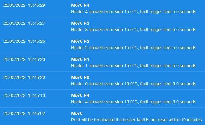
RE: Heater fault not detectedposted in Using Duet Controllers
@gloomyandy @infiniteloop @jay_s_uk
I believe you were right and the problem was indeed a wiring problem.
With the printer on, I just jiggled the connector on the duet and the readings went off the charts. I believe it's just bad crimps and I will re-do these and it should fix the problem. I checked the cable themselves and they look fine.However, this still does not explain why the heater fault was not triggered at 8:46 with the huge temperature drop.
@infiniteloop Yes I made a typo, I typed "M570 H4" (which is my bed heater).
Since I haven't changed this in my config.g, it's the default value for all the heaters.
And this is my config.g :
; Configuration file for Duet WiFi / Ethernet running RRF3 on E3D Tool Changer ; executed by the firmware on start-up ;######################## ; General preferences ;######################## M111 S0 ; Debugging off G21 ; Work in millimetres G90 ; Send absolute coordinates... M83 ; ...but relative extruder moves M555 P2 ; Set firmware compatibility to look like Marlin M667 S1 ; Select CoreXY mode ;######################## ; Network ;######################## M550 P"ToolChanger" ; Set machine name "part of config.g deleted for obvious reasons" ;######################## ; Drive ;######################## ;Drive directions M569 P0 S0 ; Drive 0 (X) M569 P1 S0 ; Drive 1 (Y) M569 P2 S1 ; Drive 2 (Z) M569 P3 S0 ; Drive 3 (C) M569 P4 S0 ; Drive 4 (E0) M569 P5 S0 ; Drive 5 (E3) M569 P6 S0 ; Drive 6 (E2) M569 P7 S0 ; Drive 7 (E1) M569 P8 S0 ; Drive 8 UNUSED M569 P9 S0 ; Drive 9 UNUSED ;Drive mapping and control M584 X0 Y1 Z2 C3 E4:7:6:5 ; Stepper motor connection points, see C:\Users\YN14386\Documents\Documentation\Toolchanger for wiring diagram M208 X-35:328.5 Y-49:243 Z0:300 C-45:360 ; Set axis maxima & minima M92 X100 Y100 Z800 C91.022 E392:392:392:392 ; Set steps per mm assuming x16 microstepping M350 X16 Y16 Z16 I1 ; Configure microstepping with interpolation for the extruders M350 E16:16:16:16 I1 ; Configure microstepping with interpolation for the XYZ movements M350 C16 I10 ; Configure microstepping without interpolation for the coupler ;Drive speeds and acceleration M203 X35000 Y35000 Z1200 C5000 E5000:5000:5000:5000 ; Set maximum speeds (mm/min) M201 X2000 Y2000 Z400 C500 E2500:2500:2500:2500 ; Set maximum accelerations (mm/s^2) was X6000 Y6000 M566 X400 Y400 Z8 C2 E400:400:400:400 ; Set the jerk : maximum instantaneous speed changes (mm/min) ; Motor current M906 X1800 Y1800 Z1330 I30 ; Idle motion motors to 30% M906 E1000:1000:1000:1000 C500 I10 ; Idle extruder and cooupler motors to 10% ;######################## ; Endstops ;######################## ;X and Y axis M574 X1 Y1 S3 ; Set X / Y endstop stall detection M915 X Y S3 F0 H400 R1 ; Stall Detection for the X and Y Axes ; ; Coupler Axis M574 C0 Z0 ; No C Z endstop, it just crashes ;Z axis M558 P8 C"zstop" H3 F360 I0 T20000 ; Set Z probe type to switch, the axes for which it is used and the dive height + speeds G31 P200 X0 Y0 Z0 ; Set Z probe trigger value, offset and trigger height M557 X10:290 Y20:180 S40 ; Define mesh grid ;M376 H15 ; bed compensation taper ;######################## ; Heaters ;######################## ;see C:\Users\YN14386\Documents\Documentation\Toolchanger\*** for connection points names ;Tool 0 M308 S0 P"e1temp" Y"thermistor" A"Heater 0" T100000 B4725 C7.06e-8 ; Set thermistor number (S), connection point (P), name (A) and parameters (YTBC) M950 H0 C"e1heat" T0 ; Set heater number (H) and connection point (C) M143 H0 S285 ; Set temperature limit for heater to 285C ;Tool 1 M308 S1 P"duex.e2temp" Y"thermistor" A"Heater 1" T100000 B4725 C7.06e-8 ; Set thermistor number (S), connection point (P), name (A) and parameters (YTBC) M950 H1 C"duex.e2heat" T1 ; Set heater number (H) and connection point (C) M143 H1 S285 ; Set temperature limit for heater to 285C ;Tool 2 M308 S2 P"duex.e3temp" Y"thermistor" A"Heater 2" T100000 B4725 C7.06e-8 ; Set thermistor number (S), connection point (P), name (A) and parameters (YTBC) M950 H2 C"duex.e3heat" T2 ; Set heater number (H) and connection point (C) M143 H2 S285 ; Set temperature limit for heater to 285C ;Tool 3 M308 S3 P"duex.e4temp" Y"thermistor" A"Heater 3" T100000 B4725 C7.06e-8 ; Set thermistor number (S), connection point (P), name (A) and parameters (YTBC) M950 H3 C"duex.e4heat" T3 ; Set heater number (H) and connection point (C) M143 H3 S285 ; Set temperature limit for heater to 285C ;Heated bed M308 S4 P"bedtemp" Y"thermistor" A"Bed" T100000 B4138 C0 ; Set thermistor number (S), connection point (P), name (A) and parameters (YTBC) M950 H4 C"bedheat" T4 ; Set heater number (H) and connection point (C) M143 H4 S110 ; Set temperature limit for bed heater to 110C M140 H4 ; Bed heater is heater 4 ;######################## ; Fans ;######################## ;Tool 0 M950 F4 C"fan1" ; Set hotend fan number (F) and connection point (C) M106 P4 S255 H0 T60 ; Link fan to Heater (H) and turn it for temperature above 60C (T) M950 F0 C"fan2" ; Part cooling fan connection point M106 P0 S0 ; Turn off the part cooling fan. ;Tool 1 M950 F5 C"duex.fan3" ; Set hotend fan number (F) and connection point (C) M106 P5 S255 H1 T60 ; Link fan to Heater (H) and turn it for temperature above 60C (T) M950 F1 C"duex.fan4" ; Part cooling fan connection point M106 P1 S0 ; Turn off the part cooling fan. ;Tool 2 M950 F6 C"duex.fan5" ; Set hotend fan number (F) and connection point (C) M106 P6 S255 H2 T60 ; Link fan to Heater (H) and turn it for temperature above 60C (T) M950 F2 C"duex.fan6" ; Part cooling fan connection point M106 P2 S0 ; Turn off the part cooling fan. ;Tool 3 M950 F7 C"duex.fan7" ; Set hotend fan number (F) and connection point (C) M106 P7 S255 H3 T60 ; Link fan to Heater (H) and turn it for temperature above 60C (T) M950 F3 C"duex.fan8" ; Part cooling fan connection point M106 P3 S0 ; Turn off the part cooling fan. ;######################## ; Tools ;######################## ;Tool 0 M563 P0 S"Tool 0" D0 H0 F0 ; Define the tool : its number (P), its name (S), its extruder drive (D), its heater (H) and its part cooling fan (F) G10 P0 X0 Y0 Z0 ; Reset tool axis offsets G10 P0 R0 S0 ; Reset initial tool active and standby temperatures to 0C ;Tool 1 M563 P1 S"Tool 1" D1 H1 F1 ; Define the tool : its number (P), its name (S), its extruder drive (D), its heater (H) and its part cooling fan (F) G10 P1 X0 Y0 Z0 ; Reset tool axis offsets G10 P1 R0 S0 ; Reset initial tool active and standby temperatures to 0C ;Tool 2 M563 P2 S"Tool 2" D2 H2 F2 ; Define the tool : its number (P), its name (S), its extruder drive (D), its heater (H) and its part cooling fan (F) G10 P2 X0 Y0 Z0 ; Reset tool axis offsets G10 P2 R0 S0 ; Reset initial tool active and standby temperatures to 0C ;Tool 3 M563 P3 S"Tool 3" D3 H3 F3 ; Define the tool : its number (P), its name (S), its extruder drive (D), its heater (H) and its part cooling fan (F) G10 P3 X0 Y0 Z0 ; Reset tool axis offsets G10 P3 R0 S0 ; Reset initial tool active and standby temperatures to 0C ;######################## ; PID tune ;######################## ; run M303 T0 S230 with the tool you want to autotune (T) and the target temperature (S) ; for the bed, run M303 H4 S80 with the target temperature (S) ;Tool 0 M307 H0 R2.020 K0.305:0.329 D5.69 E1.35 S1.00 B0 V24.2 ;PID parameter for a heater (H) ;Tool 1 M307 H1 R1.887 K0.290:0.268 D6.00 E1.35 S1.00 B0 V24.3 ;PID parameter for a heater (H) ;Tool 2 M307 H2 R1.854 K0.286:0.300 D6.01 E1.35 S1.00 B0 V24.3 ;PID parameter for a heater (H) ;Tool 3 M307 H3 R1.973 K0.430:0.139 D6.19 E1.35 S1.00 B0 V24.3 ;PID parameter for a heater (H) ;Bed M307 H4 R1.223 K0.255:0.000 D3.83 E1.35 S1.00 B0 ;PID parameter for the bed heater (H) ;######################## ; tool offsets ;######################## ; !ESTIMATED! offsets for: ; V6-tool: X-9 Y39 Z-5 ; Volcano-tool: X-9 Y39 Z-13.5 ; Hemera-tool: X20 Y43.5 Z-6 ; smaller negativ values means closer to bed G10 P0 X20.00 Y43.50 Z-5.26 ; T0 x20 y43.5 reference G10 P1 X19.70 Y43.70 Z-5.74 ; T1 x20 y43.5 G10 P2 X19.60 Y43.55 Z-5.25 ; T2 x20 y43.5 G10 P3 X19.65 Y43.50 Z-5.54 ; T3 x20 y43.5 ;######################## ; Pressure advance ;######################## ;Default pressure advance for PLA, different values should be set in the slicer M572 D0 S0.025 ; pressure advance T0 M572 D1 S0.025 ; pressure advance T1 M572 D2 S0.025 ; pressure advance T2 M572 D3 S0.025 ; pressure advance T3 ;######################## ; Others ;######################## M593 F42.2 ; cancel ringing at 42.2Hz (https://forum.e3d-online.com/threads/accelerometer-and-resonance-measurements-of-the-motion-system.3445/) ;M575 P1 S1 B57600 ; Enable LCD G29 S2 ; disable mesh T-1 ; deselect tools ;M501 ; load config-override.g, commented so it's not used : ;do not use M500 and config-override, modifications should be made in config.g directly. -
RE: Can cables and external stepperposted in Duet Hardware and wiring
For anyone reading this, I spent 4 hours searching through RS and Farnell for references.
I removed all the cable with impedance not being 120 Ohms, and searched for 22-24 Awg cables.
The one I find that suit the best this application are the following :
(If some of the specialists here could confirm these choice that would be great.)Alpha wire 6413, 2x(2x24AWG), Impedance 120 Ohms, Outer Diameter 7.1mm, Temp -20 to 80, unshielded :
https://fr.farnell.com/alpha-wire/6413-sl005/cable-24awg-2-pair-slate-30-5m/dp/1746265?st=6413Lapp Kabel 2170204T, 2x(2x24AWG), Impedance 100-120 Ohms, Outer Diameter 7.1mm, Temp -5 to 70, shielded (i think)
https://fr.farnell.com/lapp-kabel/2170204t/cable-profibus-par-metre/dp/3034318And if you want way overkill, you can run two of these cable
CFBUS.LB.021, 2x20AWG, Impedance 120 Ohms, Outer Diameter 8.0mm, Temp -50 to 70, shielded
https://fr.rs-online.com/web/p/cables-de-controle/1854913The last one is the only one that is purposely made for dragchains and to move.
I will try my luck with the first one.