@dc42 Hi, yes It is true. In the mean time I noted this by myself and I have adjusted the single probe by G30 with the right value of x and y shift to have the same point to the 0,0 point probed from the mesh probing. (in my case 0,-29)
I have also adjusted better in the same way the 4 bed leveling points to be similar at the 4 corners of the bed mesh.
I can say now that works as expected.
It was very very very tricky:
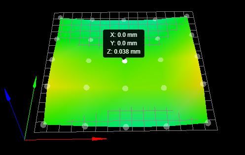
when I was ignoring the x,y probe offset (applied from default on the mesh, but not on the single first G30 probe) the point of the first probing fell between the 0,0 point and the 0,70 point on mesh that have a strong deviation with different sign too: +0.042 and -0.046.
(wtf of luck)
...and the 4 corners at about 0.002mm!!!!(so in the real far away from the real 0,0 point about -0.003mm)
(wtf of luck)
So you can understand, I saw "something" same a mesh "grounded" on the 4 corners!
When I had put the first g30 at the front left corner, similar at the first point probe from the mesh (always ignoring the shift) I saw a mesh shifted down, but also in this time not with the first point at zero as expected!
...than the repeatability error of the probing does the rest.
So such a mess in my brain.
Posts made by sirkris
-
RE: Bed mesh zero reference point?posted in Tuning and tweaking
-
RE: Bed mesh zero reference point?posted in Tuning and tweaking
@Veti Hi, good point!...Done several times and I can say SD on 10 probes is about 0.006mm.
-
RE: Bed mesh zero reference point?posted in Tuning and tweaking
@Phaedrux Yes, my configuration is a little bit complicated, I have several macro that call other macro, I can post all the duet dump.
Anyway: my printer uses two heights probes, one is a mechanical switch and the second one is a inductive probe. The inductive probe is used for all measure on the plate, for example bed leveling, bed mesh, an height measure at a precise point on the plate. The mechanical switch is used only for find the real last height and to set the z offset. It is usefull because hard switch is more stable at temperature variations than a inductive (or bltouch) probe.
I have to post all the macro, because i can't upload a single rar package...my real configuration use several folders...I am not so masochist zhop_up.g zhop_down.g use_mslow.g use_mfast.g use_islow.g use_ifast.g probe_zm_wipe.g probe_zm.g probe_zlevel.g probe_zi.g probe_y.g probe_x.g park_xy.g mswitch_xy.g iswitch_safexy.g homezm_wipe.g homezm.g homezi.g homez.g homey.g homex.g homeall.g heightmap.csv config-override.g config.g coarse_level.g center_xyz.g brush.g bed_mesh_scan.g bed.g
 -
RE: Bed mesh zero reference point?posted in Tuning and tweaking
@Gerrard oh yes...I think so, but it is for understand better the behavior! That you say could be a good explication: "average" of the all z heights.
Yes, I want to take a look at csv. -
Bed mesh zero reference point?posted in Tuning and tweaking

-Printer: voron 2.1 with 4 indipendent z motors
-NPN inductive probe for z offsetHi guys, I don't understand the bed mesh compensation behavior:
- I make first a multi-pass level gantry,cleaning all hightmaps before
(good leveling result with a error around 0.003mm) - Than I make a bed mesh scan: It is preceded from a single z probe centered at x=0 and y=0 to set the z offset relative at the center (for real z offset for inductive probe is set to 0,because I use the mechanical switch for final z offset adjustments)
All z probes....the first single and the bed mesh scan are performed with the same speed, the same current for stepper...etc...etc
Ok so...why I have a resulting map that has a deviation on the center point other than zero?
I would expect that the center point was for me the "reference" point, and therefore all the map was shifted down to have a zero at the center.
- I make first a multi-pass level gantry,cleaning all hightmaps before
-
RE: 3Dtouch doesn't respond properly on M280 S160 commandposted in General Discussion
@dc42 said in 3Dtouch doesn't respond properly on M280 S160 command:
@sirkris said in 3Dtouch doesn't respond properly on M280 S160 command:
Can I find out the frequency which is operating actually on the pwm?
Some multimeters have a Hz setting.
Ok, I have got a multimeters with Hz probing.
I have executed a probe test on fan P0 and it changes the frequency.
I have tested it with the fan connected (because if disconnected it probes nothing), probe between ground and pwm channel.
If I send M106 P0 S0.5 Fxx I can probe xx frequency.
By the way I cannot probe the channel of the 3dtouch (H7 on duex5).
It seems always 50Hz.
Which are the right command that I have to send?
I have tried to use:
M307 H7 A-1 C-1 D-1 into override config
and without it:
;M307 H7 A-1 C-1 D-1
sending after several commands as
M106 P7 S0.5 Fxx
It is right or I'm doing something wrong to test it?
Best regards -
RE: 3Dtouch doesn't respond properly on M280 S160 commandposted in General Discussion
@Phaedrux said in 3Dtouch doesn't respond properly on M280 S160 command:
Is it possible to get a real bltouch to test with?
No alas.
How can I check my duet?
Can I find out the frequency which is operating actually on the pwm?
I want exclude that possibility. -
RE: 3Dtouch doesn't respond properly on M280 S160 commandposted in General Discussion
@Phaedrux Yes, of course I added I1 into m280 commands to invert polarity
-
RE: 3Dtouch doesn't respond properly on M280 S160 commandposted in General Discussion
@Phaedrux No, I had wired the 3 probes directly on the duex5 and also on the duet2wifi to test its. No additional wiring that can give problems.
How can check eventuals damages? I had test several pwm channels and they work the same. -
RE: 3Dtouch doesn't respond properly on M280 S160 commandposted in General Discussion
I have tested it with an external 5v supply , but it doesn't work anyway.I has Erased the firmware at all and installed the new one from zero but I had no luck. I have added the resistor of 240ohm on parallel on signal, no change.What can I check other? Could be changed the frequency of the pwm? How can I check it? What is the frequency of the pwm on duet2?
-
RE: 3Dtouch doesn't respond properly on M280 S160 commandposted in General Discussion
Hi,
Now I can't make work it properly at all. Bouncing during the probing, falling of the pin, false reading etc etc.
Ok I have all 3 my sensor clones, but I can't believe its are all broken or damaged.
Could I have damaged the duex5/duet2wifi connecting a 3dtouch without the "logic trace 5v" cutted?
How can I check my board? for example the 5V output on h7 pwm that I use is 4,9v, Can be poor as voltage? -
RE: 3Dtouch doesn't respond properly on M280 S160 commandposted in General Discussion
@Phaedrux
Yes, it is.
Only sometimes into multi probing the pin bounces.
The weird thing is that it worked fine in the past.
Can be something about the duty cycle setted on the pwm channel?
How can I check it out? -
3Dtouch doesn't respond properly on M280 S160 commandposted in General Discussion
Hi guys,
I have the 3Dtouch (BLTouch clone) connected on the duex5 on PWM7.
I use it from a long time and it worked always fine.
Now after a long hardware upgrade of my printer (with a long stop of connecting the duet2wifi) I have a problem about it.
The sensor responds properly at the commands m280 p7 s10...s90...s120 but not at s160.
When i send m280 p7 s160 it work alarm release but not pull up the pin (as before!).
Sometimes when it performs multiple probes the pin goes down and up " bouncing " also.
The wiring seems right, the voltages are right too. I used 3 different sensor, but the result is the same. I upgraded to firmware 2.05 but nothing.

My setting include several macros but I can confirm that I have these:this in deployprobe.g
m280 p7 s10this in retractprobe.g
m280 p7 s90this in config.g
M307 H7 A-1 C-1 D-1
M558 P9 H5 F120 T4000 X0 Y0 Z1 A1 R0.1 B1
G31 P25 X0 Y27 Z1.5this in override:
;M307 H7 A340.0 C140.0 D5.5 S1.00 V0.0 B0Command modifier " I1" used nowhere because i connected to duex5
What went wrong in your opinion?
Best Regards