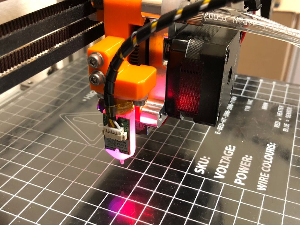
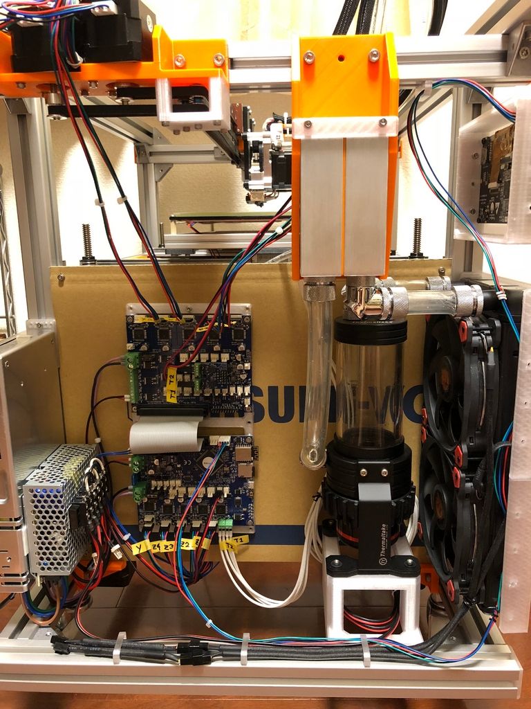
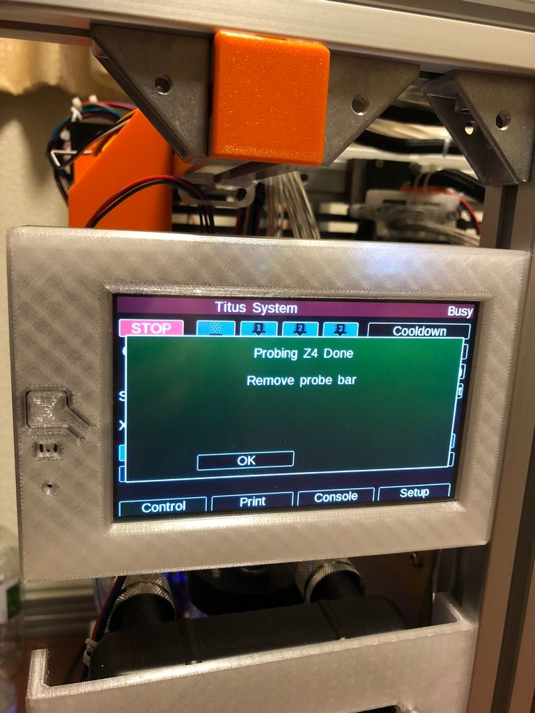
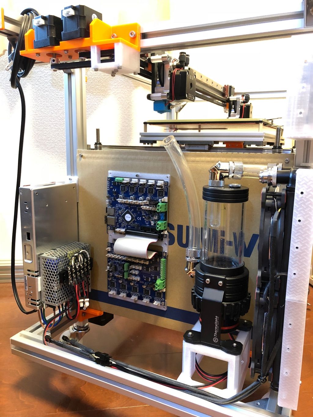
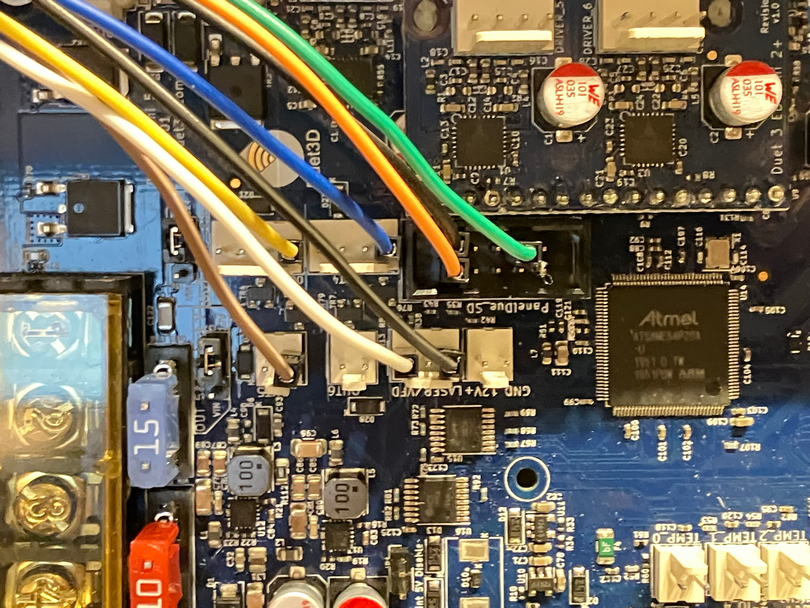
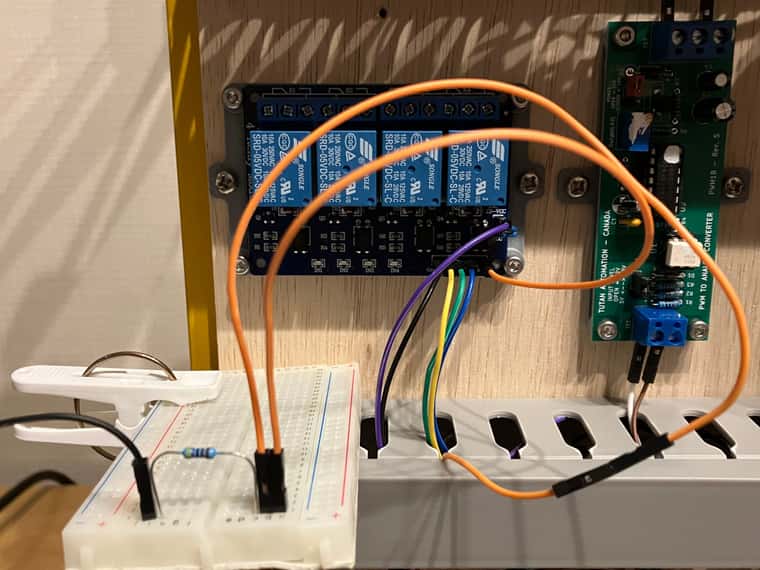
I'm bench-testing my laser rig using Duet3 Mini5+.
I've...
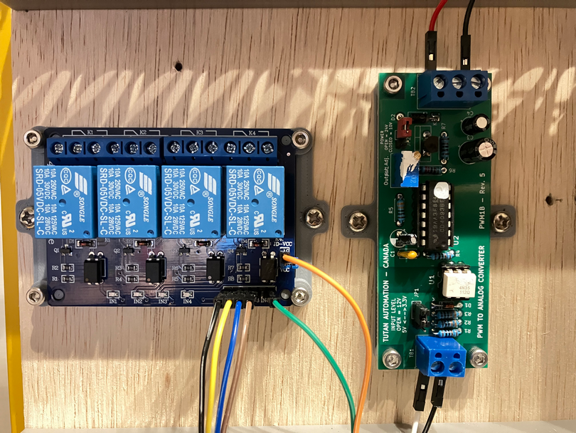
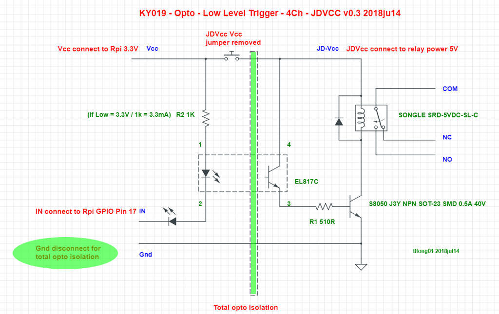
[out6_buffer] === PWM-to-Analog converter for 0~10V laser power single
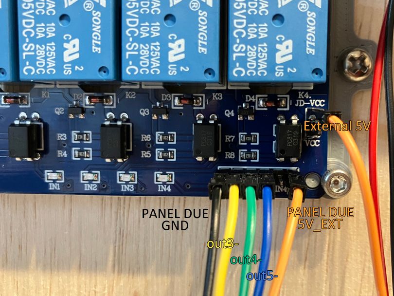
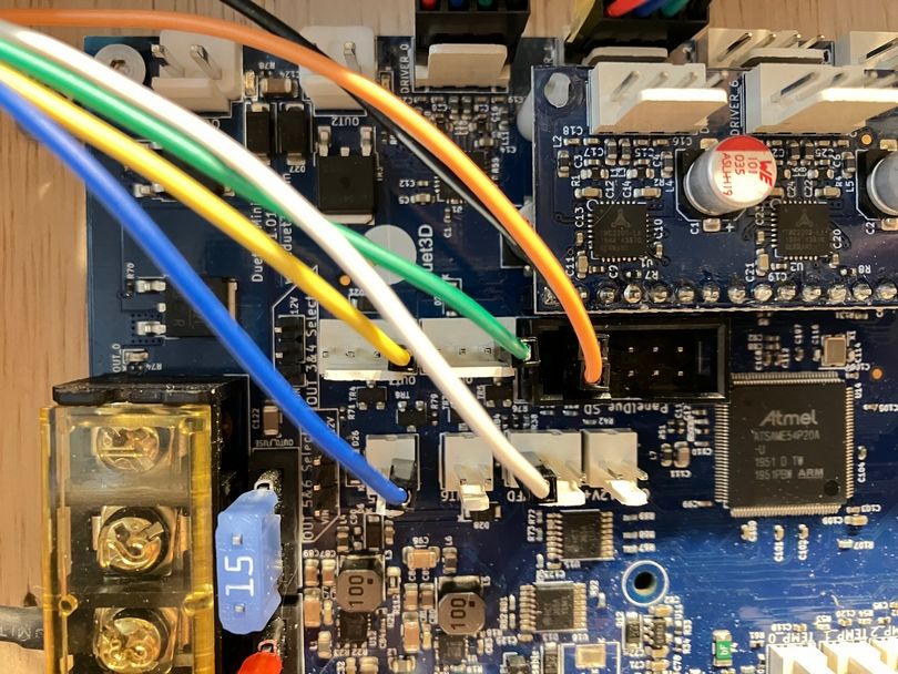
[PANEL DUE GND] === Relay board [GND]
[PANEL DUE 5V_EXT] === Relay board [VCC]
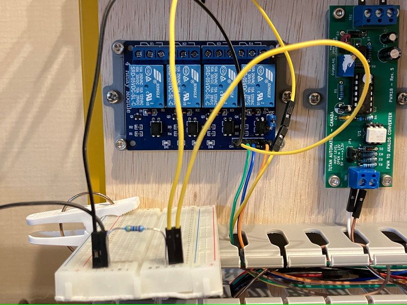
[out3-] === Relay board [IN1]
[out4-] === Relay board [IN2]
[out5-] === Relay board [IN3]
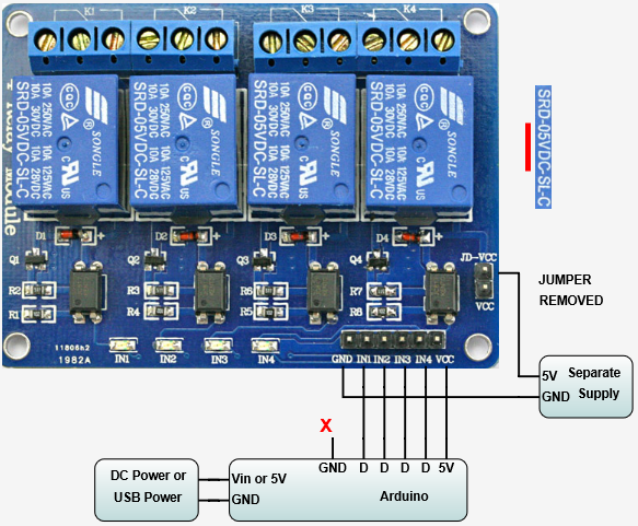
[External 5V] === Relay board [JD-VCC], to power the coil
And in config.g I've...
; Laser mode
M452 C"out6" R255 F200 ; Enable Laser mode, on out6, with max intensity being 255, and a PWM frequency of 200

; FAN-as-IO setup
M950 P0 C"out3" ; Red Laser
M950 P1 C"out4" ; Laser Enable
M950 P2 C"out5" ; placeholder
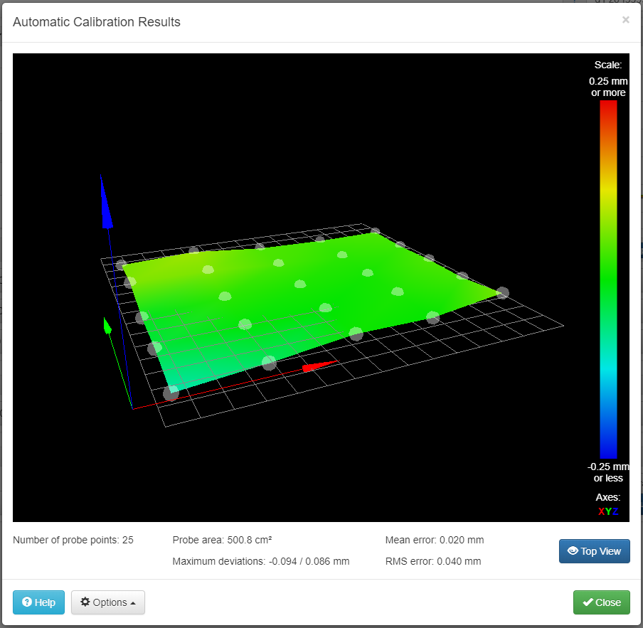
The bench-testing (not wiring to actual laser) seems ok. M42 P0 S1 enable IN1 relay, and M42 P0 S0 disable IN1 relay. P1/P2 also doing the same thing, which is good.
However, at power lost (ex: unplug Duet3), between [out3-] and [PANEL DUE 5V_EXT] will jump from 0V to ~2.7V and slowly bleeding away. While it's not enough to trigger relay, it's there. Same case for [out4-], [out5-].
Is there way to ensure that, at power lost, it stay at 0V ? As I plan to switch to MOSFET later.
(edit: better writing to avoid confusion)
")