Duet3D Logo

    Duet3D

    • Register
    • Login
    • Search
    • Categories
    • Tags
    • Documentation
    • Order
    1. Home
    2. Turricann
    • Profile
    • Following 1
    • Followers 0
    • Topics 8
    • Posts 41
    • Best 3
    • Controversial 0
    • Groups 0

    Turricann

    @Turricann

    3
    Reputation
    7
    Profile views
    41
    Posts
    0
    Followers
    1
    Following
    Joined Last Online

    Turricann Unfollow Follow

    Best posts made by Turricann

    • RE: Triple Z Axis G32 Bed Traming

      @Phaedrux Yes i realized what i had done late as i posted it and removed the H2 on the G1 move you will have to bear with me this is my first attempt @ setting up a 3D printer.

      @jay_s_uk
      Yes everything is in the correct order triple checked this including M671 and probe points.

      @fcwilt you are correct the lead screw points are outside the bed area however the probe points are the position where the bed mount attaches to the bed unless you know of a way to put an offset in for the actual positions ?

      @gloomyandy your description fits my bed setup.

      @CaLviNx just reading through your config should the M671 command come after M584 not before ?
      Referance https://duet3d.dozuki.com/Wiki/Bed_levelling_using_multiple_independent_Z_motors.

      ; bed.g
      ; called to perform automatic bed compensation via G32
      ;

      M561 ; clear any bed transform

      G28 ; home all

      G30 P0 X170 Y30 Z-99999 ; probe near a leadscrew middle right
      G30 P2 X-180 Y-170 Z-99999 ; probe near a leadscrew Front left
      G30 P1 X-190 Y190 Z-99999 S3 ; probe near a leadscrew rear left and calibrate 3 motors

      G1 X0 Y0 F8000
      G30 Z

      ; homez.g
      ; called to home the Z axis
      ;
      G91 ; relative positioning
      G1 H2 Z5 F6000 ; lift Z relative to current position
      G90 ; absolute positioning
      G1 X0 Y0 F6000 ; go to first probe point
      G30 ; use probe to find Z 0
      G91 ; relative positioning
      G1 Z10 F6000 ; lift Z relative to current position
      G90 ; absolute positioning

      posted in General Discussion
      Turricann
      Turricann
    • RE: Heater Will not turn off once started.

      Thanks that is what i needed to sort that issue, I upgraded to try and resolve the original issue about the heater recommended by @T3P3Tony ,

      I will redo config.g now and see what happens with the heaters.. thanks for your support.

      posted in Duet Hardware and wiring
      Turricann
      Turricann
    • RE: Heater Will not turn off once started.

      @droftarts Well after some head scratching and working through my wiring you were dead right i had a short between the two ground plane's on a custom pcb which i was using as breakout board, the issue was when i was metering the hotend i removed the screws to get to the back of the PCB when i done this there is no short, but because i inadvertently connected the two ground planes to via's where the screws went threw the PCB and those screw's went into to a metal plate it caused a short.

      Picked up a tool board from ooznest to replace my PCB.

      Thanks For you support on this.

      posted in Duet Hardware and wiring
      Turricann
      Turricann

    Latest posts made by Turricann

    • RE: Mesh bed leveling

      @phaedrux

      config.g

      ; Configuration file for Duet 3 (firmware version 3.2RC3)
      ; executed by the firmware on start-up
      ;
      ; generated by RepRapFirmware Configuration Tool v3.1.10 on Mon Dec 07 2020 21:49:17 GMT+0000 (Greenwich Mean Time)

      ; General preferences
      G21 ; Work in millimetres
      G90 ; send absolute coordinates...
      M83 ; ...but relative extruder moves
      M550 P"Duet 3" ; set printer name
      M669 K1 ; select CoreXY mode
      G4 S1 ;wait for expansion boards to start
      ;
      ; Drives (20.XX) denotes the Can-Bus address that the toolboard LC1 is operating on
      ;
      M671 X-4.5:190:478.5 Y-3.52:435:-3.52 P0.2 S5 ; Define positions of Z leadscrews or bed levelling screws Ratrig Stock

      M569 P0.3 S1 ; Duet 3 physical drive 0.0 goes backwards (X)
      M569 P0.4 S1 ; Duet 3 physical drive 0.1 goes backwards (Y)
      M569 P0.0 S0 ; Duet 3 physical drive 0.0 goes Forwards (Front Left Motor)
      M569 P0.1 S0 ; Duet 3 physical drive 0.1 goes Forwards (Middle Back Motor)
      M569 P0.2 S0 ; Duet 3 physical drive 0.2 goes Forwards (Front Right Motor)
      M569 P20.0 S0

      M584 X0.4 Y0.3 Z0.0:0.1:0.2 E20.0 ; 3 * Z motors connected, E20.0 = tool board , Need to keep Z in this order to match lead screw postions.

      M350 X16 Y16 Z16 E16 I1 ; configure microstepping with interpolation
      M92 X160.00 Y160.00 Z1600.00 E409 ; set steps per mm for Hamera
      M566 X400.00 Y400.00 Z6.00 E120.00 P1 ; set maximum instantaneous speed changes (mm/min) ratrig stock
      M203 X10800.00 Y10800.00 Z1000.00 E3600.00 ; set maximum speeds (mm/min) ratrig stock
      M201 X5000.00 Y5000.00 Z100.00 E3600.00 ; set accelerations (mm/s^2) ratrig stock
      M906 X1400 Y1400 Z1400 E1000 I30 ; set motor currents (mA) and motor idle factor in per cent
      ;M593 F34.2 <---- look into. ; cancel ringing at 34.2Hz
      M84 S30 ; Set idle timeout

      ; Axis Limits
      M208 X0 Y0 Z0 S1 ; set axis minima
      M208 X400 Y380 Z400 S0 ; set axis maxima

      ; Endstops
      M574 X1 S3 ; configure sensorless endstop for high end on X
      M574 Y1 S3 ; configure sensorless endstop for high end on Y
      M574 Z1 S2 ; Set endstops controlled by probe

      ; Z-Probe
      M950 S0 C"20.io0.out" ; create servo pin 0 for BLTouch
      M558 P9 C"^20.io0.in" H5 F100 R0.2 T6000 A5 B1 ; set Z probe type to bltouch and the dive height + speeds
      G31 P25 X32.5 Y-42 Z5.492 ; set Z probe trigger value, offset and trigger height
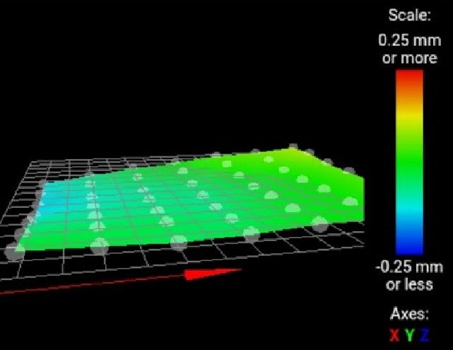
      M557 X35:400 Y30:320 P7 ; define 5x5 mesh grid

      ; Bed Heaters
      M308 S0 P"temp0" Y"thermistor" T100000 B3950K ; configure sensor 0 as thermistor on pin temp0
      M950 H0 C"out0" T0 ; create bed heater output on out0 and map it to sensor 0
      M307 H0 B1 S1.00 ; enable bang-bang mode for the bed heater and set PWM limit
      M140 H0 ; map heated bed to heater 0
      M143 H0 S120 ; set temperature limit for heater 0 to 120C

      ; Hotend Heaters
      M308 S1 P"20.temp0" Y"thermistor" T100000 B4725 C7.06e-8 ; Toolboard configure sensor 0 as a E3D thermistor on pin temp0
      M950 H1 C"20.out0" T1 ; Toolboard create nozzle heater output on out1 and map it to sensor 1
      M307 H1 B0 S1.00 ; disable bang-bang mode for heater and set PWM limit
      M143 H1 S301 ; set temperature limit for heater 1 to 301C

      ; Fans
      M950 F0 C"20.out1" ;Toolboard create fan 0 (Hotend cooling) on pin out1 and set its frequency
      M106 P0 S0 H1 T10 Q500 L255 ; set fan 0 value. Thermostatic control is turned off

      M950 F1 C"20.out2" Q500 L255 ; Toolboard (Partcooling) Fan1 on pin out2 and set its frequency
      M106 P1 S1 H1 T45 ; set fan 1 value. Thermostatic control is turned on

      ; Fan for cooling duet
      M308 S2 Y"drivers" A"DRIVERS" ; configure sensor 2 as temperature warning and overheat flags on the TMC2660 on Duet
      M308 S3 Y"mcu-temp" A"MCU" ; configure sensor 3 as thermistor on pin e1temp for left stepper
      M950 F2 C"out7" Q100 ; create fan 2 on pin fan2 and set its frequency
      M106 P2 H2:3 L0.15 X1 B0.3 T40:70 ; set fan 2 value

      ; Tools
      M563 P0 D0 H1 F0 S"HOTEND" ; define tool 0
      G10 P0 X0 Y0 Z0 ; set tool 0 axis offsets from bed center.
      G10 P0 R0 S0 ; set initial tool 0 active and standby temperatures to 0C

      ;Custom settings are not defined

      ; Linear Advance
      M572 D0 S0.03
      ; Retract
      M207 P0 S1.8 F2400 Z0.3 ; default Hemera retract settings

      ; Miscellaneous
      M575 P1 S1 B57600 ; enable support for PanelDue
      M501 ; load saved parameters from non-volatile memory
      M911 S10 R11 P"M913 X0 Y0 G91 M83 G1 Z3 E-5 F1000" ; set voltage thresholds and actions to run on power loss
      T0 ; select first tool

      bed.g

      ; this script compensates for what the Z offset is
      ; so if G31 P500 X-30 Y-15 Z1.7 then first probe will be at
      ; X30 Y20 (when G30 P0 X0 Y5)

      M561 ; clear any bed transform
      G28

      G30 P0 X35 Y5 Z-99999 ; probe near front left leadscrew
      G30 P1 X200 Y335 Z-99999 ; probe near Rear leadscrew
      G30 P2 X400 Y5 Z-99999 S3 ; probe near Right leadscrew and calibrate 3 motors

      G30 P0 X35 Y5 Z-99999 ; probe near ;front left leadscrew
      G30 P1 X200 Y335 Z-99999 ; probe near ;Rear leadscrew
      G30 P2 X400 Y5 Z-99999 S3 ; probe near ;Right leadscrew and calibrate 3 motors

      G29 ; probe the bed and enable compensation

      G1 X200 Y200

      posted in Using Duet Controllers
      Turricann
      Turricann
    • RE: Mesh bed leveling

      When i run 3 point bed traming its as if front left is low by .1mm and rear right is high by around .1mm so the theroy is if i can add a manual offset to on point my bed would be level.

      Motors are positioned Front left and right and one rear center.

      bed.jpg

      posted in Using Duet Controllers
      Turricann
      Turricann
    • RE: Heater Will not turn off once started.

      @droftarts there's always a possibility but they are two independent runs straight back to the board, I have checked the cable for short but not between theater and fan.

      posted in Duet Hardware and wiring
      Turricann
      Turricann
    • Mesh bed leveling

      Is it possible on a duet 3 6hc to atrim each axis manually?

      Reason I ask is when I run 3 point bed leveling it seems to tram the bed but it leave a slight off set on one axis.

      posted in Using Duet Controllers
      Turricann
      Turricann
    • RE: Tool board Failure during Print

      @dc42 Thanks I have contacted ooznest who was the supplier.

      posted in Duet Hardware and wiring
      Turricann
      Turricann
    • RE: Tool board Failure during Print

      5 weeks old, yep printed quite a few things used about 1/2 a roll of PETG and was just finishing a E3D Hemera mount when it failed.

      posted in Duet Hardware and wiring
      Turricann
      Turricann
    • RE: Tool board Failure during Print

      No Connected everything except motor to duet and it works fine. checked motor wiring with meter and all seems ok . Blue led and red led lit solid on tool board but no comms and does nothing if you try to reset the tool board oh and hotend cooling fan come on as expected.

      The board had been working perfectly been used for the last two weeks printing upgrades for my printer.

      Current Firmware RRF3.2

      System setup Pi3 to Duet 3 6hc connected to tool board,

      Config.g

      ; General preferences
      G21 ; Work in millimetres
      G90 ; send absolute coordinates...
      M83 ; ...but relative extruder moves
      M550 P"Duet 3" ; set printer name

      M669 K1 ; select CoreXY mode

      M569 P0.0 S0 ; Duet 3 physical drive 0.0 goes backwards (X)
      M569 P0.1 S1 ; Duet 3 physical drive 0.1 goes backwards (Y)
      ;M584 P0.2 S0 ; Empty Header for Extruder Motor.
      M569 P0.3 S0 ; Duet 3 physical drive 0.3 goes backwards (Z1 Right Middle Motor)
      M569 P0.4 S0 ; Duet 3 physical drive 0.4 goes backwards (Z2 Front left Motor)
      M569 P0.5 S0 ; Duet 3 physical drive 0.5 goes backwards (Z3 Back Left Motor)
      M569 P20.0 S0
      M584 X0.0 Y0.1 Z0.3:0.4:0.5 ; 3 * Z motors connected to 0.3 (Right Middle), 0.4 (Front left), 0.5 (Back Left Motor) Need to keep in this order to match lead screw postions.
      M584 E20.0 ; set drive mapping -- tool board
      M350 X16 Y16 Z16 E16 I1 ; configure microstepping with interpolation
      M92 X160.00 Y160.00 Z1600.00 E839.86 ; set steps per mm M92 Z400 for 1.8º degree steppers and M92 X160 Y160 for 0.9º (calculated extruder 839.86)

      M671 X205:-205:-205 Y0:-205:205 S20 ; Bed Pivot points Where kinnermatic mounts are located the Actual leadscrews Positions @ Right middle (X245 Y30),Front left (X-245 Y-173), left Rear (X-245 Y-225) (Sxx = tollerance ie 20mm)

      M566 X600.00 Y600.00 Z360.00 E600.00 P1 ; set maximum instantaneous speed changes (mm/min)
      M203 X6000.00 Y6000.00 Z600.00 E1200.00 ; set maximum speeds (mm/min)
      M201 X3000.00 Y3000.00 Z120.00 E120.00 ; set accelerations (mm/s^2)
      M906 X900 Y900 Z900 E800 I30 ; set motor currents (mA) and motor idle factor in per cent
      ;M593 F34.2 <---- look into. ; cancel ringing at 34.2Hz
      M84 S30 ; Set idle timeout

      ; Axis Limits
      M208 X-195 Y-195 Z0 S1 ; set axis minima
      M208 X200 Y200 Z450 S0 ; set axis maxima

      ; Endstops
      M574 X1 S3 ; configure sensorless endstop for high end on X
      M574 Y1 S3 ; configure sensorless endstop for high end on Y

      ; Z-Probe
      M574 Z1 S2 ; Set endstops controlled by probe
      M558 P8 C"^20.io0.in" I1 H10 F500 T6000 ; Toolboard P8 Z probe mode for ToolBoard, Prusa PindaV2 sensor config.(F= Bed speed to probe.) (H= distance bed moves during probing) ( S= tollerance) (p= probe type)
      M308 S2 P"20.temp1" A"Pinda V2" Y"thermistor" A20 T100000 B3950 ; Toolboard, Prusa PindaV2 temperature config.
      G31 P500 X-30 Y15 Z0.235 ; set Z probe trigger value, offset and trigger height
      M557 X-180:180 Y-170:170 S42 ; define mesh grid

      ; Bed Heaters
      M308 S0 P"temp0" Y"thermistor" T100000 B3950K ; configure sensor 0 as thermistor on pin temp0
      M950 H0 C"out0" T0 ; create bed heater output on out0 and map it to sensor 0
      M307 H0 B1 S1.00 ; enable bang-bang mode for the bed heater and set PWM limit
      M140 H0 ; map heated bed to heater 0
      M143 H0 S120 ; set temperature limit for heater 0 to 120C

      ; Hotend Heaters
      M308 S1 P"20.temp0" Y"PT1000" ; Toolboard configure sensor 0 as a PY1000 thermistor on pin temp0
      M950 H1 C"20.out0" T1 ; Toolboard create nozzle heater output on out1 and map it to sensor 1
      M307 H1 B0 S1.00 ; disable bang-bang mode for heater and set PWM limit
      M143 H1 S301 ; set temperature limit for heater 1 to 301C

      ; Fans
      M950 F0 C"20.out1" ;Toolboard create fan 0 on pin out1 and set its frequency
      M106 P0 S0 H-1 Q500 ; set fan 0 value. Thermostatic control is turned off
      M950 F1 C"20.out2" Q500 ; Toolboard Partcooling Fan1 on pin out2 and set its frequency
      M106 P1 S1 H1 T45 ; set fan 1 value. Thermostatic control is turned on
      M950 F2 C"out7" Q500 ; Toolboard Partcooling Fan1 on pin out2 and set its frequency
      M106 P1 S1 H1 T25 ; set fan 1 value. Thermostatic control is turned on

      ; Tools
      M563 P0 S"HOTEND" D0 H1 F0 ; define tool 0
      G10 P0 X-9 Y-13 Z0 ; set tool 0 axis offsets from bed center.
      G10 P0 R0 S0 ; set initial tool 0 active and standby temperatures to 0C

      ;Custom settings are not defined

      ; Retract
      ;M207 P0 S1.8 F2400 Z0.3

      ; Miscellaneous
      M575 P1 S1 B57600 ; enable support for PanelDue
      M501 ; load saved parameters from non-volatile memory
      M911 S10 R11 P"M913 X0 Y0 G91 M83 G1 Z3 E-5 F1000" ; set voltage thresholds and actions to run on power loss
      T0 ; select first tool

      posted in Duet Hardware and wiring
      Turricann
      Turricann
    • RE: Tool board Failure during Print

      @Turricann said in Tool board Failure during Print:

      During my Last Print approx 2h in the print failed after a reset i have lost all comms to the toolboard,

      Capture.JPG

      I have disconnected everything except power and comms,

      looking for ideas to whats gone wrong.

      Well found the Issue the driver on the tool board has a hole in it.

      Screenshot_20210122-203737_Gallery.jpg

      posted in Duet Hardware and wiring
      Turricann
      Turricann
    • Tool board Failure during Print

      During my Last Print approx 2h in the print failed after a reset i have lost all comms to the toolboard,

      Capture.JPG

      I have disconnected everything except power and comms,

      looking for ideas to whats gone wrong.

      posted in Duet Hardware and wiring
      Turricann
      Turricann
    • RE: Triple Z Axis G32 Bed Traming

      @fcwilt

      I have changed the M671 leadscrew Positions from where the leadscrews are to the pivot points under the bed as in @CaLviNx config.g example.

      The bed leveling now seems more consistant,
      1/2/2021, 9:51:43 PM G32
      Leadscrew adjustments made: 0.291 0.320 0.311, points used 3, (mean, deviation) before (0.307, 0.010) after (-0.000, 0.000)
      1/2/2021, 9:50:43 PM G32
      Leadscrew adjustments made: 0.307 0.299 0.307, points used 3, (mean, deviation) before (0.305, 0.004) after (-0.000, 0.000)
      1/2/2021, 9:49:43 PM G32
      Leadscrew adjustments made: 0.308 0.294 0.297, points used 3, (mean, deviation) before (0.300, 0.005) after (-0.000, 0.000)

      posted in General Discussion
      Turricann
      Turricann