Indirect (bearing) laser filament monitor concept
-
Wasnt sure if I should start a new thread, hopefully its ok just to add here, I printed the concept above from brunofporto with the latest changes by adrian52.. but I don't have the right bearings on hand to properly test. Was going to take a while for bearings to get delivered..
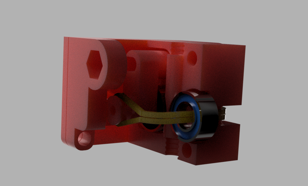
So I decided to have a go at trying to come up with my own design. The goal was to use some decent quality bearings I had on hand - 5x10x4 (mr105) and because I figured it would be something I would be printing different version of, something that was quick & easy to assemble.
So here's my attempt:

I have tried various sensor to bearing surface distances so far.. and I'm finding that around 9mm seems to be the most consistent.
Here is a output from a recent print:

So far it seems to work really well - quite similar to adrian52's results. If you normalise the raw average figure of 299 to be 1 (or 100%) then the lowest reading is 0.956 (4.5% below the average) and the highest reading is 1.023 (2.3% above the average.
I have short tube of around 25mm between the sensor and my extruder input.. so I have set the check to be every 5mm instead of the 3mm in the example which still allows plenty of time to pause the printer if there is an issue, but the slightly longer check also seems to help a bit with consistency.
I have put my stl's and .scad file on thingiverse for anyone to use/mod/try
-
@crash69 Loved your solution for the barings holder!!!!! These bearings are easier to find around here and also cheaper. I'll buy them ASAP and test your design.
 Thanks!
 -
I have been continuing to play with the monitor, and have also made a version for 10mm bearings - I have put it on thingiverse, 3717158. I have made the jaws part spring loaded, so that you can adjust the tension gripping the filament.
When printing slowly, the maximum and minimum values are very accurate (within 2-5%, as above). With faster extrusion, the range tends to get bigger. Using longer measuring intervals seems to give less variation - I am currently using 10mm. Using the A1 switch seem to give a very accurate measure of the total filament used - sometimes giving uncanny agreement with the value reported by DWC (my last print the monitor reported 1640mm, DWC 1639mm, and the slicer said 1643mm). When I use the A0 switch, the monitor reports 85-90% of the filament usage reported by DWC. The total usage data seems to remain extremely accurate when printing faster, where the maximum and minimum values become very wide. Could the max/min variation be due to hitting limits of processing the data? -
It could be that the synchronisation in firmware between the filament sensor reading and the extrusion commanded isn't always working properly.
Duet WiFi hardware designer and firmware engineer
Please do not ask me for Duet support via PM or email, use the forum
http://www.escher3d.com, https://miscsolutions.wordpress.com -
@dc42 have done some more tests using a 20x20x4mm cube with 100%fill, printed at 60mm /sec, then varying the layer height or width to achieve specific filament movement rates. I print the first layer at 10mm/sec, so checking after 100 mm gives a 'slow' baseline for each test, and the total is a little over 700mm. Under these conditions I have no hiccups or missed steps.
For me, the monitor works well with filament movements up to 1.3mm/sec (max/min within 10% of the average) , but for 1.5mm/sec and 2mm/sec, the max/min range becomes very wide, often going negative on the min side. I get similar results with and without a 5mm spacer, although the actual numbers are higher with the spacer as previously observed.
The total extrusion reported by the monitor is very close (usually within 1%) to that shown by dwc or the slicer, even when the extrusion rate is above 1.5mm /sec.
I have also started to note the error rates for the monitor reported by M122. For tests below 1.3mm/sec, frame errors are 2000-4000, and pol errors high(20000-30000). Above 1.3mm/sec, frame errors are 20000 - 30000, but pol errors are below 10000. I have also noticed that the error count is not zeroed when you start a new print - I have been doing a reset after each test to zero things up. -
@adrian52, what is that you are trying to achieve? If it's the detection of filament grinding, do you need exact measurements or just no movement in a certain time period?
-
@adrian52 What is curious is that I had similar results (high precision with total measured length compared to predicted by slicer) with direct filament readings!!! It was precise enough that I could even calibrate extrusion steps/mm with it. Even with filaments that I had horrible max and min results.
-
@adrian52 said in Indirect (bearing) laser filament monitor concept:
I have also started to note the error rates for the monitor reported by M122. For tests below 1.3mm/sec, frame errors are 2000-4000, and pol errors high(20000-30000). Above 1.3mm/sec, frame errors are 20000 - 30000, but pol errors are below 10000.
Hmm, that sounds odd. Which firmware version are you running? Run M115 to make sure. Also, which revision Duet do you have? We changed the values of the filtering capacitors on later ones to help the filament monitor signals get through more reliably.
Duet WiFi hardware designer and firmware engineer
Please do not ask me for Duet support via PM or email, use the forum
http://www.escher3d.com, https://miscsolutions.wordpress.com -
@dc42 running 2.03+1. I have a 1.01 duet wifi. Is there a way I can improve the situation?
-
You could try connecting the filament monitor to one of the endstop inputs on CONN_LCD, which have no filter capacitors. That would be easier than removing the filter capacitor from a regular endstop input on the Duet. But if the problem is interference from a stepper motor cable, it may make matters worse.
Keep the cable to the filament monitor away from the extruder motor cable; or if they must run together, try using shielded cable for the filament monitor.
Duet WiFi hardware designer and firmware engineer
Please do not ask me for Duet support via PM or email, use the forum
http://www.escher3d.com, https://miscsolutions.wordpress.com -
@dc42 Excellent advice. I have connected to stop 10 on conn_lcd using shielded cable (a repurposed USB cable that also has a ferrite ring), and the errors are now zero. I have got up to 3mm/second filament (0.5 width, 0.3 height at 60mm/sec) and the max/min were 107%/95% of the average. Wow.
-
@crash69 Thank you for this; I really like your design (it printed like a charm)! Also, your .scad file is straightforward to tweak. I have changed the following:
- Added a bracket to attach to my Ender 3 with a SeeMeCNC EZR Struder;
- Increased the sensor distance to 19mm (thanks @Adrian52 for the analysis);
- Made the split on the bearing mounts longer, to make it easier to slide the bearings in;
- Adapted the bearing size to some bearing I had lying around (16x8x5).
I did a quick test with a shorter sensor distance; the results were much better than with direct reading, but I still got a wide range. In the next few days, I will print another one with all the changes listed above. If anybody is interested, I can publish the remix.
Thank you all for this very informative thread.
-
@taglia Please do publish!
-
@brunofporto Apologies for the long silence, it took me a while to get to some good results. I have now managed to print for a couple of days with consistent results and no sudden pauses. The sensor also saved a big part that I was printing (no more filament).
The cause of my problems was the filament sliding on the bearing, and this caused negative reads. I have found this product at a local shop, sprayed two layers on my bearings, and the sensor seems now stable, even at high speed. I have also increased the pressure a bit and reprinted the mount with black eSun PLA+, which appears to be stronger than regular PLA.
This is the model that I am currently using. I was too lazy to remodel the attachment to the extruder, which I had already designed in Fusion 360: this is the STL imported by the OpenSCAD file.
These are the bearings.
-
Anybody determine the optimized number for "E" with an indirect bearing setup? I see someone using E5, but I get no data with E5. E4 seems to work.
Duet3D laser filament monitor v1 on input 3, disabled, allow 10% to 75%, check every 4.0mm, version 1, measured min 17% avg 30% max 47% over 246.5mm
Duet3D laser filament monitor v1 on input 3, enabled, allow 10% to 70%, check every 4.0mm, version 1, measured min 14% avg 29% max 54% over 2218.6mm
BTW, what is different about the version 2 sensor? Or is it a firmware difference?
-
@Crash69 said in Indirect (bearing) laser filament monitor concept:
5x10x4 (mr105)
Hi everyone, I just published my interpretation for a Duet3D laser filament monitor enclosure. Use a rubber band and have moving parts.
https://www.thingiverse.com/thing:4147811
-
Thank you very much for your idea. I do little improvement on bearings I put there black heat shrink tube. Between bearings and heat shrink tube I put chemoprene glue and everythink works fine. Surface is black and scanning is stable:
Duet3D laser filament monitor v1 on input 4, enabled, allow 15% to 250%, check every 6.0mm, version 1, measured min 154% avg 166% max 174% over 6397.2mm
This values are stable for all materials which I tested yet.
-
@brunofporto said in Indirect (bearing) laser filament monitor concept:
F623ZZ
Love this design, did you redesign for F623ZZ or will the present config work?
-
An interesting remix is out there as well.
https://www.thingiverse.com/thing:4341389I found most of the parts on amazon but it can get a bit spendy. I would like to see the roller pulley as a micro switch so it could be used as a static filament sensor for startup and filament change macros.
Carbon Fiber Rod 5mm
https://amzn.to/3agj6McU604 Bearing
https://amzn.to/2PE3Wa4MR95ZZ Bearing x 2
https://amzn.to/3fJYTPMEmbedded Bowden Coupling for Metal for E3D heatsink x 1
https://amzn.to/3akDv2NBelt Tensioner Spring
https://amzn.to/3ijLIqDExtruder PUlly 36T
https://amzn.to/31N5rsfM3 Insert Brass Nut
https://amzn.to/3kqOkEO -
@Adrian52 said in Indirect (bearing) laser filament monitor concept:
@dc42 Excellent advice. I have connected to stop 10 on conn_lcd using shielded cable (a repurposed USB cable that also has a ferrite ring), and the errors are now zero. I have got up to 3mm/second filament (0.5 width, 0.3 height at 60mm/sec) and the max/min were 107%/95% of the average. Wow.
@Adrian52 , Are you saying that by using the direct filament (stock so to speak) enclosure you are getting zero errors now that you have a shielded cable running from your sensor to the board? I am debating on attempting your indirect enclosure concept but if you had success by making a wiring modification perhaps that is a better way to fix this.
Also, Any chance you would want to factor in a roller micro switch into your mod so that the sensor can be used as a static filament present sensor as well?