Configuring 12864 LCD on Maestro?
-
@dc42 it work the same not needed
")
-
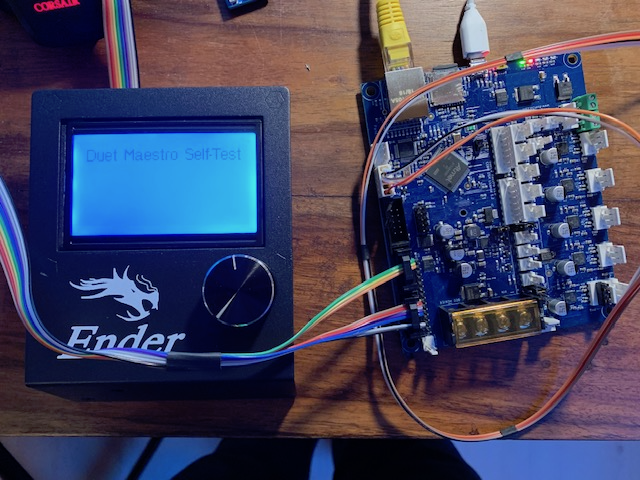
Hi, First post here, I thought that may help you guys out a bit...
If anyone else wants a simple clean way to create a single ribbon cable which does not involve dupont connectors: You can easily crimp yourself a cable, just get yourself some connectors (like this one, no affiliation with sparkfun). You can either reuse the existing cable or, simpler, get some rainbow ribbon cable which allows you to follow this color scheme:

All connectors as seen from the top, i.e. the order in which the pins are on the connectorsCrimp the cable on the LCD side with all wires, if using a rainbow ribbon align the marker (small triangle) with the brown wire so that the colors match up the illustration. Carefully cut the ribbon after two wires, in the center and finally just before the outer two wires. For the EXP1 connector align the first two and last two wires identical to their position on the LCD side. Take the second three wire pair and align it flipped over with the first wires. The top "bridge" of the connector has some indentations which helps with the proper alignment. You should have three remaining wires, these go into the exp2 connector, again flipped over. make sure to skip the first two positions and you should be fine.
Happy crimping!
--Edit--
Configuration when using this wiring to have the wheel inputs properly working:
M918 P1 E-4Voron V2.434 / Duet 3 Mini5+, Duet 3 Expansion Mini 2+, Duet 1LC V1.1 Toolboard
Voron V0.250 / Duet 2 Maestro -
@puterpro said in Configuring 12864 LCD on Maestro?:
@jameswood said in Configuring 12864 LCD on Maestro?:
Just a quick note to thank you all for pointing me in the right direction to get my Creality CR-10S screen working with the Maestro.
And a quick Thank YOU for confirming what I thought I needed to do on my CR-10S
 Complete with picture. Nice!!
EDIT: Ahhh ... Just looked at my 12864 board and I don't have a EXP3 header at all. When did you get your 10S?
Mine was from Nov 17. Did they add an SD Card to it later or something?Hey @puterpro - The good news is that you don't need EXP3 at all!
EXP3 is a combination of pins from EXP1 and EXP2, which is used on some Creality printers as a single-cable connection instead of 1 and 2. It's basically redundant, and not needed when connecting the screen to the Duet Maestro. Just connect EXP1 to EXP1 and EXP2 to EXP2 (after flipping them both on the screen board!!) and you'll be golden. This approach uses the original ribbon cables with no chopping.
My printer is a few months old now, I spose... yours might be newer. I have no SD reader on the screen board.
(Oh and so sorry for the slow reply!)
-
@jameswood Thanks! I have it hooked up and working with the two cables (reversed the plastic to fix polarity), was just curious if EXP3 was setup for SD card use. Just curiosity, no real need...
It works fine but the contrast is terrible. Seems there's a pot to adjust it on most boards but if there's one on this one I sure can't find it!! Don't want to desolder the boards to look, but not visible from the edges.
I'll control it from a touchscreen PC so the 12864 is strictly for redundancy. Thanks for the info!!
-
@pixelpieper Thanks! Nice explanation!!
-
@puterpro My contrast improved significantly once I ran the Maestro board of 24V rather than USB. Seems to be an issue with the supply...
-
@pixelpieper Thanks, that makes some sense as they do tend to be voltage sensitive, as anyone with YOUR screen name should know. LOL!
My old setup was running 13.2v, new is an ATX @ 12.2v.
I'm running without a display currently as I have a PC right next to it, it's on my list to handle but low priority right now. I'll get back to it and if it's too naughty I'll get a cheap one from China ...
24v is on my Wish List but the
WifeFinance Committee is currently recovering from shock from all the upgrades right now.
-
If you have the on-board 5V regulator enabled, then the contrast on the 12864 display can be expected to change when you switch from USB power to VIN power (or provide both - the VIN power will take over). This is because the 5V rail is only about 4.6V when powered from USB alone, but a true 5V when powered from VIN. However, increasing VIN from 12V to 24V shouldn't make any difference to the contrast.
There are two places where the contrast pot may be:
-
Mounted on the back of the LCD PCB (the green one), so the red PCB gets in the way of adjusting it. If you orient the unit so that you are looking into the SD card socket opening with the LCD on the underside, the pot is slightly behind and to the left of the back left corner of the SD card socket. Some of these display/encoder combos have a hole close to one corner of the SD card socket, to provide access to the pot.
-
Mounted near the bottom left corner on the front of the red PCB. Most of the current listings on Amazon and eBay show it in this position.
-
-
I know this is an old topic but in case people are searching and relying on the information I tried to reconcile the different common styles with pictures of the LCD itself and cable, so it is easier to identify which ones you need. See the pictures in this post:
Bottom line, if you don't know it's simple: if the LCD doesn't power on, flip one end of your LCD cables, cutting the keying feature if it's in the way.
-
Whew . So I think I got it. I just want to clarify before i chop an end off my ribbon cable.
Q: I CAN USE THE ORIGINAL 10 PIN RIBBON CABLE TO DO WHATS
NEEDED TO BE FULLY FUNCTIONAL WHEN INSTALLING DUET WIFI
INTO ENDER 3 BY FOLLOWING THE DIAGRAM ON PIXELPIEPERS
2/4/2019 POST ABOVE?
A: YES or NO?Thanks to all of you I'm brand new and just want to finally get to print some stuff.
-
@abstraktlighting said in Configuring 12864 LCD on Maestro?:
DUET WIFI
no the duet wifi is not supported
-
This post is deleted! -
By the way: no need to cut off anything, usually you can carefully lift the black plastic receptacle for the ribbon cable on the LCD and put it back on turned 180°.
-
I don't want to beat a dead horse but is there any way to use the 12864 lcd with a duet wifi? If not what about the tft28? Thx
-
Never mind the first question. Seems like thats still impossible without building hardware. But any thoughts on a tft28?