slant lines
-
@arhi said in slant lines:
The worm sits in the two bearings, one on each end
The worm sits on just 1 bearing, the other on top doesn't hold the worm but it is just leaning on it. That is in my opinion the first design issue with that extruder.
-
holy s*$#t!
So I put a bondtech extruder in direct drive on a mosquito. I had to redo the whole head, but I had to try.
The overall quality is good but.... I still get the slant lines! They are completely different but they are still there. I am going nuts! I don't know what else to try...
-
Have you tried a different driver for the extruder yet?
-
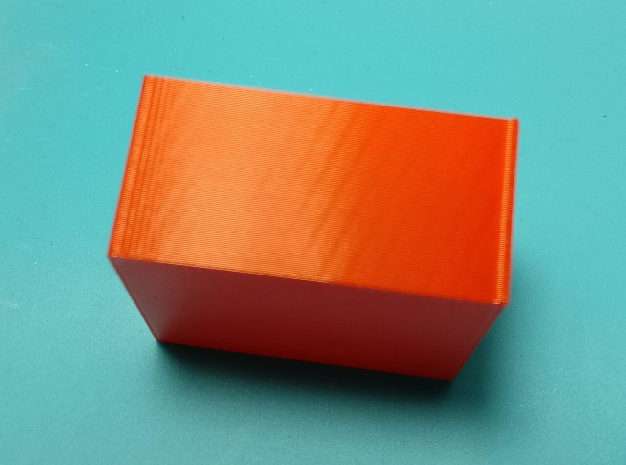
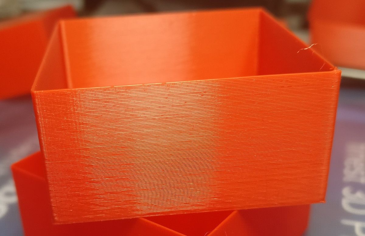
@matt3o, if you print a box with a thin single perimeter wall, do you see the lines on both sides of the wall? If so, are they symmetric or opposite?
(trying to distinguish between X/Y irregularity and extrusion width irregularity.)
-
@Phaedrux said in slant lines:
Have you tried a different driver for the extruder yet?
I tried on a new driver on the duex5, no difference. Do you think it is woth trying on the main duetwifi?
@zapta said in slant lines:
@matt3o, if you print a box with a thin single perimeter wall, do you see the lines on both sides of the wall? If so, are they symmetric or opposite?
(trying to distinguish between X/Y irregularity and extrusion width irregularity.)
The pattern is the same on all sides, from bottom left to top right (this time). Looking at the same side the pattern is the same in the inside and the outside.
-
@matt3o said in slant lines:
Do you think it is woth trying on the main duetwifi?
When you're grasping at straws... why not?
-
@Phaedrux said in slant lines:
When you're grasping at straws... why not?
Yes, that's correct. Possibly having larger pulleys on the secondary belt will allow to reduce tension there without increasing backlash (and having non equal pulleys may allow increasing the steps/mm).
-
@matt3o said in slant lines:
The pattern is the same on all sides, from bottom left to top right (this time). Looking at the same side the pattern is the same in the inside and the outside.
Do you mean that where it bulges on one side of the wall it also bulges on the other side of the wall? If so I would think it's uneven extrusion.
(I presume it's not related to Z issues such as automatic bed mesh compensation which can also affect the extrusion width).
-
I tried 2 drivers on the duex and 1 on the duetwifi. No difference whatsoever. @Phaedrux thanks for the suggestion, I really hoped that would work.
I changed cables. Niet.
I tried a new motor. Nada.
What the f...
@zapta the texture is so faint that I can't really tell what XY direction it is going. I'd probably need a microscope, I'll try to take some macro shots but I don't know if that would be enough.
-
@matt3o said in slant lines:
@arhi said in slant lines:
The worm sits in the two bearings, one on each end
The worm sits on just 1 bearing, the other on top doesn't hold the worm but it is just leaning on it. That is in my opinion the first design issue with that extruder.
You sure? I know the original design I had was holding both bearings strongly... will check the G5
there are bearings on both side ... ah you are right I just checked the worm does not go in to the bearing on top only the flex goes trough the bearing

-
@zapta said in slant lines:
Do you mean that where it bulges on one side of the wall it also bulges on the other side of the wall? If so I would think it's uneven extrusion.
That's what I had (have on this print I dug from the trash). The Z is even, the XY is even the amount of plastic varies sinusoidally.
(I presume it's not related to Z issues such as automatic bed mesh compensation which can also affect the extrusion width).
nope, not Z related I'd say
-
@matt3o said in slant lines:
So I put a bondtech extruder in direct drive on a mosquito. I had to redo the whole head, but I had to try.
are they the same frequency as the one you had with flex3drive. Bondtech also comes with a gear
")
what else to try
I'd up the current on the extruder motor to try out that too
-
@arhi said in slant lines:
You sure? I know the original design I had was holding both bearings strongly
the top bearing doesn't hold the worm gear, it is just leaning on it. so if the shaft end is just slightly bent the top bearing will help very little.
@arhi said in slant lines:
I'd up the current on the extruder motor to try out that too
I'm afraid I tried that already
-
@matt3o yes, I opened it up .. the worm is not going in the top bearing
.. dunno if the top bearing is tight around the flex ... anyhow, I don't have slant lines with flex3drive+e3d, had with flex3drive+mellow. you have it now without flex so there must be something else -
okay, it took me a while but I reprinted all the pieces of my printer with a stronger filament. Changed motors. Changed pulleys and idlers and checked them with a dial gauge. Tried various belt tensions.
The result is always the same and it's very frustrating.
The only things left to try are the leadscrews (which I ordered but with covid19 who knows when I got them) and wires. Could it be interference? I connected all motors and rails to the frame and then to ground, so that is covered.
It really looks like a problem with the extruder but I get the same issue with all the extruders I feed to it. So I'm really out of clues now.
-
@matt3o, not sure what you have already tested but if you think it's extruder related, you can try changing the extrusion width in your slicer and see if it changes the slope of the slanted lines.
My thinking is that if its' something cyclic in the extruder, changing the width will change the x/y length per extruder cycle.
Does this make sense?
-
The pattern is related to worm drive systems in general, and teeth engagement. There are a few folks that have done quite a bit of analysis, and the harmonic is repeatable, and is a factor of the contact/engagement pulses that occur as the teeth engage, flex, and transition to the next, in concert with the worm gear. I can scrounge up some of the data and graphics that support this.
-
Here’s the issue in more detail.
Ignore the name references, they are to people in a troubleshooting forum.
It seems that all pieces start to fit together. Mr X made great movies of which especially the one from yesterday sounded like 40 load variations over a full revolution of the extruding gear. With the 1:20 gear ratio that indicated some loading effect every half a turn of the worm wheel.
Mr Y made a nice Excel sheet computing the amount of filament extruded over the ripple length and related this to the amount of rotation of the stepper motor and hence also the worm wheel. After some additional testing on the length of the ripple and amount of filament, the Excel pointed to about 1/2 a turn of the worm as well.
Furthermore we know that within reason the ripple is print speed independent, pointing to a mechanical issue as well. Hence the gearing is suspect from that point of view too.
So in rotational analysis one can say it seems there is a second order / harmonic rotation (un)uniformity on the worm wheel. What can be the case?
Alignment etc:
Basically all alignment issues etc typically point only to the first order / harmonic and seen in "unbalance". As we see a second order phenomenon, we can largely rule out these kind of effects.Production:
Looking at the worm wheel shape one might then argue it is "not round" but has a fluctuation in its size over rotation different from its ideal shape. So this can happen with the injection molding of the gear, but it turns out that the mold has three parts, so some cooling issue would be visible not in the second but 3rd order. Also there is one injection channel, meaning this woild result in a first order and also not second.Stiffness effect:
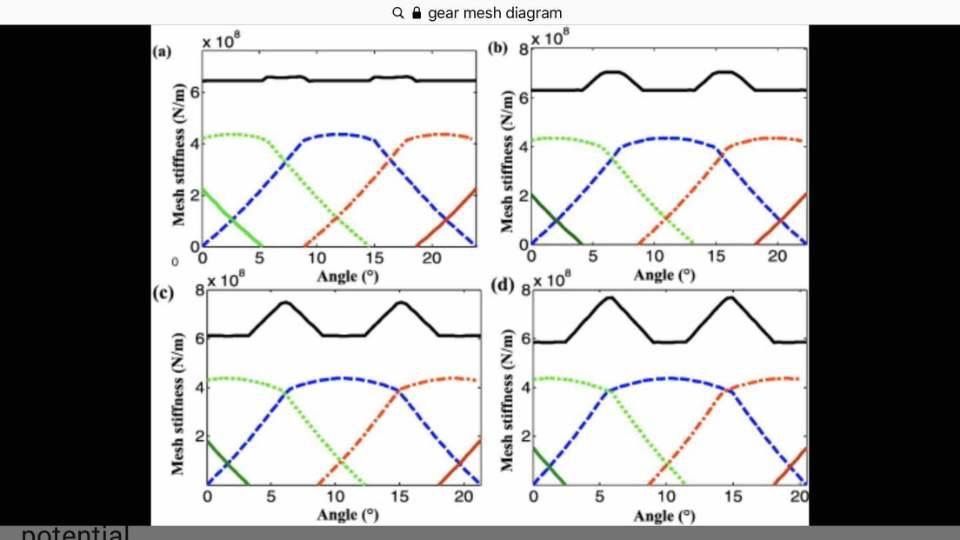
From here on the suspect went to the stiffness effect of the gear set. Some literature example of the effect on the stiffness of the tooth on rotation uniformity is seen in the figure.Basically there are on average 2 teeth continously engaged with the worm gear set. Take the blue line: this is the engagement of 1 tooth over a full rotation of the worm (as after one rev we are to the next tooth).
The green and red are the adjacent teeth that are also (partly) engaged with the blue one. Together the make a stiffness from incoming shaft to outgoing. That stiffness is the black line.
As seen the stiffness over a rotation of the worm changes two times, hence second order!
The change in stiffness has the effect that in the lower stiffness region the teeth are compressed and the outgoing shaft lacks a little behind. Moving to the stiffer part the "spring energy" is given back to the rotation and the outgoing shaft advances again.
This therefore gives a pressure fluctuation in the nozzle and results in the ripple.
The 4 diagrams show how this second order effect increases when stiffness of teeth get lower.
-
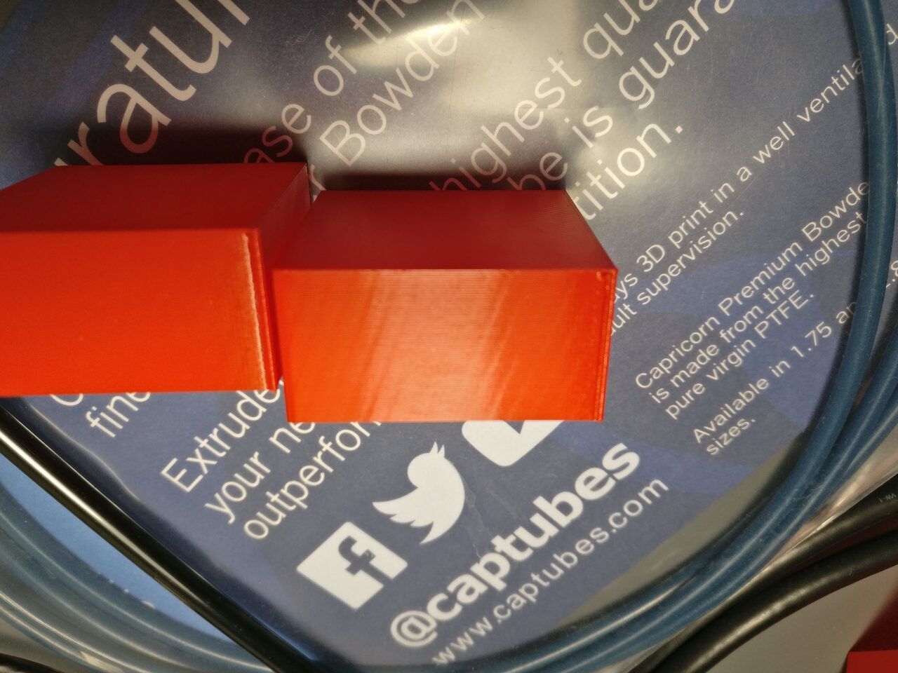
@Nuramori wow, that's very interesting. Thanks for sharing... but... I tried to print with a bondtech extruder and I get that pattern too.
I also tried to slice with different slicers and I get different results but still slant lines.
PrusaSlicer
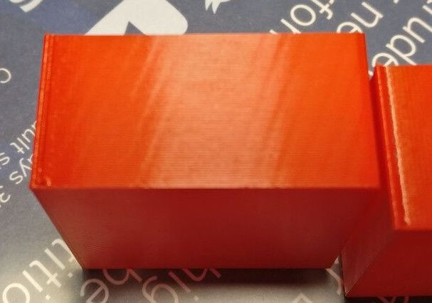
Cura
Everything seems to point to the extruder, but why I get the slant lines with every extruder I use?
@zapta yeah, I tried various layer heights and the lines indeed change.
-
I made one more test, printing the cube at 45deg to check my motion system (corexy) and the outcome is exactly the same. So it doesn't really look like a mechanical issue.
could it be that my motion system is so well tuned that it emphasizes the extruder "signature"?