Cambio elettronica
-
This post is deleted! -
l'asse z risponde come dovuto +25 si abbassa e -25 si alza anche in automatico
l'asse x e y sempre in manuale rispondono bene
ma quando vado a fare l'homing come mi aspetto l'asse z si abbassa, ma gli assi x e y se ne vann dalla parte opposta e in diagonale, i finecorsa sono dalla parte opposta cioe' asse X davanti a sx e l'asse Y davanti a dx e si spostano di 10 / 15cm poi si fermano e l'asse z va a trovare il sensore come dovuto -
nella configurazione il comando M569 P0 S1 e M569 P1 S1 li ho cambiati in M569 P0 S0 e M569 P1 S0
ma non riescono ad andare dove ci sono i stop perche' si fermano prima ed in manuale gli assi x e y vanno al rovescio -
Mi passate per cortesia una configurazione esempio per la corexy sulla movimentazione?
-
toc toc... c'e' nessuno?
-
ok chi fa da se fa x tre
-
It sounds like you're having a common problem experienced with corexy setups. I will copy and post a description of what must be done. Consider it an order of operations. It will hopefully get you on the right track. Please post if you have any questions.
https://forum.duet3d.com/topic/12676/mirrored-x-axis/9?_=1585861769573
In general, here's what you need to do to define your coordinate system. The FT5 is a little tricky because by default it puts the origin at the rear right, and has some printed grid on the bed surface (I think?) but really it's all arbitrary.
First, choose a FRONT for the printer so that when you're looking at it standing in front of it 0,0 is the front left corner, X+ goes to the right, Y+ goes to the back. This does not change because it's describing the physical layout of the printer.
Next, Measure the axis length for X and Y and enter that in your M208 command to set the axis limits. 0 at the low end (or even negative if the head leaves the bed surface to hit the endstop). This does not change because it's describing the physical layout of the printer.
Now identify where your endstops are located. They can be at the low or high end of the axis. Define them with M574. M574 X1 Y1 for low side, M574 X2 Y2 for high side, or any combo thereof. This does not change because it's describing the physical layout of the printer.
Now setup your homing movements. If the endstop is at the low end of the axis, the homing move must be negative. And vice versa. This does not change because it's describing the physical layout of the printer.
Now test the motor movement direction. If X+ moves to the right, you're good to go. If it moves left, you need to change the motor rotation for the X driver by changing the M569 S0/S1 command in config.g. Same goes for Y+ moving to the back. If you've connected the motors to their default drivers, it should be mapped like this:
M569 P0 S0 ; Drive 0 (x) goes backwards
M569 P1 S0 ; Drive 1 (y) goes backwards
M569 P2 S0 ; Drive 2 (z) goes backwards
M569 P3 S0 ; Drive 3 (e) goes backwards
If you follow those steps your printed parts will match the orientation in the slicer and won't be mirrored.You can use these steps to test your motor movement and make changes accordingly: https://duet3d.dozuki.com/Wiki/ConfiguringRepRapFirmwareCoreXYPrinter#Section_Testing_motor_movement
-
@Leblond Sorry, I'm using google translate, but I don't really understand what problem you are having. I think you say your motors are moving the X and Y axes correctly, but not towards the endstops.
First, check the X and Y axis are moving in the correct direction for CoreXY. See https://duet3d.dozuki.com/Wiki/Test_axes_or_motors_individually
Once the X and Y axis move correctly, then get the endstop configuration correct. You have the endstops set in config.g at the low end, X0 Y0.
; Endstops
M574 X1 S1 P"xstop" ; configure active-high endstop for low end on X via pin xstop
M574 Y1 S1 P"ystop" ; configure active-high endstop for low end on Y via pin ystop
Your homeall.g moves X and Y to the minimum, by moving X-335 and Y-335 towards the endstops. Is this not correct?
It may be a good idea to draw a picture to show where everything is on your printer, like this, which will help us understand where everything is without using Google translate:
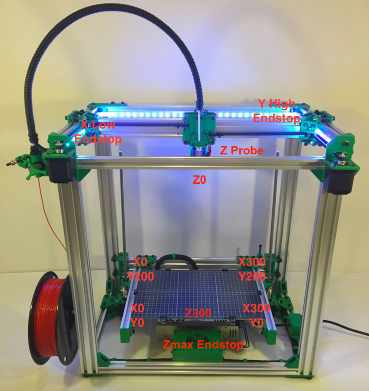
Ian
-
ti capisco ho problemi di comunicazione anche io, scrive cio' che pare a lui e adesso ne ho capito la causa, il problema e' che devi srivere senza la correzione del traduttore, ma attivarlo solo quando leggi, si ho risolto per fortuna il problema del sensore, riformattando la SD, e si ho il problema di movimentazione degli assi x e y, grazie per il momento @droftarts ci guardo e poi ti dico.
-
@droftarts una domanda, le coppie delle fasi del motore indicate sull'immagine https://duet3d.dozuki.com/Wiki/Duet_Wiring_Diagrams : cioe' 1A+1B 2A+2B sono queste, ma se nei motori le fasi non sono corrette? che problemi puo' dare?
-
Use this method to identify the phases: https://duet3d.dozuki.com/Wiki/Choosing_and_connecting_stepper_motors#Section_Identifying_the_stepper_motor_phases
-
@Phaedrux ok fatto grazie 1000
-
@Leblond if the phases are wrong, The motors won’t move and you will quickly get a message that there is a problem. As your motors are moving, I think your motors are correctly wired.
Ian
-
@Phaedrux ok allora le fasi sono corrette, un problema in meno

ho misurato gli assi e ho 352mm su x, e 352mm su y, si parla anche di valori negativi se la testina di stampa esce dal piatto
quindi nel comando M208 invece di X0 dovrei mettere M208 X-5 mm, perche' la testina e' fuori dal piatto di 5mm a sx come X min, e come X max dovrei mettere M208 X352 mm, perche' si parla di layout fisico giusto? -
That sounds correct.
-
-
; Configuration file for Duet WiFi (firmware version 3)
; executed by the firmware on start-up
;
; generated by RepRapFirmware Configuration Tool v2.1.8 on Thu Apr 02 2020 20:16:54 GMT+0200 (Ora legale dell’Europa centrale); General preferences
G90 ; send absolute coordinates...
M83 ; ...but relative extruder moves
M550 P"X5SA PRO" ; set printer nameM669 K1 ; select CoreXY mode
; Network
M552 S1 ; enable network
M586 P0 S1 ; enable HTTP
M586 P1 S0 ; disable FTP
M586 P2 S0 ; disable Telnet; Drives
M569 P0 S0 ; physical drive 0 goes backwards
M569 P1 S0 ; physical drive 1 goes backwards
M569 P2 S0 ; physical drive 2 goes forwards
M569 P3 S1 ; physical drive 3 goes forwards
M584 X0 Y1 Z2 E3 ; set drive mapping
M350 X16 Y16 Z16 E16 I1 ; configure microstepping with interpolation
M92 X80.00 Y80.00 Z800.00 E420.00 ; set steps per mm
M566 X900.00 Y900.00 Z12.00 E120.00 ; set maximum instantaneous speed changes (mm/min)
M203 X6000.00 Y6000.00 Z100.00 E1200.00 ; set maximum speeds (mm/min)
M201 X500.00 Y500.00 Z20.00 E250.00 ; set accelerations (mm/s^2)
M906 X800 Y800 Z800 E800 I30 ; set motor currents (mA) and motor idle factor in per cent
M84 S30 ; Set idle timeout; Axis Limits
M208 X-5 Y0 Z0 S1 ; set axis minima
M208 X352 Y330 Z400 S0 ; set axis maxima; Endstops
M574 X2 S1 P"! xstop" ; configure active-high endstop for low end on X via pin xstop
M574 Y2 S1 P"! ystop" ; configure active-high endstop for low end on Y via pin ystop
M574 Z1 S2 ; configure Z-probe endstop for low end on Z; Z-Probe
M558 P5 C"! zprobe.in" H5 F120 T6000 ; set Z probe type to unmodulated and the dive height + speeds
G31 P500 X0 Y0 Z2.5 ; set Z probe trigger value, offset and trigger height
M557 X60:300 Y50:300 S20 ; define mesh grid; Heaters
M308 S0 P"bedtemp" Y"thermistor" T100000 B4092 ; configure sensor 0 as thermistor on pin bedtemp
M950 H0 C"bedheat" T0 ; create bed heater output on bedheat and map it to sensor 0
M143 H0 S120 ; set temperature limit for heater 0 to 120C
M307 H0 B0 S1.00 ; disable bang-bang mode for the bed heater and set PWM limit
M140 H0 ; map heated bed to heater 0
M308 S1 P"e0temp" Y"thermistor" T100000 B4092 ; configure sensor 1 as thermistor on pin e0temp
M950 H1 C"e0heat" T1 ; create nozzle heater output on e0heat and map it to sensor 1
M143 H1 S280 ; set temperature limit for heater 1 to 280C
M307 H1 B0 S1.00 ; disable bang-bang mode for heater and set PWM limit; Fans
M950 F0 C"fan0" Q500 ; create fan 0 on pin fan0 and set its frequency
M106 P0 S0 H-1 ; set fan 0 value. Thermostatic control is turned off
M950 F1 C"fan1" Q500 ; create fan 1 on pin fan1 and set its frequency
M106 P1 S1 H1 T45 ; set fan 1 value. Thermostatic control is turned on; Tools
M563 P0 D0 H1 F0 ; define tool 0
G10 P0 X0 Y0 Z0 ; set tool 0 axis offsets
G10 P0 R0 S0 ; set initial tool 0 active and standby temperatures to 0C; Custom settings are not defined
-

-
asse X e Y tornano verso il finecorsa, fin qui tutto ok, ma il risultato non e' quello che mi aspettavo. "Foto in alto della dashboard"
-
@Leblond said in Cambio elettronica:
M574 X2 S1 P "! Xstop"; configure active-high endstop for low end on X via pin xstop
M574 Y2 S1 P "! ystop"; configure active-high endstop for low end on Y via pin ystopX2 and Y2 mean the endstops are at the high end of travel. So when homed the axis position would be the max value.
Is the X endstop on the right side? Is the Y endstop at the back?