Mesh Bed Compensation not compensating?
-
I find the same thing on my E5Plus. Even thought I do a fairly long and detailed bed process, I still find that I am having to babystep my way out of a disaster with most prints. Or worse, have to adjust the bed knobs. My regular ender5 and the CR10S (all running duets) don't seem to have this problem on such a consistent basis.
I even switched the setup to independant z motors and perform a G32, and still find I have to watch the first layer and make sure the filament goes down properly.
I perform a G28 to start, then a G32 to level the separate z axis, then do a G29 for the mesh. Still have issues. So either the G32 undoes itself, or it needs to be done after the G29...which does not make any sense.
CR10S, August 2018
Anycubic Photon S December 2019
Ender 5 Feb 2020
Ender 5 Plus May 2020
Anycubic Photon Mono X Nov 2020
~
https://3dimensiongames.com/ -
@RyanP said in Mesh Bed Compensation not compensating?:
I perform a G28 to start, then a G32 to level the separate z axis, then do a G29 for the mesh. Still have issues. So either the G32 undoes itself, or it needs to be done after the G29...which does not make any sense.
You may need to do the G32 a few times over, and you should do a single G30 at the center of the bed afterwards to redefine the Z0. Then the G29.
-
I don't think the BLTouch mount has tilt but the pin looks slightly bend to the right.
I temporarily disabled G32 in my start gcode and calibrated my axis by running against the Z endstops.
Afterwards I did G29 mesh leveling and the result was a severe tilted bed (right side was higher).
I suspect now that is has something to do with the BLTouch. Next thing I'll do is to replace the PIN and also print another more stable mount.For completion:
homeall.g
; homeall.g
; called to home all axes
;
; generated by RepRapFirmware Configuration Tool v2 on Tue Aug 06 2019 23:15:45 GMT+0200 (Central European Summer Time)
G91                     ; relative positioning
M915 X S-6 F0 H400 R0		                ; Set X axis Sensitivity
M915 Y S-1 F0 H400 R0		                ; Set y axis Sensitivity
G1 Z6 F6000 H2          ; lift Z relative to current position
G1 H1 X-255 F2600 ; move quickly to X and Y axis endstops and stop there (first pass)
G1 H1 Y-215 F2600 ; move quickly to X and Y axis endstops and stop there (first pass)
G1 X5 Y5 F6000          ; go back a few mm
G1 H1 X-255 F2600  ; move slowly to X and Y axis endstops once more (second pass)
G1 H1 Y-215 F2600  ; move slowly to X and Y axis endstops once more (second pass)
G90                     ; absolute positioning
G1 X15 Y15 F6000        ; go to first bed probe point and home Z
G30                     ; home Z by probing the bed

M915 X S3 F0 H400 R1		                ; Set X axis Sensitivity
M915 Y S3 F0 H400 R1		                ; Set y axis Sensitivity
bed.g
; bed.g ; called to perform automatic bed compensation via G32 M561 ; clear any bed transform G28 W ; home G30 P0 X35 Y100 Z-99999 ; probe near a leadscrew, half way along Y axis G30 P1 X240 Y100 Z-99999 S2 ; probe near a leadscrew and calibrate 2 motors -
I just replaced the X axis rods (one was slightly bend) and printed another BL Touch mount and replaced the pin.
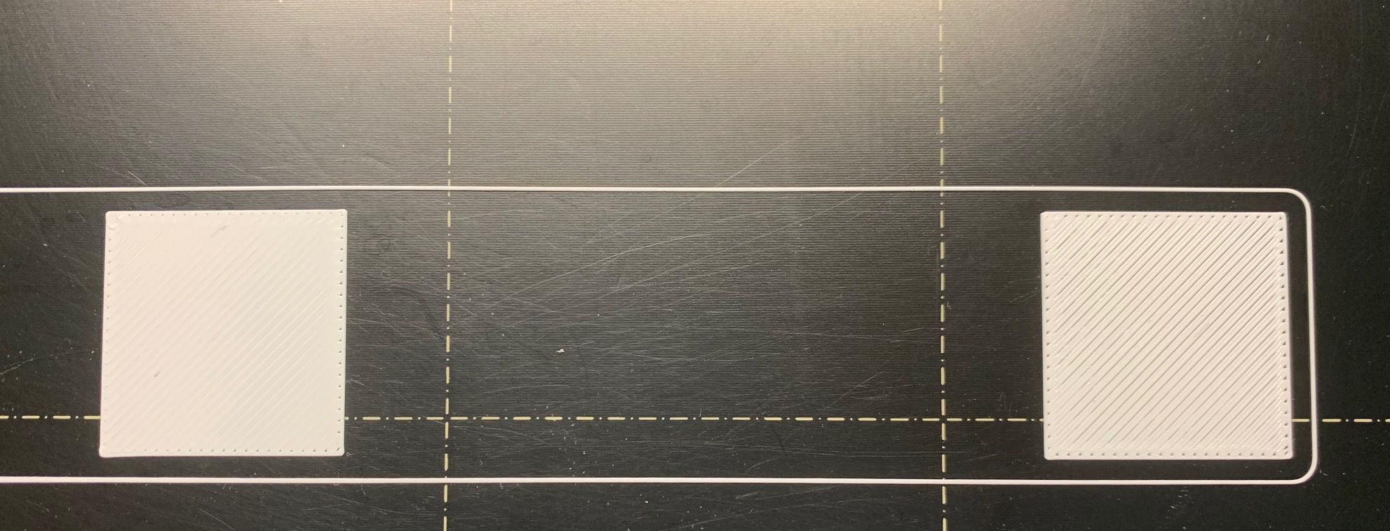
Just as before the nozzle is too far away on the right side of the bed which results in the line not sticking together.Height Map:
Print result (middle and right tile):
-
Is there some skew in the bed rail?
G1 X15 Y15 F6000 ; go to first bed probe point and home Z
G30 ; home Z by probing the bedAlso may want to move the probe point to the center of the bed.
-
You and I are experiencing the same thing, with the same brand (and model) of printer. Have you printed anything else? Like a simple box. Something with a flat surface. I print a lot of simple boxes for board games. The tend to have a number of flat solid layers. Picture a box with a open top, and solid bottom.
My layers tend to have this double line, gap, double line, gap. Just like your right hand square. I am starting to think it is a mechanical problem with Creality printers. I have three of them and this patters happens on them all. It isnt on every part, or in every area. I think a lot of it is based on the BL Touch in conjunction with a backlash or mechanical shifting of things in the X-Axis or Y-Axis.
I am currently printing a fairly intricate player box for the board game Scythe. When it is done, I will post a picture of its flat surfaces.
Keep me in the loop as to your findings as I am working through various solutions myself.
CR10S, August 2018
Anycubic Photon S December 2019
Ender 5 Feb 2020
Ender 5 Plus May 2020
Anycubic Photon Mono X Nov 2020
~
https://3dimensiongames.com/ -
Sorry for not mentioning that I‘m already using your advice to probe with 0.005 accuracy and after G32 I probe the center to determine Z=0.
New observation: after leveling the bed with a crazy 12x12 grid I can see that there is something wrong with the bad. It is very bumpy and when I print with the 12x12 mesh my Z axis can’t keep up and I have small hiccups during fast travel moves.
Next thing I do is to disassemble the Y axis, check the rods and the Y carriage for their flatness.
Hopefully I don’t have to order both.Crazy that so many thing all at once tend to break

-
I’m having a MK3s Prusa printer.
The lines got better but only with crazy accurate 12x12 mesh bed compensation. I suspect there is something terrible wrong with my y axis rods, bed or carriage or worst case: all at once. -
Update:
Y-Axis rods and the bed look fine.
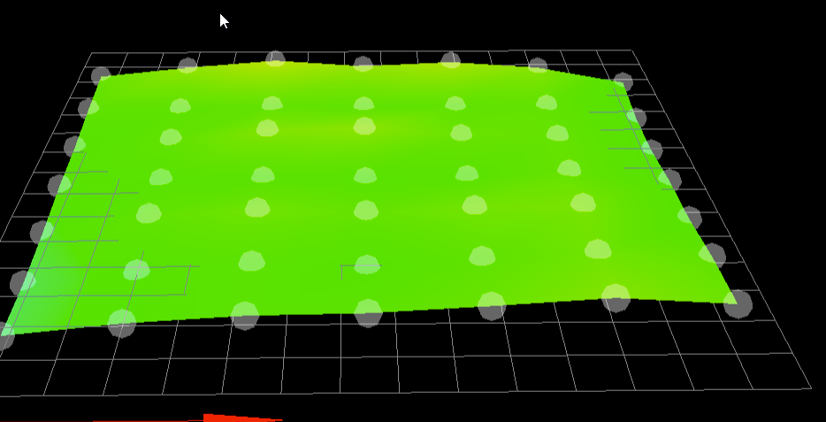
I just leveld my x axis (tilt) by slowly driving the x-axis against the Z endstops.New height map (7x7 mesh leveling, with center Z probe and 0.005 accuracy):

Print picture is the same. Left side is too close, right side too far away.
-
@Argo said in Mesh Bed Compensation not compensating?:
t is very bumpy and when I print with the 12x12 mesh my Z axis can’t keep up and I have small hiccups during fast travel moves.
Increase your Z jerk.
M566 Z24.00is very low. Try at least 60. That should solve the stutters. -
I recently had a similar issue and the problem was that the z screw was turning but the nozzle was not moving accordingly.
-
Check if your Z leadscrews are turning when moving the nozzle from left to right (using gcode. Not by hand)
-
if the screws are turning check if there is any slop in the system. If possible measure how much the nozzle moves up and down
If the z screws are not turning it I would suspect a problem with the probing itself
-
-
I did a complete frame rebuild today which improved things but it’s still not perfect level. There are parts on the bed which are good and parts which aren’t.
I’d say the inaccuracy between perfect layer and what the BLTouch measures at some spots is around 0.020mm to 0.025mm.I suspect the BLTouch measuring error comes from the fact that it is mounted too far away from the nozzle. The Y offset is -12mm from nozzle and the mount I’m using atm has even higher offset from Y.
Thereby every small inconsistency in printed parts gets magnified by the position from the BLTouch, it’s like a lever.My extruder has a slot for the Prusa PINDA Mount which merely has an offset of 2mm on the y axis.
I’ll try to configure it today and see if that helps.
I never did so because only RRF 3 supports the probe’s thermistor. -
Do give you guys an update and also for someone who might have the same issue:
Installing the probe (in my case PINDA 2) with almost no Y offset solved my probing problem.
My guess ist that any small difference (parts, rods, frame) gets amplified by the probe when the location has a big Y offset to the nozzle.I also do not recommend using "True Bed Leveling" with a cartesian printer. This could tilt the X axis which does also add an angle to the nozzle and probe. I level my X axis (tilt) by running into the Z endstops.
New working height map (almost perfect first layer)
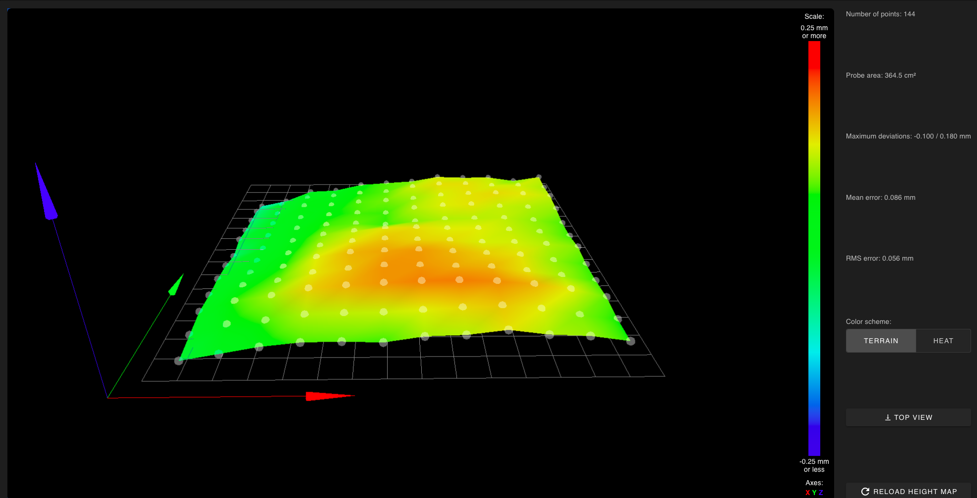
Z = 0 reference point is X10 / Y10.
And if anyone is interested in how in configured my PINDA:
; Z-Probe PINDA
M574 Z1 S2 ; Set endstops controlled by probe
M558 P5 C"^zprobe.in" I1 H0.9 F1000 T6000 A20 S0.005 ; PINDA
G31 P1000 X23 Y5 Z1.025 ; PEI Sheet Offset
;G31 P1000 X23 Y5 Z1.325 ; Textured Sheet Offset
M557 X24:221 Y10:195 P12 ; Define mesh gridThe probing is quite fast but the accuracy is quite good as the probe rarely needs more than 2 probes per point.
Next I need to figure out how to use the temperature compensation with the G31 command. -
-
Yes they are but not the overall Z offest because of the rising temperature of the probe.
-
@Argo said in Mesh Bed Compensation not compensating?:
Yes they are but not the overall Z offest because of the rising temperature of the probe.
Motivated by your posts I began testing if mesh compensation was having the expected benefits and the results have been surprising.
I've used both of my printers to print many functional parts (as opposed to decorative) but the largest of them are under 50 x 50 (mm).
I created some simple test models to try printing using the entire 150 x 100 area.
I probed the bed using a 20 x 20 grid.
The height map wasn't that bad (max deviations -0.056/+0.086, mean 0.008, RMS 0.031) although there are things I can do to improve that.
Yet even with mesh compensation enabled I did not get good bed adhesion in all areas. It was inadequate to complete the print.
I expected better results.
More testing to be done and adjustments to be made.
Frederick
-
This is exactly what I has having a while back.
My IR probe was having issues reading my printed glass bed and I switched to a regular glass. Now it is much better but because it is much flatter.
My bed has a slight lower in the upper left corner and I print nothing there as it won't stick because it is too far from nozzle (0.2mm difference)
i have this line in config-override.g that helped too:
M376 H10 ; Set bed compensation Taper