Duet3D Mainboard+Daughter board+PT100
-
Should look like this
M308 S1 P"spi.cs1" Y"rtd-max31865"
M950 H1 C"out1" T1Working on my duet 3 mainboard
-
@Carlo can you show me the hole config for heaters? just to compare with mine
-
Here you go
Ignore the bold as that was a temp test with thermistor
Eveything else is printing really well now on my setup; Configuration file for Duet 3 (firmware version 3)
; executed by the firmware on start-up
;
; generated by RepRapFirmware Configuration Tool v2.1.8 on Mon May 25 2020 14:05:35 GMT+0100 (British Summer Time); General preferences
G90 ; send absolute coordinates...
M83 ; ...but relative extruder moves
M550 P"Duet 3" ; set printer name
M665 L440.470 R231.924 H419.252 B185.0 X-0.00 Y-0.00 Z0.000 ; Set delta radius, diagonal rod length, printable radius and homed height
M666 X0.00 Y0.00 Z0.000 A0.00 B0.00 ; put your endstop adjustments here, or let auto calibration find them; Network
M552 P192.168.0.25 S1 ; enable network and set IP address
M553 P255.255.255.0 ; set netmask
M554 P192.168.0.254 ; set gateway
M586 P0 S1 ; enable HTTP
M586 P1 S0 ; disable FTP
M586 P2 S0 ; disable Telnet; Drives
M569 P0.0 S0 ; physical drive 0.0 goes backwards
M569 P0.1 S0 ; physical drive 0.1 goes backwards
M569 P0.2 S0 ; physical drive 0.2 goes backwards
M569 P0.3 S0 ; physical drive 0.3 goes backwards
M584 X0.0 Y0.1 Z0.2 E0.3 ; set drive mapping
M350 E16 I0 ; configure microstepping without interpolation
M350 X16 Y16 Z16 I1 ; configure microstepping with interpolation
M92 X160.00 Y160.00 Z160.00 E1837.00 ; set steps per mm
M566 X1000.00 Y1000.00 Z1000.00 E40.00 ; set maximum instantaneous speed changes (mm/min)
M203 X18000.00 Y18000.00 Z18000.00 E400.00 ; set maximum speeds (mm/min)
M201 X1000.00 Y1000.00 Z1000.00 E120.00 ; set accelerations (mm/s^2)
M906 X1700 Y1700 Z1700 E400 I45 ; set motor currents (mA) and motor idle factor in per cent
M84 S45 ; Set idle timeout; Axis Limits
M208 Z-0.5 S1 ; set minimum Z; Endstops
M574 X2 S1 P"io4.in" ; configure active-high endstop for high end on X via pin io4.in
M574 Y2 S1 P"io1.in" ; configure active-high endstop for high end on Y via pin io1.in
M574 Z2 S1 P"io2.in" ; configure active-high endstop for high end on Z via pin io2.in; Z-Probe
M558 P5 R0.6 C"io3.in+io3.out" H5 F1200 T6000 ; set Z probe type to effector and the dive height + speeds
G31 P500 X0 Y0 Z-0.17 ; set Z probe trigger value, offset and trigger height
M557 R170 S20 ; define mesh grid; Heaters
M308 S0 P"temp0" Y"thermistor" T100000 B4092 ; configure sensor 0 as thermistor on pin temp0
M950 H0 C"out0" T0 ; create bed heater output on out0 and map it to sensor 0
M143 H0 S120 ; set temperature limit for heater 0 to 120C
M307 H0 A122.0 C513.7 D0.5 S1.00 V24.0 B0 ; disable bang-bang mode for the bed heater and set PWM limit
M140 H0 ; map heated bed to heater 0
;M308 S1 P"temp1" Y"thermistor" T100000 B4138 ; configure sensor 1 as thermistor on pin temp1
;M950 H1 C"out1" T1 ; create nozzle heater output on out1 and map it to sensor 1
;M143 H1 S300 ; set temperature limit for heater 1 to 300C
;M307 H1 B0 S1.00 ; disable bang-bang mode for heater and set PWM limit
M308 S1 P"spi.cs0" Y"rtd-max31865" ; configure sensor 1 as thermocouple via CS pin spi.cs0
M950 H1 C"out1" T1 ; create nozzle heater output on out1 and map it to sensor 1
M143 H1 S450 ; set temperature limit for heater 1 to 450C
M307 H1 A512.3 C269.6 D3.6 S1.00 V24.0 B0 ; disable bang-bang mode for heater and set PWM limit; Fans
M950 F0 C"out9" Q500 ; create fan 0 on pin out9 and set its frequency
M106 P0 S0 H-1 C"Part Cooler" ; set fan 0 value. Thermostatic control is turned off
M950 F1 C"out7" Q250 ; create fan 1 on pin out7 and set its frequency
M106 P1 S1 H1 T45 ; set fan 1 value. Thermostatic control is turned on
M950 F2 C"out8" Q500 ; create fan 2 on pin out8 and set its frequency
M106 P2 S0 H-1 C"Berd Air" ; set fan 2 value. Thermostatic control is turned off; Tools
M563 P0 S"E3D Brass 0.4" D0 H1 F0:2 ; define tool 0
G10 P0 X0 Y0 Z0 ; set tool 0 axis offsets
G10 P0 R0 S0 ; set initial tool 0 active and standby temperatures to 0C; Custom settings
;Retraction settings
M207 S1.75 F2800 T1500 Z0.25; Miscellaneous
M501 ; load saved parameters from non-volatile memory -
@Carlo thanks, let me see what I'm missing (are you using a daughterboard to??)
-
@Reaperrhs
Yeah I have the PT100 in 0 which is the right hand terminal as you look at it are you 2 wire or 4 wire?
if 2 do you have the jumpers on behind the terminals ? -
@Carlo i have two wires, also the jumpers are in place, the two wires are connected in the right hand of the daughterboard
-
That's 0 channel, 4 connection block only 2 wire in the 2 center terminals ?
-
@Carlo yes, center terminals
-
M308 S1 P"spi.cs0" Y"rtd-max31865"
-
@Reaperrhs
There is a space before the Y M308 S1 P"spi.cs0" Y"rtd-max31865" -
@Carlo no luck so far, i have to double-check everything, also.. can you tell me whats define by the S1? because that's the only thing we have different
-
@Reaperrhs
That's the Sensor number 1 so my bed is Sensor 0 ,hot end single hot end on my setup #1 -
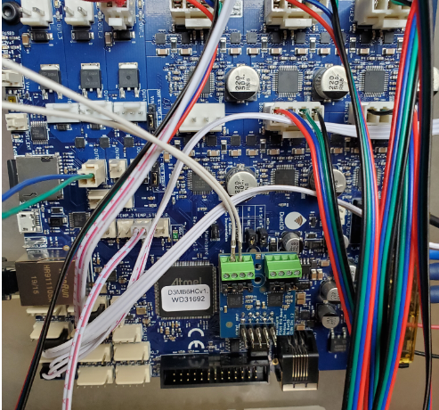
maybe attach a photo of the daughterboard and wiring as you've installed it?
Owns various duet boards and is the main wiki maintainer for the Teamgloomy LPC/STM32 port of RRF. Assume I'm running whatever the latest beta/stable build is
-
and the current heater config please
-
-
@Reaperrhs ; Heaters
M308 S0 P"spi.cs0" Y"rtd-max31865" ; configure sensor 0 as thermocouple via CS pin spi.cs0
M950 H0 C"out1" T0 ; create nozzle heater output on out1 and map it to sensor 1
M143 H0 S450 ; set temperature limit for heater 1 to 450C
M307 H0 A512.3 C269.6 D3.6 S1.00 V24.0 B0 ; disable bang-bang mode for heater and set PWM limit
M308 S1 P"temp1" Y"thermistor" T100000 B4138 ; configure sensor 1 as thermistor on pin temp1
M950 H1 C"out0" T1 ; create bed heater output on out0 and map it to sensor 1
M143 H1 S280 ; set temperature limit for heater 1 to 280C
M307 H1 B0 S1.00 ; disable bang-bang mode for the bed heater and set PWM limit
M140 H1 -
@Reaperrhs the one on the top is for my hotend, is the one with the PT100
-
Just copy and paste mine in comment your lines out ; line by line so you dont need to delete it
M308 S0 P"temp0" Y"thermistor" T100000 B4092 ; configure sensor 0 as thermistor on pin temp0
M950 H0 C"out0" T0 ; create bed heater output on out0 and map it to sensor 0
M143 H0 S120 ; set temperature limit for heater 0 to 120C
M307 H0 A122.0 C513.7 D0.5 S1.00 V24.0 B0 ; disable bang-bang mode for the bed heater and set PWM limit
M140 H0 ; map heated bed to heater 0
M308 S1 P"spi.cs0" Y"rtd-max31865" ; configure sensor 1 as thermocouple via CS pin spi.cs0
M950 H1 C"out1" T1 ; create nozzle heater output on out1 and map it to sensor 1
M143 H1 S450 ; set temperature limit for heater 1 to 450C
M307 H1 A512.3 C269.6 D3.6 S1.00 V24.0 B0 ; disable bang-bang mode for heater and set PWM limit -
@Carlo HOTEND Working Thanks!!!
-
Ok change the position of your bed thermistor on the board to 0 and you should be done.