RRF3 -> Z-Probe was not triggered during probing move
-
I have already exchanged the z-probe a few times. I have already made 20 repetitions with the homez.g and measured the trigger height, so the sensor triggers wonderfully and works very precisely (approx. 0.01mm).
It only occurs with the G29 command.
Again I have observed that with G29 it not only moves the dive height down, but the double dive height. In the dashboard, however, the "simple" dive height is shown as the Z value. that's why i think it moves twice its height and doesn't notice it.
as soon as he then carries out a test point in the G29, he has to cover twice without knowing that he drove this height before, so he claims that the z-probe does not trigger.Another dive height does not change anything, because it then moves twice without knowing it.

-
I did an extensive code-check and talk with CR3D and also didn't come to a solution.
For example: a 5-point bed-calibration works fine (a G32 (call to execute bed.g with 5x G30 in it)
Every G30 command works, but as soon as you start a G29, things start getting weird.
-
In your config.g file I see these lines:
M584 X0.2 Y0.0:0.1 U0.3 Z1.0:1.1:1.2 E0.4:0.5 ; set drive mapping
and:
M558 P5 I1 C"!io5.in" H5 F500 T12000 ; Z probe type -> Induktiv
So your Z motors are connected to the expansion board and your Z probe is connected to the main board. Unfortunately, it is a limitation of the current firmware that an endstop switch or Z probe connected to the main board cannot stop a stepper motor connected to an expansion board unless a motor connected to the main board is also moving. This was documented for endstops some time ago (at https://duet3d.dozuki.com/Wiki/Duet_3_firmware_configuration_limitations and also in the RRF 3.0 release notes at https://github.com/Duet3D/RepRapFirmware/blob/v3-dev/WHATS_NEW_RRF3.md), but unfortunately I omitted to include Z probes in those documents until recently. I apologise for that.
Possible workarounds include:
- Connect the three Z motors to stepper outputs on the main board. This is the preferred solution.
- Connect the inductive sensor to the expansion board instead of to the main board.
- Configure a 4th dummy Z motor on the main board.
Duet WiFi hardware designer and firmware engineer
Please do not ask me for Duet support via PM or email, use the forum
http://www.escher3d.com, https://miscsolutions.wordpress.com -
looking at your motor use, it looks like you are using all the drivers on the mainboard so I think you need to swap Z to the main board or the sensor to the expansion board.
-
@CR3D I was looking at your config.g file and I noticed that you have your Y-axis current set to 4200. I am not second guessing you, I was just wondering if that was correct.
-
Thank you david for your answer, that appears after a correct solution. But only as a counter question, why does a "single probe with G30" work very reliably with the Z probe on the mainboard and the motors on the expansion board?
I did repeat tests and had results of about 0.01mm with single probing ...but no matter ... it makes sense to connect both on the same board!
Yes I know this limitation... I swapped the Z-motors to the expansion board, because some days ago we had following problem, and there was no other solution to swap the Y-motors to the main board.
https://forum.duet3d.com/topic/17153/duet3-expansion-board-3hc-no-can-connection/50?_=1594149269971
With this problem at the time, I even had the endstops on the 3HC board and it still didn't work.
That is why the three Z-axes are now on the expansion board. This made me forget to put the Z-probe from the main board onto the expansion board.
I just tried to test it, hoping to find the solution here. I put the Z-probe on the PIN C "^! 1.io5.in".
; Z-Probe
M558 K0 P5 C"^!1.io5.in" H5 F400 T10000 ; Z probe type -> Induktiv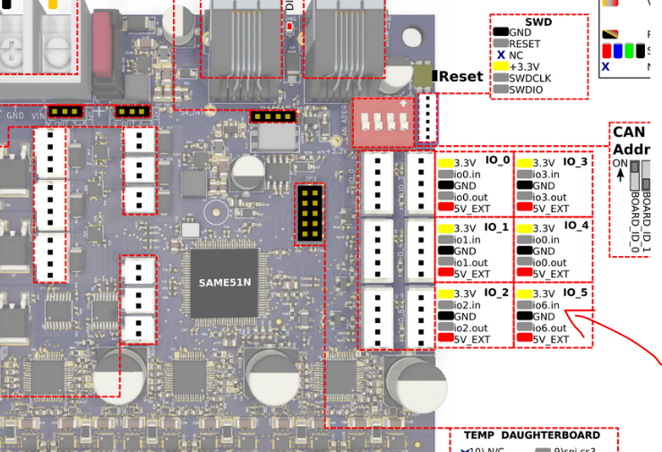
As soon as I plug in the z-probe here and adjust the config, the Z-probe disappears from the dashboard and with a probe command the error message appears that the Z-probe could not be found.
As soon as I plug it back into the main board, it appears again!
what can be the problem here?
Plugging the Z motors onto the mainboard is not an option due to the homing error mentioned above for the Y axis.
Or would it be possible to have one motor (i.e. 1x Y and 1x Z) on the main board and the others on the expansion board?
@Skimmy special thanks for the detailed examination of the code the last days
")
@Karma : I use NEMA 23 motors at the y-axis and they need this current
many thanks for the numerous answers! I hope, we find a solution
Regards Christian (CR-3D)
Christian from CR-3D
Homepage:
www.cr-3d.deFacebook:
https://www.facebook.com/cr3d.officialOur Discord Server
https://discord.gg/SxRaPNuRdAThingiverse Profile:
https://www.thingiverse.com/cr-3d_official/about -
@CR3D Ahh, that makes perfect sense now. Thank you for that answer.
I would live to get my hands on a Duet 3, but my wife would kick my rear end if I spent anymore money on my printer right now. The Duet 3 board has so many more options then any board I have every seen. It's truly a work of art.
-
I even tested it now to always place at least one motor on the respective axis (i.e. a motor with the 3 z-axes on the mainboard and one of the two Y-axes on the expansion board) and map it correctly in the config. But this didn't work at all, not all axles drive clean here!
Why doesn't the Z-Probe work on the expansion board? That would be the easiest way ...?
-
@CR3D said in RRF3 -> Z-Probe was not triggered during probing move:
As soon as I plug in the z-probe here and adjust the config, the Z-probe disappears from the dashboard and with a probe command the error message appears that the Z-probe could not be found.
One of the listed limitations is that a Z probe connected to an expansion board must be type 8 or type 9. So change the P parameter in your M558 command from P5 to P8.
Duet WiFi hardware designer and firmware engineer
Please do not ask me for Duet support via PM or email, use the forum
http://www.escher3d.com, https://miscsolutions.wordpress.com -
Thank you... also my mistake... sorry
But now to my test result:
As usual, I connected all Z-motors to the expansion board and also the Z-probe to the expansion board.
See config:
; Configuration file for Duet 3 (firmware version 3)


; General preferences
G90            ; send absolute coordinates...
M82            ; and absolute extruder moves
M550 P"I444-S" ; set printer name

; Network
M552 S1        ; enable network
M586 P0 S1     ; enable HTTP
M586 P1 S0     ; disable FTP
M586 P2 S0     ; disable Telnet

; Drives

M569 P0.0 S1   ; physical drive 0.0 goes forwards Y0
M569 P0.1 S0   ; physical drive 0.1 goes forwards Y1
M569 P0.2 S0   ; physical drive 0.2 goes forwards X
M569 P0.3 S0   ; physical drive 0.3 goes forwards X1 (U)
M569 P0.4 S0   ; physical drive 0.4 goes backwards E0
M569 P0.5 S0   ; physical drive 0.5 goes backwards E1

M569 P1.0 S1   ; physical drive 1.0 goes forwards Z0
M569 P1.1 S1   ; physical drive 1.0 goes backwards Z1
M569 P1.2 S1   ; physical drive 1.0 goes forwards Z2


;New Mapping
M584 X0.2 Y0.0:0.1 U0.3 Z1.0:1.1:1.2 E0.4:0.5  ; set drive mapping

M350 X16 Y16 U16 Z16 E16:16 I1  ; configure microstepping
M92 X80.00 Y35.56 U80 Z1600 E415:415 ;set steps per mm
M566 X300 Y300 U300 Z12 E300:300   ;set maximum instantaneous speed changes (mm/min)
M203 X60000 Y60000 U60000 Z1000 E9000:9000      ;set maximum speeds (mm/min)
M201 X1000 Y1000 U1000 Z200 E1000:1000            ;set accelerations (mm/s^2)
M906 X1400 Y4200 U1200 Z1500 E1000:1000 I30  ;set motor currents (mA)
M84 S30             		    ; Set idle timeout

; Axis Limits
M208 X0 Y0 U91 Z0 S1     ; set axis minima
M208 X460 Y500 U551 Z420 S0         ; set axis maxima

; Endstops
M574 X1 S1 P"!io1.in" ; active-high endstop for low end on X via pin io0.in
M574 U2 S1 P"!io0.in" ; active-high endstop for high end on U via pin 1.io1.in
M574 Y2 S1 P"!io2.in" ; active-high endstop for high end on Y via pin 1.io2.in
M574 Z1 S2

; Z-Probe
M558 K0 P8 C"^!1.io5.in" H5 F400 T10000 ; Z probe type -> Induktiv

;Z-Probe Piezo
;M558 P5 C"!io3.in" R1.0 K0 H5 F200 T6000 ; Z probe type -> Piezo
;M558 P5 C"!io4.in" R1.0 K1 H5 F200 T6000 ; Z probe type -> Piezo
;G31 K0 P100 X0.0 Y0.0 Z-0.30
;G31 K1 P100 X0.0 Y0.0 Z-0.30

M557 X80:330 Y30:310 P04:04      ; define mesh grid

; Heaters
M308 S0 P"temp0" Y"thermistor" T100000 B4092          ; configure sensor 0 as thermistor on pin temp0
M950 H0 C"out0" T0                                    ; create bed heater output on out0 and map it to sensor 0
M307 H0 B0 S1.00                                      ; disable bang-bang mode for the bed heater and set PWM limit
M140 H0                                               ; map heated bed to heater 0
M143 H0 S120                                          ; set temperature limit for heater 0 to 120C

M308 S1 P"temp1" Y"thermistor" T100000 B4725 C7.06e-8 ; configure sensor 1 as thermistor on pin temp1
M950 H1 C"out1" T1                                    ; create nozzle heater output on out1 and map it to sensor 1
M307 H1 B0 S1.00                                      ; disable bang-bang mode for heater  and set PWM limit

M308 S2 P"temp2" Y"thermistor" T100000 B4725 C7.06e-8 ; configure sensor 2 as thermistor on pin temp2
M950 H2 C"out2" T2                                    ; create nozzle heater output on out2 and map it to sensor 2
M307 H2 B0 S1.00                                      ; disable bang-bang mode for heater  and set PWM limit

; Fans

M950 F0 C"out4"                                   ; create fan 2 on pin out4 and set its frequency
M106 P0 S0 H-1                                        ; set fan 2 value. Thermostatic control is turned off
M950 F1 C"out5"                                  ; create fan 3 on pin out5 and set its frequency
M106 P1 S1 H2:1 T50                                   ; set fan 3 value. Thermostatic control is turned off

; Tools
M563 P0 S"Links" D0 H1 F0  ; define tool 0
G10 P0 X0 Y0 Z0 S0 R0        ; set tool 0 axis offsets
M563 P1 S"Rechts" D1 H2 X3 F0   ; define tool 1
G10 P1 Y0 U0 Z0 S0 R0        ; set tool 1 axis offsets


; Custom Safety Settings

; Open Door Switch

M950 J0 C"!1.io0.in"
M950 J1 C"!1.io1.in"
M950 J2 C"!1.io2.in"

; Emergency Stop
M950 J3 C"!1.io3.in"


M581 T0 C"1.io3.in"  S0 C0		;trigger #2 (calls trigger0 -> Emergency-Stop)
M582 T0

; LEDs
; Farbe Blue
M950 F2 C"out3" Q500  ; create fan 3 on pin out5 and set its frequency
M106 P2 S119     ;set fan 3 value. Thermostatic control is turned off
; Farbe Red
M950 F3 C"1.out0" Q500  ; create fan 3 on pin out5 and set its frequency
M106 P3 S0     ;set fan 3 value. Thermostatic control is turned off
; Farbe Green
M950 F4 C"1.out1" Q500  ; create fan 3 on pin out5 and set its frequency
M106 P4 S117     ;set fan 3 value. Thermostatic control is turned off
; Farbe White
M950 F5 C"1.out2" Q500  ; create fan 3 on pin out5 and set its frequency
M106 P5 S0     ;set fan 3 value. Thermostatic control is turned off


; Miscellaneous

M501          ; load saved parameters from non-volatile memory

T0            ; select first tool
M400

M572 D0 S0.03
My config-override:
; config-override.g file generated in response to M500 at 2020-07-06 20:53
; This is a system-generated file - do not edit
; Heater model parameters
M307 H0 A53.3 C44.6 D1.1 S1.00 V23.9 B0
M307 H1 A967.6 C371.4 D5.4 S1.00 V23.7 B0
M307 H2 A340.0 C140.0 D5.5 S1.00 V0.0 B0
; Probed tool offsets
G10 P0 X0.00 Y0.00 Z0.00 U0.00
G10 P1 X0.00 Y0.00 Z-0.13 U0.00

G31 K0 P500 X40.0 Y30.0 Z1.40

; Workplace coordinates
G10 L2 P1 X0.00 Y0.00 Z0.00 U0.00
G10 L2 P2 X0.00 Y0.00 Z0.00 U0.00
G10 L2 P3 X0.00 Y0.00 Z0.00 U0.00
G10 L2 P4 X0.00 Y0.00 Z0.00 U0.00
G10 L2 P5 X0.00 Y0.00 Z0.00 U0.00
G10 L2 P6 X0.00 Y0.00 Z0.00 U0.00
G10 L2 P7 X0.00 Y0.00 Z0.00 U0.00
G10 L2 P8 X0.00 Y0.00 Z0.00 U0.00
G10 L2 P9 X0.00 Y0.00 Z0.00 U0.00
now i have carried out another test.
First home home all axes and then G29.
And here unfortunately the same result again! The first probe point at the corner was fine... the second one causes following error
As already described above, this can only happen after several probe points!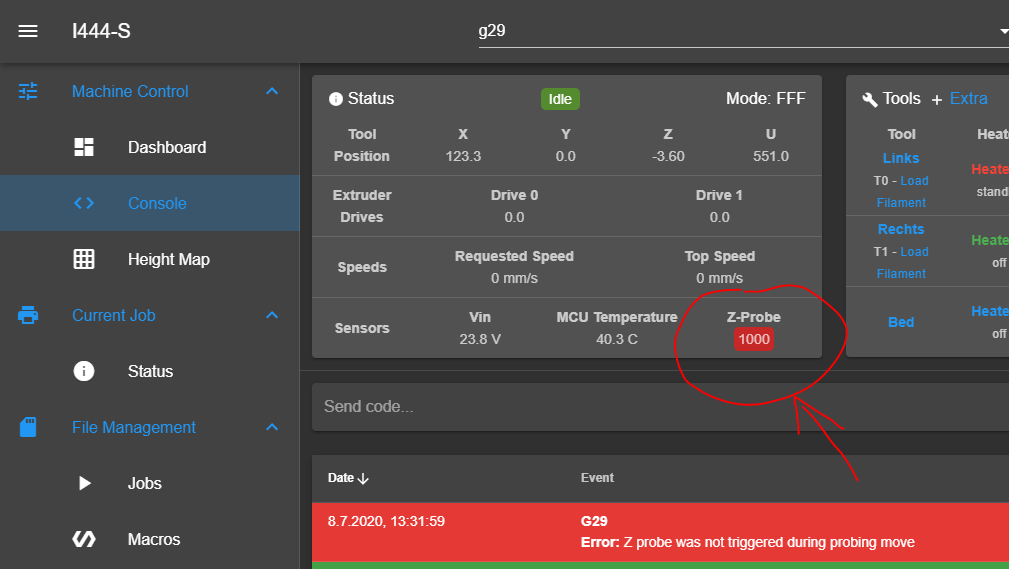
please note as always the probe is triggered even though it causes the error!

So that was not the solution to the problem ... are there any other solutions?
-
@CR3D I’m a bit late to the game but I’m your very first post you showed two codes, one for RRF3 and the other for RR2. The probe heigh value in RRF 3 is 20mm and in RRF 2 it was only 7mm. That would explain why it is moving a greater distance. No?
-
-
@dc42 how can we go on?????
-
I'm trying to replicate this now.
Duet WiFi hardware designer and firmware engineer
Please do not ask me for Duet support via PM or email, use the forum
http://www.escher3d.com, https://miscsolutions.wordpress.com -
I can see the problem. After a successful probing move, the Z motors are moving too far to get back up to the dive height, as if they had made the full Z movement and the move had not been stopped by the probe triggering. I think I know why this is happening, and unfortunately it's not an easy fix in firmware because in order to get accurate probing, additional CAN messages will have to be sent from the expansion board.
So in order to get you a solution quickly, I would like to revisit the problem you had originally when the Y and U axes were driven from the expansion board, as you described at https://forum.duet3d.com/post/162067, and solve that one. Please can you reconfigure your system with the Z motors and Z probe connected to the main board, and Y and U motors connected to the expansion board. Also connect the Y and U endstop switches to the expansion board. Then please test homing the U axis and post what happens. I suggest you start another thread do describe the results - I will be watching for it. When we have U axis homing working, then we'll work on Y axis homing.
Duet WiFi hardware designer and firmware engineer
Please do not ask me for Duet support via PM or email, use the forum
http://www.escher3d.com, https://miscsolutions.wordpress.com -
@dc42 Thank you!
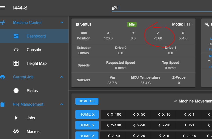
Here is another picture of the second probe point after which the error message comes.
Here the dash shows that we are already at Z-3.6mm.
The nozzle is still in the air.
@Skimmy -> you saw it too ...
")
And here is a video:
Please note in the video ... after homing (G28) the nozzle is at 6.4mm (5mm Dive Height + 1.4mm Z-Offset). thats alright. When I drive to Z0, the nozzle is exactly over the bed. It all fits!
With the G29 command, it moves to the first measuring point, everything works perfectly here (the dive height is 5mm). If he then goes to the second measuring point, the dive height is 10mm! Therefore, it then displays a negative Z-value (-3.6mm) in the error message (Z-Probe not triggered during probing move)
Note that the nozzle is still in the air and the sensor could not even trigger (since it is too far from the print bed)
-
Ok .. good that we finally found the bug!
Too bad it is not so easy to solve now ... Ok I will try to put everything back to the old SETUP and hope we can find a quick solution here ... thank you in advance