Duet 2 Ethernet and SBC
-
@arhi said in Duet 2 Ethernet and SBC:
@deadwood83 why solder to board instead plugin in to the header?
presumably because wifi boards don't have headers?
-
@bearer wifi boards you have to desolder the board right? so if you do that you can solder on the 2 headers thats easier than removing the esp module
 ...
... -
@arhi said in Duet 2 Ethernet and SBC:
@bearer wifi boards you have to desolder the board right?
simply disabling it in either RRF or WiFi firmware seems to work, but can't say I've done a ton of testing (there is a thread with a pogo pin thing to slap on top of existing wifi module and worked for the limited testing i did)
-
@bearer ah, that's cool then
") ... I dislike wifi in general so never even tried the duet2wifi board all my duet's are eth ... anyhow it's rather easy to solder a header on this board too so not a biggy even as is it is very useful
... I dislike wifi in general so never even tried the duet2wifi board all my duet's are eth ... anyhow it's rather easy to solder a header on this board too so not a biggy even as is it is very useful -
@arhi said in Duet 2 Ethernet and SBC:
anyhow it's rather easy to solder a header on this board too so not a biggy even as is it is very useful
true, but the headers holes are covered by the wifi module which is probably not for everyone to remove.
-
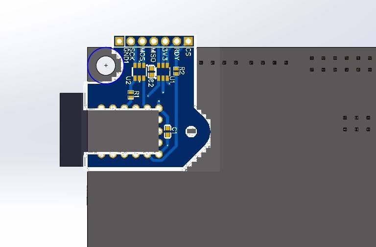
It is version agnostic. It is attached to the back of the board, so it works with both ethernet and wifi versions. No desoldering required, only attaching pins to the Pi header. I will publish the public EasyEDA links once I verify all my measurements in KiCad.
EDIT:
-Updated image to be proper scaling.
-Created non-hollow version with plated through-holes for ethernet users who want to stick it on the headers
-License is CERN open hardware, feel free to commercialize it if anybody feels so motivated.
-Strengthened top section, re-scaled text, verified clearance against paneldue header, extended bottom of board to index against duet mainboard.
-NO DESOLDERING NECESSARY
-Updated grounding to star/bus ground patternI took the plunge.
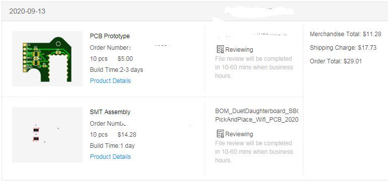
I will keep 5 for me. The others can go to homes in the US at the cost of a flat rate envelope.
-
I think I may have messed up in my design.
@T3P3Tony I have a question about the SBC conn on the duet 3 v1.01. On my little breakout I put a 470-Ohm in series with the input buffers on SCLK and only just realized (after ordering some) that your placement of the 470 was NOT on the clock line but rather on PC23/IO_7_OUT. Looking at TI's guidelines for matching a series damping resistor: https://www.ti.com/lit/an/scba012a/scba012a.pdf
Assuming worst-case scenario, at max output current for the SN74LVG2G34 (12mA) we get Irms of ~8mA
Using PCBWay's trace impedance tool shows a line impedance of roughly 105-Ohm for 2 layer FR4 1.6mm 1-Oz copper PCB using the trace width of .61mm
My worry is that the 470-Ohm resistor will provide too much dampening and round off the waveform peaks too much since SCK on the daughterboard lives at the termination rather than origination (or could this be considered the origination due to the amount of PCB the signal must travel?). Do you think this is a valid worry, or should it be OK with the resistor there at the current speed of 8MHz?
Considering other solutions to this point involved some wires with crimped/socketed resistors, and one instance of a breadboard, am I just overthinking it now?
-
@deadwood83 said in Duet 2 Ethernet and SBC:
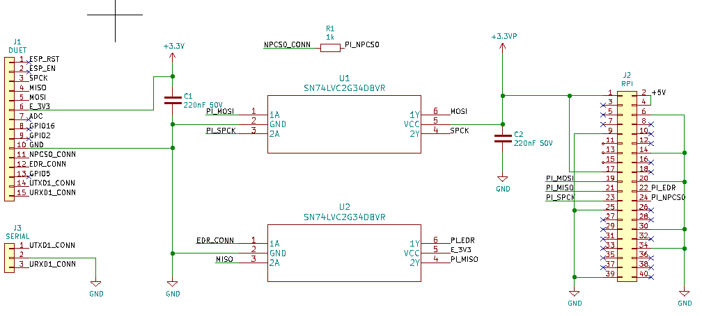
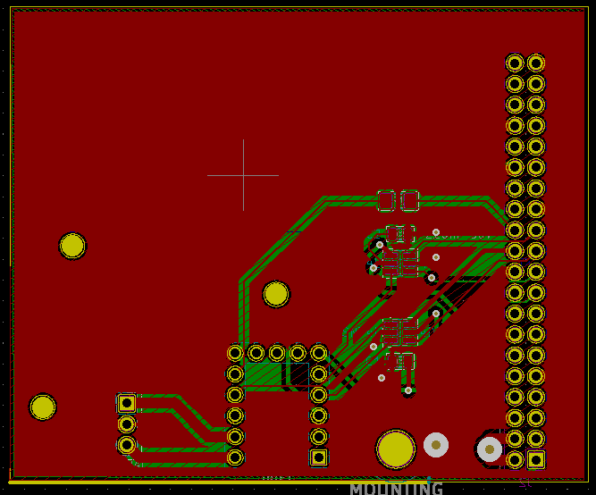
The schematics/PCB
awesome
thanks
Did you made this in kicad and exported to easyeda or you made it directly in easyeda. I can redraw it in kicad but if you already have it in kicad it would save me some time -
@deadwood83 Cool design. I use a would use a similar one but with an integrated 5V DCDC converter to power the raspberry. Otherwise you need an external one which is not so pretty and easy to use.
I also integrated the same pin layout as on the raspberry to use a simple ribbon cable.
But actually the firmware is the first thing which need to be fixed
-
@deadwood83 Wrote you a PM
-
@deadwood83 said in Duet 2 Ethernet and SBC:
2 layer FR4 1.6mm 1-Oz copper PCB
4 layer and 2 Oz for the Duets
-
@deadwood83 R100,R101,R105 on the SPI lines on the Duet 2 side are 47R. There are relatively short lines from those resistors to the relevant pins. External copper is 2Oz and these are 0.25mm traces. internal solder is 1Oz, same trace width.
Where we use those buffers on the Duet 3 we don't have series resistors in the circuit as well as the buffers so the 470R is probably unnecessary
-
@arhi said in Duet 2 Ethernet and SBC:
@deadwood83 said in Duet 2 Ethernet and SBC:
The schematics/PCB
awesome
thanks
Did you made this in kicad and exported to easyeda or you made it directly in easyeda. I can redraw it in kicad but if you already have it in kicad it would save me some timeI made it in EasyEDA. I keep trying to go to KiCAD but snap to grid just... drives me completely insane. I wager that will become pretty much mandatory once I graduate beyond 2-layer.
@smoki3 said in Duet 2 Ethernet and SBC:
@deadwood83 Cool design. I use a would use a similar one but with an integrated 5V DCDC converter to power the raspberry. Otherwise you need an external one which is not so pretty and easy to use.
I also integrated the same pin layout as on the raspberry to use a simple ribbon cable.
But actually the firmware is the first thing which need to be fixed
I fear that any buck which would fit on a reasonable sized board would not be up to snuff. I have seen LMs and MP bucks burn Pi's faaaar too many times to feel comfortable putting one in one of my designs. Also, when you put power to the pi through GPIO it is my understanding that it bypasses a significant section of input protection. I will stick to $10 10A converters. Much safer to run 10-30% of a very cheap piece of kit's rating IMO when it has questionable pedigree.
RE: Ribbon cable; My personal preference is to twist MISO/MOSI lines from individual conductors. CS has a buffer resistor near the node end (and doesn't have the sensitivity of the other 3) and 3v3_Pi isn't near the SPI pins anyway. Plus anybody soldering to a 3d printer controller probably has some dupont connectors #DiabloEternal
RE: Firmware fix; from the RF3.2 excel spreadsheet -
Duet+SBC support
Duet 2 SBC support Done

@PCR said in Duet 2 Ethernet and SBC:
@deadwood83 Wrote you a PM
Replied
@bearer said in Duet 2 Ethernet and SBC:
@deadwood83 said in Duet 2 Ethernet and SBC:
2 layer FR4 1.6mm 1-Oz copper PCB
4 layer and 2 Oz for the Duets
Understood, my impedance calcs were based on my cheap PCB though. I am not worried about the Duet circuitry since it comes from more capable designers than I
@T3P3Tony said in Duet 2 Ethernet and SBC:
@deadwood83 R100,R101,R105 on the SPI lines on the Duet 2 side are 47R. There are relatively short lines from those resistors to the relevant pins. External copper is 2Oz and these are 0.25mm traces. internal solder is 1Oz, same trace width.
Where we use those buffers on the Duet 3 we don't have series resistors in the circuit as well as the buffers so the 470R is probably unnecessary
Thanks Tony. I have updated my PCB layout to remove that and will put a simple solder bridge once my PCBs arrive. Being 0403 size, it could probably be bridged with a c-store lighter! (I will use my T12 station)
-
@deadwood83 said in Duet 2 Ethernet and SBC:
I keep trying to go to KiCAD but snap to grid just
I'm still getting used to KiCAD since I don't have access to licenced Altium any more and since I don't allow "cured" software on my computers had to find alternative and KiCAD is kinda best I managed to find.The grid thing .. what I do is I make my own set of trace widths and my own grid values and then I switch between them ... there's probbly a better way to do it but...
I wanted to steal from your design the dimensions - position of headers vs that hole on top and the screw and ... but since I'm doing a push-on daughterboard (I used eth modules so remove eth board, plug in this one) with 5A DCDC and maybe some leds I might actually don't need to worry about positions...
-
There is a PCB in the EasyEDA link which is closed off and with through-holes for the ethernet board for those who want to just stick on some headers and go. The components are low-profile so it will fit top or bottom.
The only things you would need to add are 5v buck and some LEDs. Look in the EasyEDA project for ethernetPCB and you will find it there, ready for you.

-
@deadwood83 said in Duet 2 Ethernet and SBC:
RE: Firmware fix; from the RF3.2 excel spreadsheet -
Duet+SBC support
Duet 2 SBC support DoneUnfortunately this support is currently limited to Duet 2 only, i.e. no DueX2/DueX5 connected.
EDIT: the above is still considered a preliminary limitation and it is being worked on to get this resolved.
Explicitly pulling the ESP_Enable line down (for a still present Wifi module) should be added to firmware soon.
-
@deadwood83 seen that but I want to make it different (a pcb that will plug directly into rpi + duet), but looks like easier to measure distance of the hole from the header than reworking the easyeda project ... I'll share the project when I make it
-
@arhi said in Duet 2 Ethernet and SBC:
but looks like easier to measure distance of the hole from the header than reworking the easyeda project .
the kicad sources for the duet gives you all the measurements, with the measurement tool in kicad? I used that to print a piece to glue some dupont headers to and keep the holes for the stand-offs.
-
@bearer said in Duet 2 Ethernet and SBC:
the kicad sources for the duet
HAAHA I did not see the tree from the forest ... thanks, I was trying to move the tiny board to kicad, danced with calipers... loading kicad source of the duet2eth board did not at any point come to mind
thanks, that solves my problem 100% -
I went with a WAAAAAY bigger board to avoid using any cables. Something like this .. I kept all 3 mount holes for the wifi board, expanded the board outside of the duet pcb so that this board can plug directly, in the same time, into duet and into rpi so no cables .. I also added a header for RX/TX for uart1 on the duet since it's not used any more might be useful for cnc pendant or second screen or ..
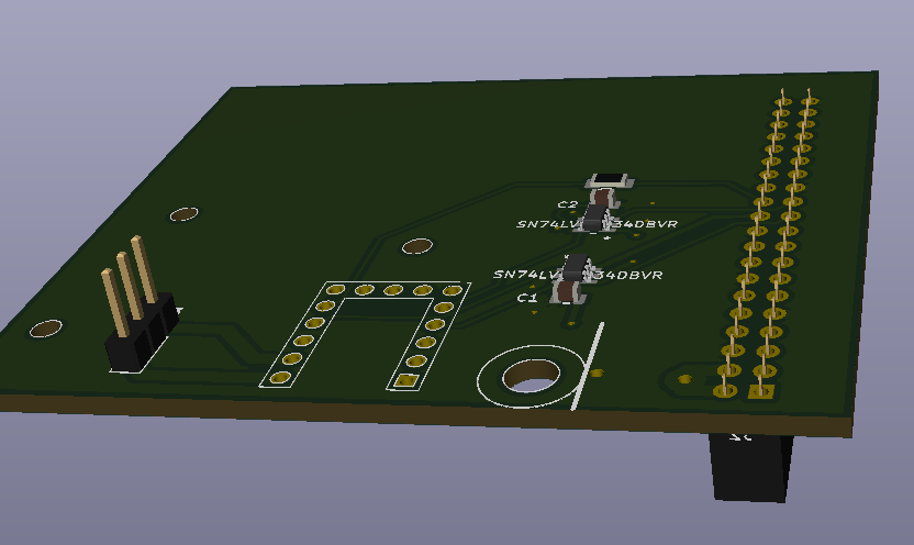
I still suck at kicad big time but this should work .. kicad files who wanna play, maybe make better