leadscrew vs ballscrew
-
My printer has a 700 mm long, belt-lifted Z axis. It uses a 30:1 worm gear reducer that stops the bed from moving when the Z motor power is cut- you don't need to worry about brakes to stop the bed from slamming into the bottom of the printer. The motor and gearbox come as a unit, so you don't have to mess around (much). It uses a keyed 8mm shaft (that's the messing around part). It has a NEMA23 motor driven directly by the Duet board driver. I run the motor at about 1A and it still has plenty of grunt to lift the 3.5 kg bed plus 4 kg of print. Top speed is 15 mm/sec in my printer.
The printer doesn't use any auto leveling and Z=0 is set by an optical endstop and screw. The bed is on a kinematic mount and it stays level once set manually using the manual bed leveling assist built into RRF. I don't have to adjust it, ever, unless I take apart the Z axis to make a modification (last time was maybe 8 months ago).
Here's the worm gear drive:
https://www.ebay.com/itm/Rino-Motorized-Rotary-Table-Stage-CNC-4th-Axis-Sherline-Milling-Engraver-Router/191714031261?epid=711126295&hash=item2ca30bf69d:g:A7UAAOSwPhdVB2f0Some pictures
[UMMD Z axis ](https://drive.google.com/file/d/17K20nkb95RXOf_OFrKNdmo2UW4CKLLPX/view?usp=sharing, https://drive.google.com/file/d/1FRbF3AvW42yLIC7u1Vhlc_W56gK6790Q/view?usp=sharing, https://drive.google.com/file/d/1p1Pav9lCuDMh7R7oA3b6llfytrZws9__/view?usp=sharing) -
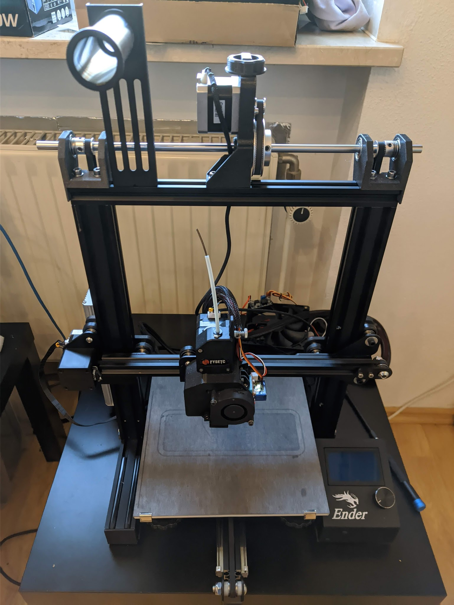
i just converted my ender 3 to belt driven
-
Buy quality parts. Not cheap parts.
-
@Veti Do you have a part list and files for it?
")
-
https://github.com/kevinakasam/BeltDrivenEnder3
i modified the setup a bit. i used the metal toothed pulley instead of the printed one. because of that i needed to raise the height by about 5mm.
-
@Dad003 I tried cheap, used, super cheap and high quality 1605 ballscrews and they were all better (even the cheap-used) than high-quality acme leadscrew, and next-level stuff compared to PRC delivered acme leadscrews. Now, high quality acme screws are usually good enough for Z but if you can afford and have room to place ballscrews - they are worth it :). Now I never tried any of these small ones like 1204, 1605 is the smallest one I ever tried but I guess small ones are decent. The only important issue with any of the cnc movable parts from PRC - you have to open the nuts, remove all the bearings, clean all the bearings and the nut, check if you have "not shiny" bearings and replace them - ideally, replace ALL bearings with decent ones from hardware store (they are cheap), clean, "wash" (W60 is ideal imho for that), lubricate again with proper lubricant.
belt driven Z is great option but have it's own set of drawbacks... if you introduce gearing to get precision and torque those gearing need to be super high quality or it will introduce worse issues that what you started with
-
@matt3o said in leadscrew vs ballscrew:
you have very long leadscrews, I find that it's very difficult to source straight medium quality leadscrews longer than 300mm. You may try with 10mm leadscrews that are relatively easy to find.
10mm dia with a 2mm lead/pitch, works well.
Ian @deckingman has a nice video covering lead screws if you want a little education.
As for sourcing straight lead screws dont even try to, a pair of roller v blocks, a dial indicator and a heat source then straighten to whatever tolerance you wish.
I got a set of 600mm long ones to under a thou of run out in about 15 minutes on each one
-
@CaLviNx said in leadscrew vs ballscrew:
10mm dia with a 2mm lead/pitch, works well.
@omni replaced his on D9 with 10x2 acme and they came pretty darn straight and work awesome
I got a set of 600mm long ones to under a thou of run out in about 15 minutes on each one
how the ^#%$^#&^%# you do it
 ... I tried to straighten few 8x2 40cm and more I tried worse they got
-
find the high spot with the dial indicator, heat the high spot with a pencil torch, cold quench with a wet cloth, simple, mind you i have a few years of experience of straightening hydraulic rods offshore.
-
@CaLviNx said in leadscrew vs ballscrew:
Ian @deckingman has a nice video covering lead screws if you want a little education.
For the sake of completeness, here is a link to the aforementioned video https://www.youtube.com/watch?v=o_0xdrKUYVU
-
@CaLviNx said in leadscrew vs ballscrew:
find the high spot with the dial indicator, heat the high spot with a pencil torch, cold quench with a wet cloth, simple, mind you i have a few years of experience of straightening hydraulic rods offshore.
I tried that technique too (using proxxon butane torch) ... same as with "pressing it between two blocks" .. I'm just not made for that
.. -
@arhi 10x2 ACME leadscrews I got were very straight and solved my heavy dual z-axis falling problem - but they are a pain to tune ideally, especially with dual linear rails on each side.... everything needs to be aligned within a fraction of a mm or you'll have rail grinding and artifacts in the print.... but if you do it properly it solves most of the problems.
-
@omni said in leadscrew vs ballscrew:
@arhi 10x2 ACME leadscrews I got were very straight and solved my heavy dual z-axis falling problem - but they are a pain to tune ideally, especially with dual linear rails on each side.... everything needs to be aligned within a fraction of a mm or you'll have rail grinding and artifacts in the print.... but if you do it properly it solves most of the problems.
The purpose of a leadscrew & nut (in the context of a 3d printer) is to convert a rotational action from the motor into a linear vertical raising/lowering action, therefore you only need to concern yourself about that, the major problem I see is people forgetting that and trying to constrain the nut and or the leadscrew too much, if you design the system so as the leadscrew nut is able to "float" along the X & Y planes then you do not need to get too anal, the only reall alignment required is to make sure all the rails are vertical, and alignment shouldnt be he job of the leadscrew to worry about, its only concern is regards to the up or down motion.
The weight of the bed/bed frame pushes downwards against the nut in the vertical Z plane keeping everything where it needs to be when going down, when the leadscrew is rotating it is pushing against the weight and that keeps everything in place on the upwards stroke. too many people try to over design and over think these simple machines.
-
One of the biggest differences you are likely to see going from cheap leadscrews to cheap ballscrews is CPE.
Cumulative Pitch Error.
Or the thing that makes your printer produce objects that are the wrong height.
Cheap leadscrews can be off by 3mm in 300mm.
Even cheap ballscrews are normally in the sub-mm range.
Expensive leadscrews can be just as good.
Expensive (ground, as opposed to rolled) ballscrews will be in the <0.01/300mm sort of range. Depending on how much you want to spend. Although if you want to worry about that kind of precision, linear encoders are the way to go. -
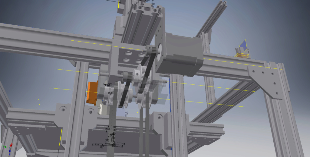
i tough about this i him gonna give a try to some belt , here my first idea using pulley, 20<60,20<60 , one set of pulley give me 480 e step i believe with 2 set should get a lot more resolution him just not sure of the exact number , probably 3x more if somebody can confirm this ?
here the first sketch i believe everything would be more compact as well these pulley are slightly thicker than the one him looking at . still need to think about a belt tensionner system probably adding some kind of arms either spring loaded or with a tightening bolt ,
2 belt linked to the shaft would insure the bed to move without much problem would be fixed somewhere on the platform
-
@Dad003 said in leadscrew vs ballscrew:
20<60,20<60 ,
i think it will give you 240 steps. (assuming 1.8 steppers)
you have twice a 3:1.
your actual belt to move the z is 60 tooth.
so 200/2/60* 1/16 microstepping 26.66
3:1 once is 80
3:1 twice is 240
the solution on the ender 3 is
16<80 which gives a 5:1 ratiothen use a 20 tooth to drive the belt.
200/2/20 * 1/16 microstepping = 80
5:1 with 80 is 400.
-
Just to be clear- you are saying that your 'out of straightness' leadscrew is putting enough lateral load on the build platform to give you Z-banding issues ? That does not make sense.
What may be the issue is the elastic buckling of that REALLY tall slender column. Peek into this rabbit hole - https://en.wikipedia.org/wiki/Euler's_critical_load
There are other theories, but this is the easiest to understand.Some quick and dirty estimating to put it in perspective- the normal range for compression members, we proportion them to a ratio of KL/r <200. For Tension members, we normally try to hole to KL/r<300. Since it a machine that we are try to get some manner of precision out of, I would not go over 80 in general.
A 700mm long TR8x8 leadscrew has an effective solid cross section of 6.5mm. This results in a KL/r of 461! Critical buckling load is about 17 pounds. This is kinda why TR8's dont scale well beyond i3 lengths. Look at the critical stress curve and about where i faked it in and plotted the resulting critical stress.

What might be an easier and faster mod to try and cure that is put the leadscrew in tension instead of compression. Use a stop collar and thrust bearing at the top and HANG the platform from above. Tension is self righting. You are mostly doing the same thing with a hanging belt drive, but adding ain a bunch of complexity with all the jackshafts.
-
@CaLviNx Yes, I am completely aware of that principle and my first thought was exactly what you are talking about, but in practice making a floating nut in a dual z-axis setup like mine (the z axis is holding the x-axis bar) and a height of 500mm that made more problems than solve. When the leadscrews are very long (like mine - almost 600mm) and you do not align them perfectly - the nut and/or screw tend to "dance" a bit which translates into visible z print artifacts. Using a springy motor coupler with a small ball bearing inside) helped a little bit with the constraint problems. When I was talking about aligning - I was thinking more about aligning the linear rails - since I have 4 of them for Z - 2 for each side od the Z axis, and aligning 4 linear rails to do a constrained up/down motion together is a pain. Also it's much more difficult when the lead on the leadscrew is 2mm instead of 8mm which is more common on printers since it's much more sensitive to misalignment.
-
@omni said in leadscrew vs ballscrew:
................ When the leadscrews are very long (like mine - almost 600mm) and you do not align them perfectly - the nut and/or screw tend to "dance" a bit which translates into visible z print artifacts.
If the linear rails are doing their job, and the screws are unconstrained, then any "dancing" of the nut or screw should not translate into any movement of the build platform. If it does, then there must be unacceptable play in the linear guides.
When I was talking about aligning - I was thinking more about aligning the linear rails - since I have 4 of them for Z - 2 for each side od the Z axis, and aligning 4 linear rails to do a constrained up/down motion together is a pain.
Which just means that you are using too many guides. You only need two, preferably located at opposite corners of the build platform. Located and aligned correctly, this is enough to prevent any movement in X, or Y and also any rotation.
Also it's much more difficult when the lead on the leadscrew is 2mm instead of 8mm which is more common on printers since it's much more sensitive to misalignment.
How so? How does the thread form affect the ability to align the screws? An 8mm lead, 4 start screw has the same 2mm pitch as a 2mm lead, single start screw.
For info, I use three unconstrained 8mm diameter 2mm lead screws, 900mm in length driven by a single motor and continuous belt, which raises and lowers a 400mm square build platform constrained by two linear guides arranged as detailed above. No Z artefacts, no need for any sort of software bed levelling or flatness compensation.
-
@deckingman said in leadscrew vs ballscrew:
Which just means that you are using too many guides. You only need two, preferably located at opposite corners of the build platform. Located and aligned correctly, this is enough to prevent any movement in X, or Y and also any rotation.
EXACTLY!