Duet3D Logo Duet3D
    • Tags
    • Documentation
    • Order
    • Register
    • Login

    ST3Di Modelsmart 280 - Duet Maestro repair/upgrade

    Scheduled Pinned Locked Moved
    My Duet controlled machine
    13
    139
    9.0k
    Loading More Posts
    • Oldest to Newest
    • Newest to Oldest
    • Most Votes
    Reply
    • Reply as topic
    Log in to reply
    This topic has been deleted. Only users with topic management privileges can see it.
    • Blacksheep99undefined
      Blacksheep99
      last edited by

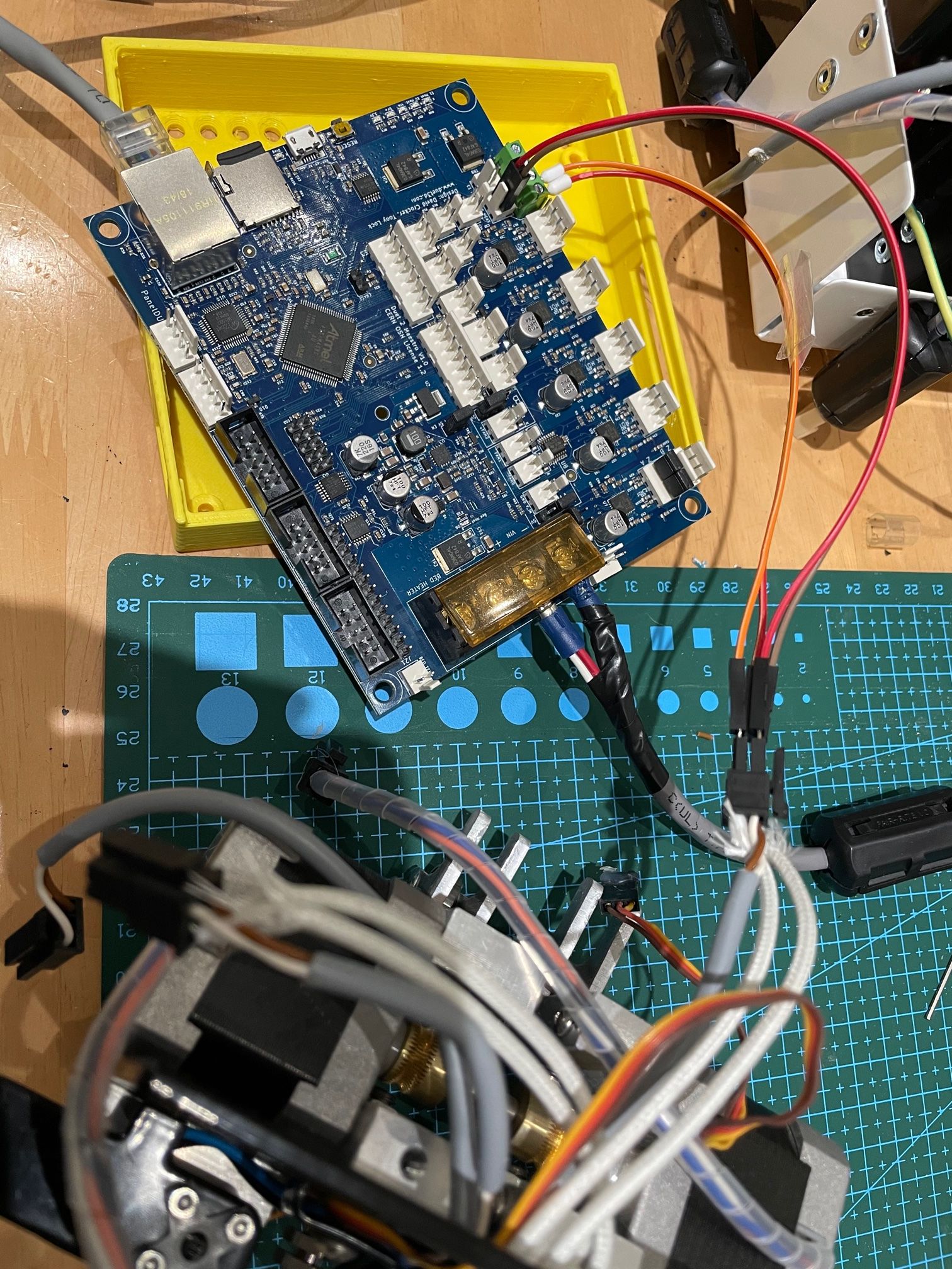
      Not sure these help?

      IMG_7277.jpg IMG_7285.jpg IMG_7284.jpg IMG_7283.jpg

      1 Reply Last reply Reply Quote 0
      • Blacksheep99undefined
        Blacksheep99
        last edited by

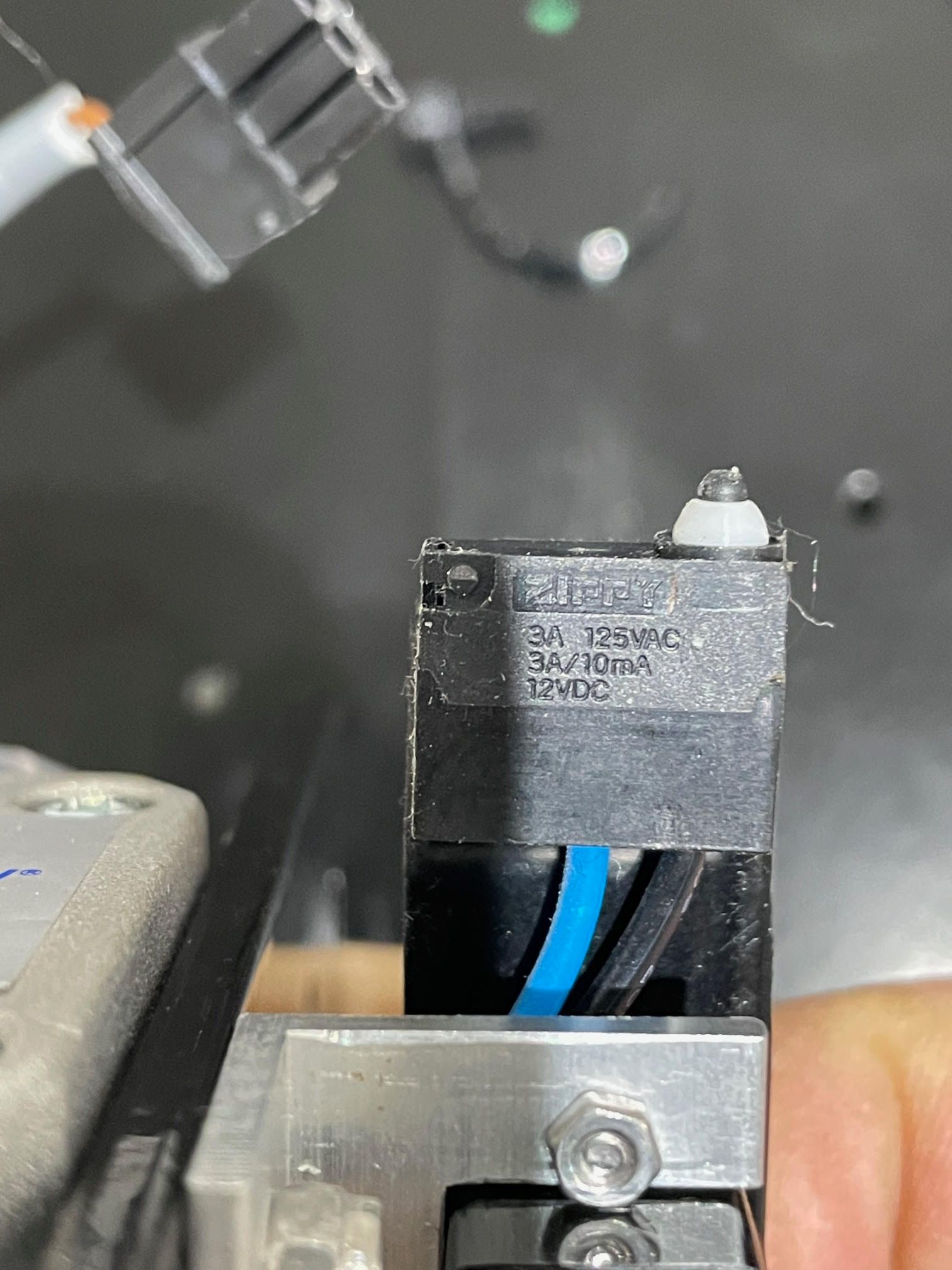
        The endstop/probe. 12v, is that an issue?

        Probe.jpg

        1 Reply Last reply Reply Quote 0
        • JamesMundefined
          JamesM
          last edited by JamesM

          It could just be a simple microswitch that is rated to handle 12 volts in which case it won't matter if you only use 3.3 volts. You'll need to just use an ohm meter on the wire ends to see if it that style switch. If it only has two wires I would suspect it's just a normal microswitch.

          Blacksheep99undefined 1 Reply Last reply Reply Quote 0
          • Blacksheep99undefined
            Blacksheep99 @JamesM
            last edited by

            @JamesM said in ST3Di Modelsmart 280 - Duet Maestro repair/upgrade:

            It could just be a simple microswitch that is rated to handle 12 volts in which case it won't matter if you only use 3.3 volts. You'll need to just use an ohm meter on the wire ends to see if it that style switch. If it only has two wires I would suspect it's just a normal microswitch.

            Thanks. I would think/hope you're right.

            1 Reply Last reply Reply Quote 0
            • A Former User?
              A Former User
              last edited by

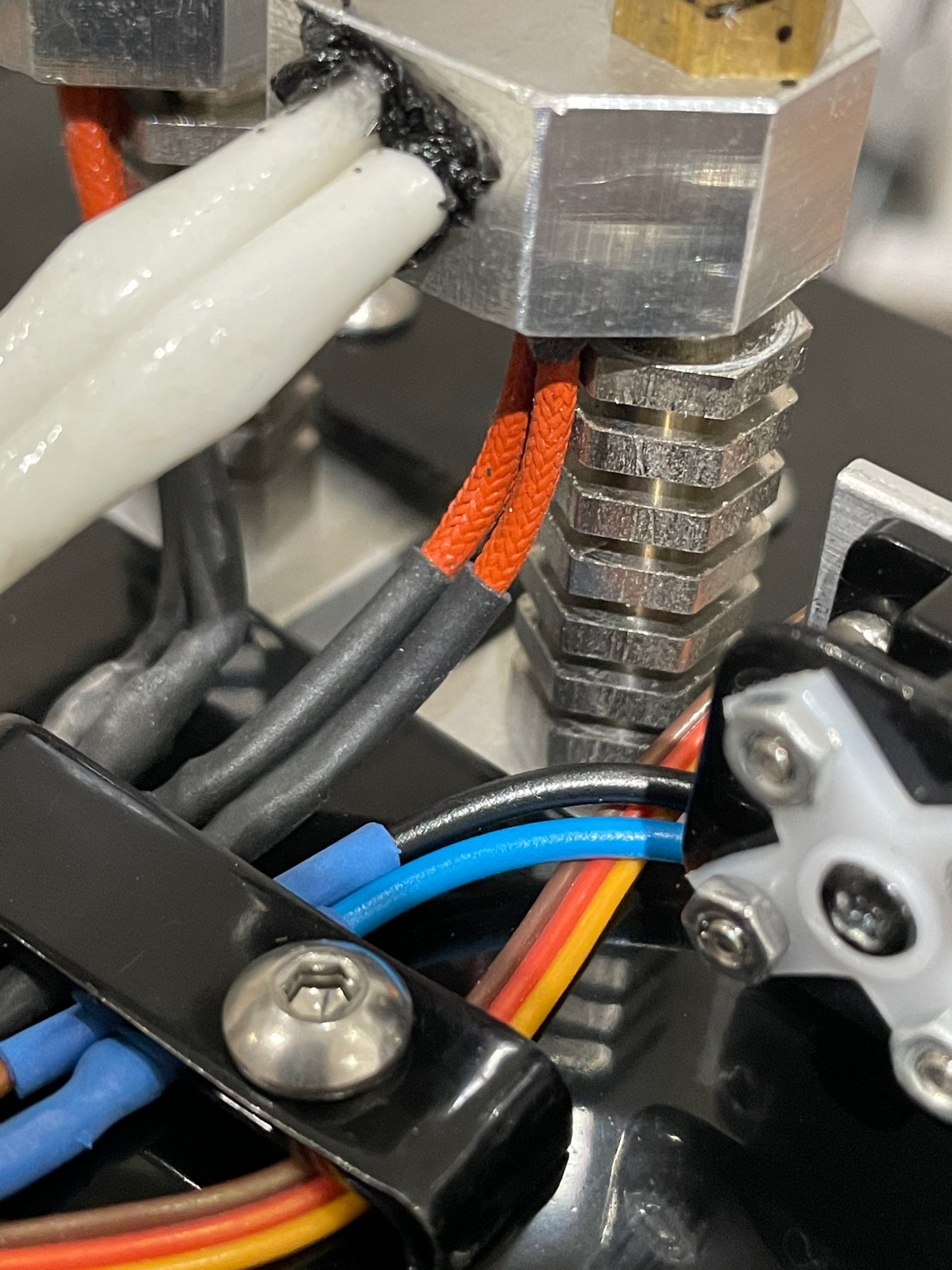
              Is the thermistor the white sleeved wirng or the red fiberglass insulated wiring? i'd guess the latter as the heater appears to be a cartridge poking out the other end.

              Blacksheep99undefined 1 Reply Last reply Reply Quote 0
              • Blacksheep99undefined
                Blacksheep99 @A Former User
                last edited by

                @bearer Sorry, it's the red wiring. The white ones are attached to the cartridge.

                1 Reply Last reply Reply Quote 0
                • A Former User?
                  A Former User
                  last edited by

                  Thats what I thought but the pictures seemed focused on the white wiring, I guess its hard to get a good angle on the thermistor then?

                  Blacksheep99undefined 1 Reply Last reply Reply Quote 0
                  • Blacksheep99undefined
                    Blacksheep99 @A Former User
                    last edited by

                    @bearer It's not too easy especially with the double print head. I'll try again now. I may take one apart if that would be helpful.

                    1 Reply Last reply Reply Quote 0
                    • A Former User?
                      A Former User
                      last edited by A Former User

                      If the wires just disappear into some black goo like the heater then i doubt we can identify them visually. But given the construction, a glass bead ntc is the most likely candidate if you want to replace it - but if the mounting is just some sort of adhesive or not idk.

                      1 Reply Last reply Reply Quote 0
                      • Blacksheep99undefined
                        Blacksheep99
                        last edited by

                        Pretty much

                        IMG_7288.jpg

                        1 Reply Last reply Reply Quote 0
                        • Vetiundefined
                          Veti
                          last edited by

                          well you can try your ir thermometer to see if the temperature is close

                          Blacksheep99undefined 1 Reply Last reply Reply Quote 0
                          • Blacksheep99undefined
                            Blacksheep99 @Veti
                            last edited by

                            @Veti On the heater block? As in wire up to the board and heat to 220? measure resistance ....

                            1 Reply Last reply Reply Quote 0
                            • Vetiundefined
                              Veti
                              last edited by

                              sorry i was under the impression you had an ir thermometer

                              Blacksheep99undefined 1 Reply Last reply Reply Quote 0
                              • Blacksheep99undefined
                                Blacksheep99 @Veti
                                last edited by

                                @Veti I have one of these

                                https://www.amazon.co.uk/gp/product/B01AT9TON0/ref=ppx_yo_dt_b_asin_title_o03_s00?ie=UTF8&psc=1

                                So heat in the oven and then if it measures 220 check resistance. Sorry if I'm been dense

                                1 Reply Last reply Reply Quote 0
                                • Vetiundefined
                                  Veti
                                  last edited by

                                  unless you have an all metal hotend, go for 200

                                  let it stay at that for a min or so and measure the temperature on the nozzle with the ir thermometer.

                                  1 Reply Last reply Reply Quote 0
                                  • A Former User?
                                    A Former User
                                    last edited by

                                    need to set the correct emissivity for the nozzle to get an reasonably accurate reading, but by the looks of it thats likely to be less accurate then just picking a beta value

                                    1 Reply Last reply Reply Quote 0
                                    • Blacksheep99undefined
                                      Blacksheep99
                                      last edited by

                                      Small update. I had a bit of time and I wanted to just test a few things. I decided to run the bed heater with the 'default' setting from the config tool. This is what I started with.

                                      code_text
                                      ; Heaters
                                      M308 S0 P"bedtemp" Y"thermistor" T100000 B4138  ; configure sensor 0 as thermistor on pin bedtemp
                                      M950 H0 C"bedheat" T0                           ; create bed heater output on bedheat and map it to sensor 0
                                      M307 H0 B0 S1.00                                ; disable bang-bang mode for the bed heater and set PWM limit
                                      M140 H0                                         ; map heated bed to heater 0
                                      M143 H0 S80                                     ; set temperature limit for heater 0 to 80C
                                      M308 S1 P"e0temp" Y"thermistor" T137000 B3478   ; configure sensor 1 as thermistor on pin e0temp
                                      M950 H1 C"e0heat" T1                            ; create nozzle heater output on e0heat and map it to sensor 1
                                      M307 H1 B0 S1.00                                ; disable bang-bang mode for heater  and set PWM limit
                                      M143 H1 S250                                    ; set temperature limit for heater 1 to 250C
                                      M308 S2 P"e1temp" Y"thermistor" T137000 B3478   ; configure sensor 2 as thermistor on pin e1temp
                                      M950 H2 C"e1heat" T2                            ; create nozzle heater output on e1heat and map it to sensor 2
                                      M307 H2 B0 S1.00                                ; disable bang-bang mode for heater  and set PWM limit
                                      M143 H2 S250  
                                      

                                      I ran the autotune for the bed. It gave me this override and I added the M501 to the end of my config

                                      ; config-override.g file generated in response to M500 at 2021-01-07 19:46
                                      ; This is a system-generated file - do not edit
                                      ; Heater model parameters
                                      M307 H0 R0.307 C525.917:525.917 D13.65 S1.00 V24.2 B0
                                      M307 H1 R2.429 C140.000:140.000 D5.50 S1.00 V0.0 B0
                                      M307 H2 R2.429 C140.000:140.000 D5.50 S1.00 V0.0 B0
                                      ; Workplace coordinates
                                      G10 L2 P1 X0.00 Y0.00 Z0.00
                                      G10 L2 P2 X0.00 Y0.00 Z0.00
                                      G10 L2 P3 X0.00 Y0.00 Z0.00
                                      G10 L2 P4 X0.00 Y0.00 Z0.00
                                      G10 L2 P5 X0.00 Y0.00 Z0.00
                                      G10 L2 P6 X0.00 Y0.00 Z0.00
                                      G10 L2 P7 X0.00 Y0.00 Z0.00
                                      G10 L2 P8 X0.00 Y0.00 Z0.00
                                      G10 L2 P9 X0.00 Y0.00 Z0.00
                                      M486 S-1
                                      

                                      During the bed test and after with my own tests using a IR thermometer gun I was getting within 1-2c of what the Duet was reporting so I was quite pleased to see that.

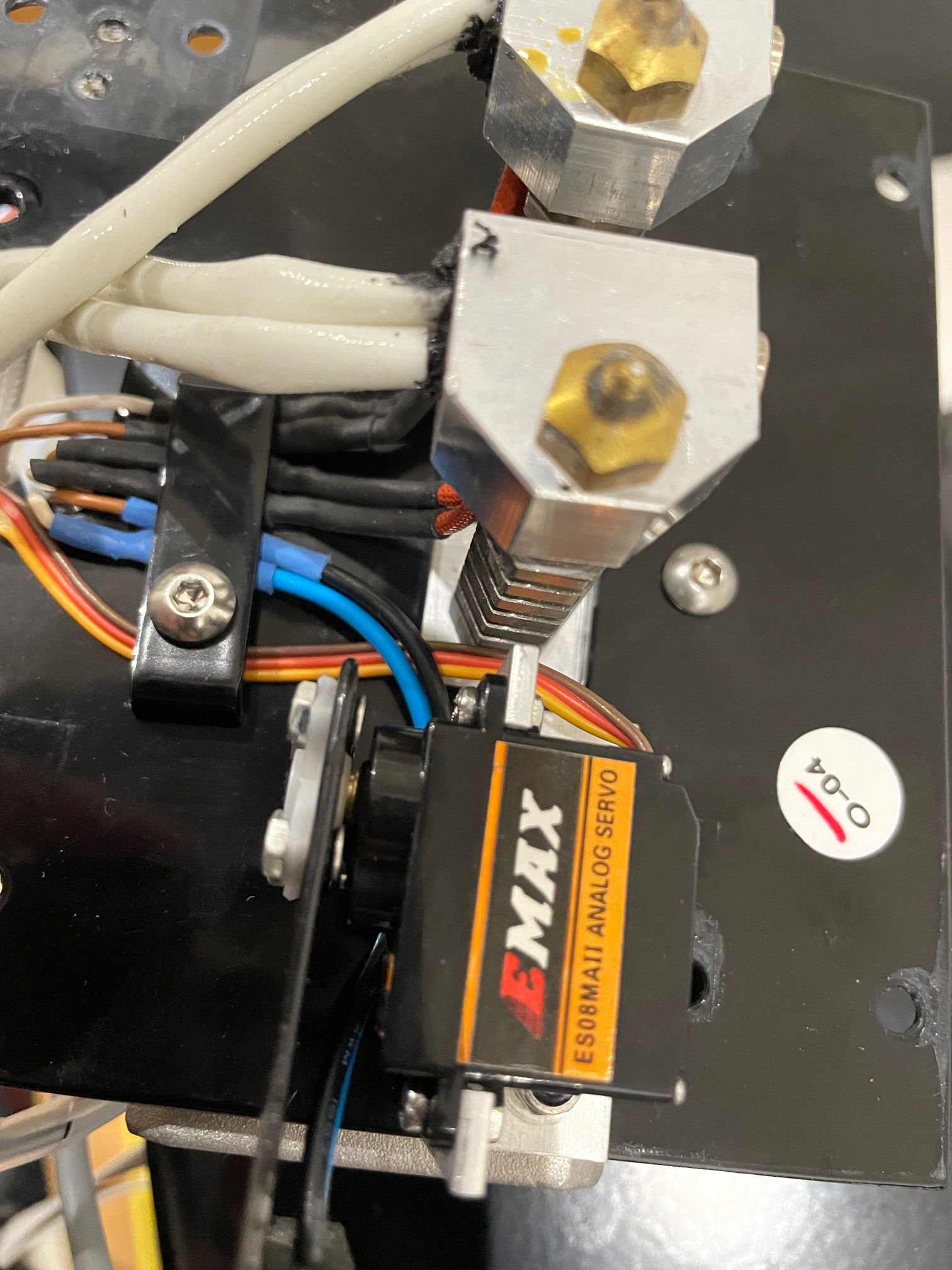
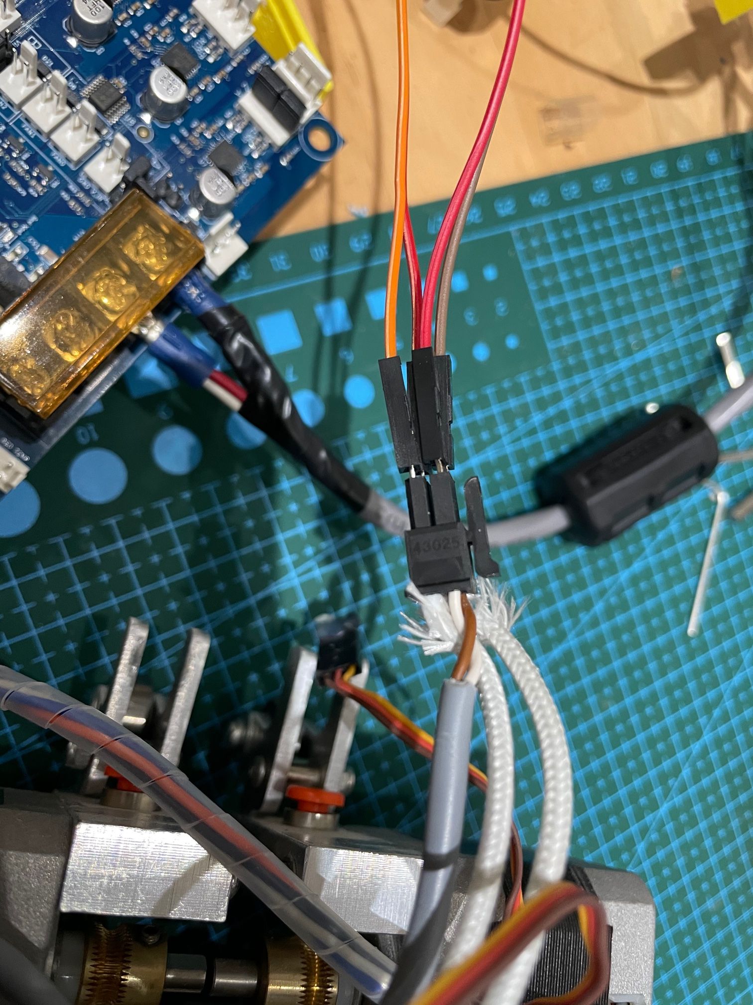
                                      I disconnected the bed and decided to see what the hotend was reporting. I've removed the hot end part of the carriage from the printer. I connected the heater and sensors to the E0 connections. For these purposes I have used Dupont wires, with bootlace and other supplied connector. Upon starting the board up I got this error.

                                      Error: Temperature reading fault on heater 0: sensor open circuit

                                      I've searched the error and it seems to tell me that there is no connection, there are reports of blown fuses but I don't believe that to be the issue. I have checked for resistance across the connections and it seems there's a connection.

                                      I've now left it as I don't want to do any damage. Any advice on what I need to check? Thanks.

                                      Pics

                                      IMG_7290.jpg IMG_7289.jpg

                                      1 Reply Last reply Reply Quote 0
                                      • Blacksheep99undefined
                                        Blacksheep99
                                        last edited by

                                        I've already realised my mistake! I connected to the wrong part of the board. I used E0 Heat when I should use E0 Temp!

                                        I'll leave the other post up as it's what I've been doing and also may serve as a lesson to others.... 😄

                                        1 Reply Last reply Reply Quote 0
                                        • Vetiundefined
                                          Veti
                                          last edited by

                                          @Blacksheep99 said in ST3Di Modelsmart 280 - Duet Maestro repair/upgrade:

                                          M308 S1 P"e0temp" Y"thermistor" T137000 B3478 ; configure sensor 1 as thermistor on pin e0temp

                                          i suggest you try the most common ones for the thermistors.
                                          thats B 3950
                                          epocs 100k
                                          semitec 104-gt2

                                          your settings seems very wrong.

                                          Blacksheep99undefined 1 Reply Last reply Reply Quote 0
                                          • Blacksheep99undefined
                                            Blacksheep99 @Veti
                                            last edited by

                                            @Veti Thanks. I'm thinking the easiest thing would be to buy two new thermistors for the hot end. Could you recommend ones available on amazon uk? I do have the offer of a k type thermocouple meter from a friend.

                                            I think the bed seems to behave and I doubt I'll need to go above 60c so I'm less concerned about that.

                                            Tonight I hope to look at the servo and probe. I intend to add a microswitch and use that as the X stop so the probe has a single purpose.

                                            1 Reply Last reply Reply Quote 0
                                            • First post
                                              Last post
                                            Unless otherwise noted, all forum content is licensed under CC-BY-SA