Duet Maestro Struggling to Produce Smooth Curves
-
Hi guys,
Over the past few days I have been doing a ton of testing trying to re-optimize my printer for optimal motion. This has involved using some formulaic custom gcode in SuperSlicer to vary one parameter at a time (jerk, accel, speed, etc).
What I am seeing after all of this is that the Maestro / RRF 3.2 is struggling to make smooth curves. The junctions between the straight line segments, regardless of how small, always seem to make visible artifacts.
Attached are my config.g and M122 report:
M122.txt
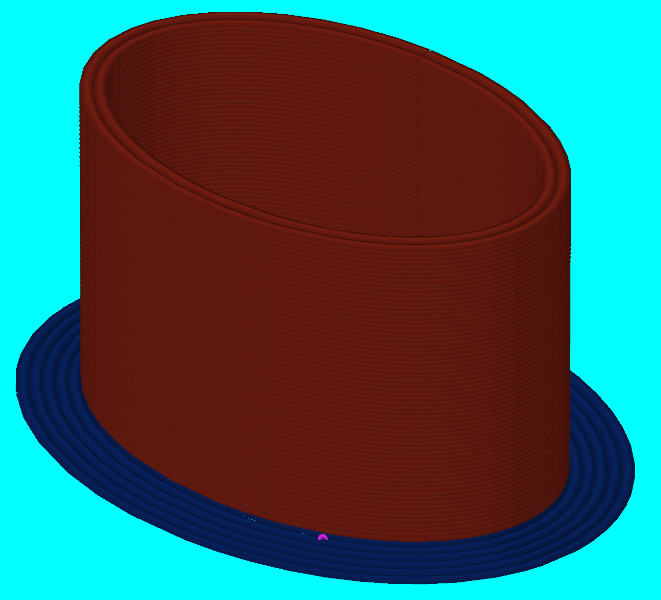
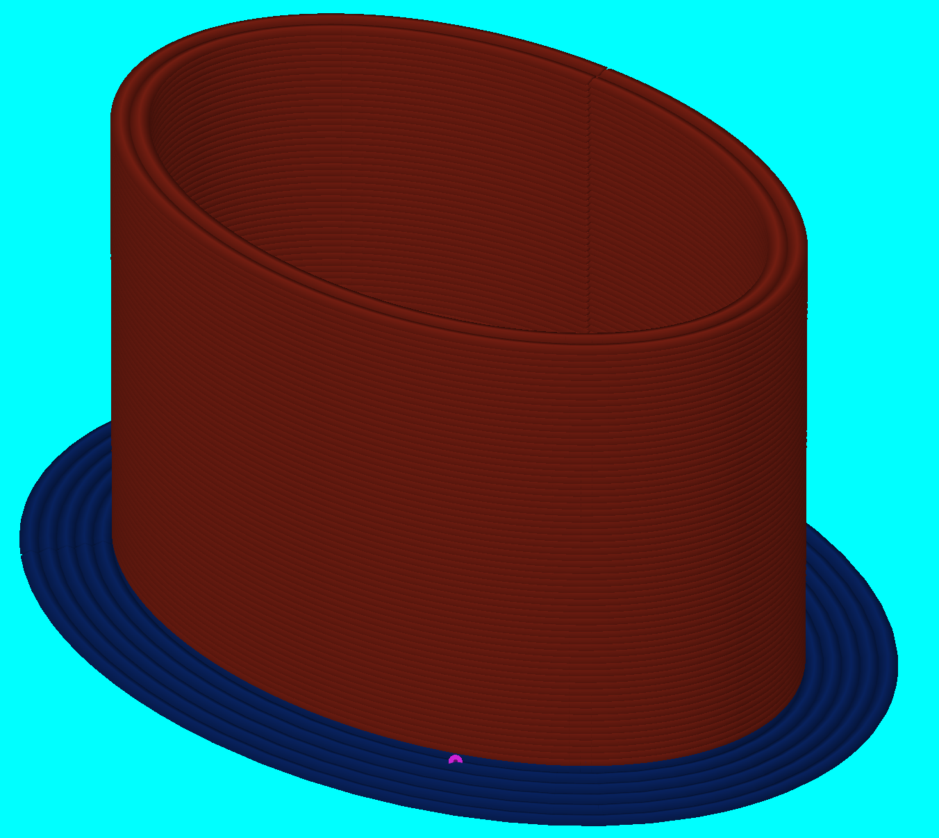
config.g.txtMany of these tests were using rescaled, inserted cylinders in SuperSlicer to avoid any potential STL issues.
Here is a 60mm/s oval, where XY jerk is varied by layer from 0 - 15 mm/s:
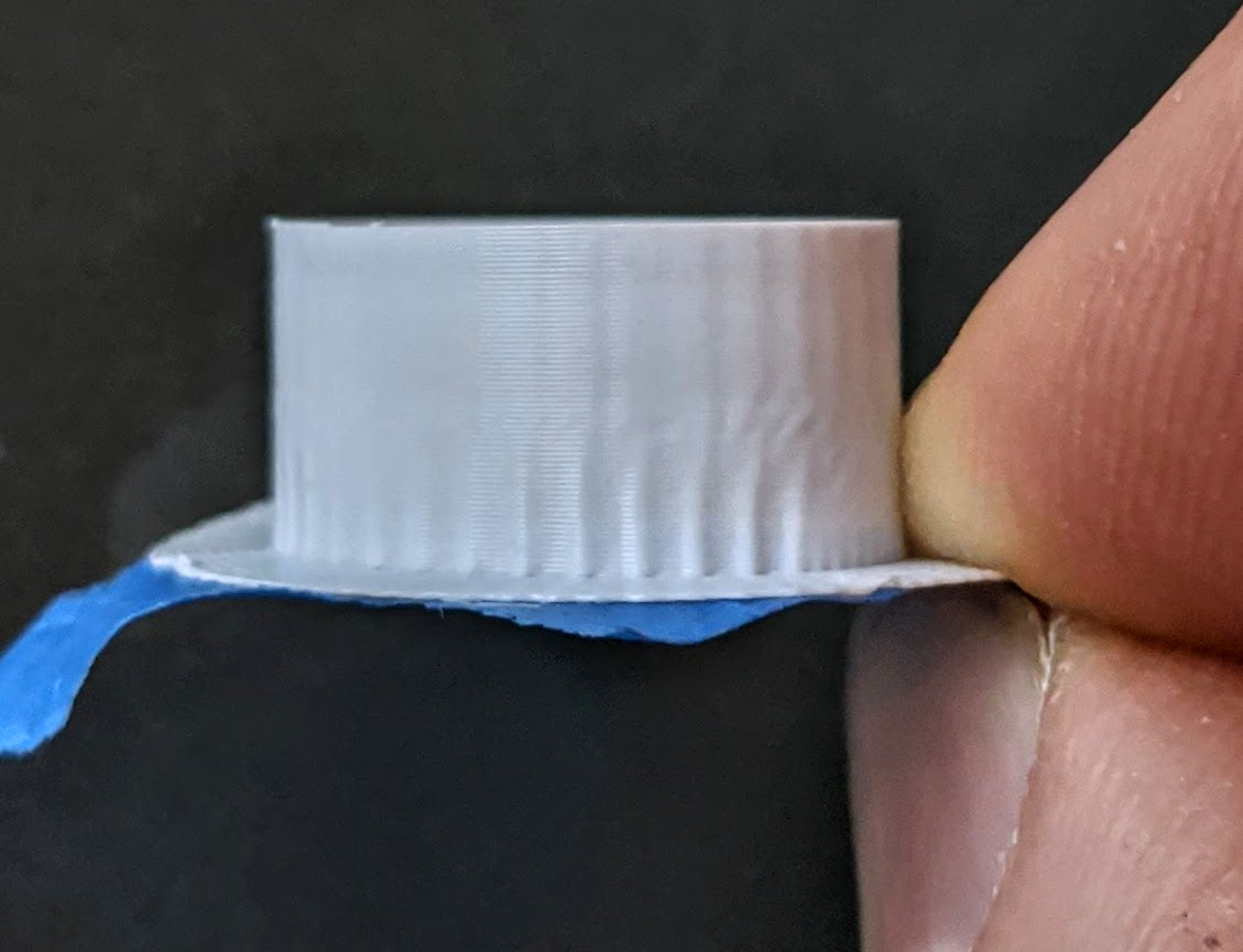
I settled on leaving XY jerk at 10 mm/s. Then I ran the same print varying XY accel from 500 - 3100:
Essentially no difference seen. But the segment junctions are still visible throughout.
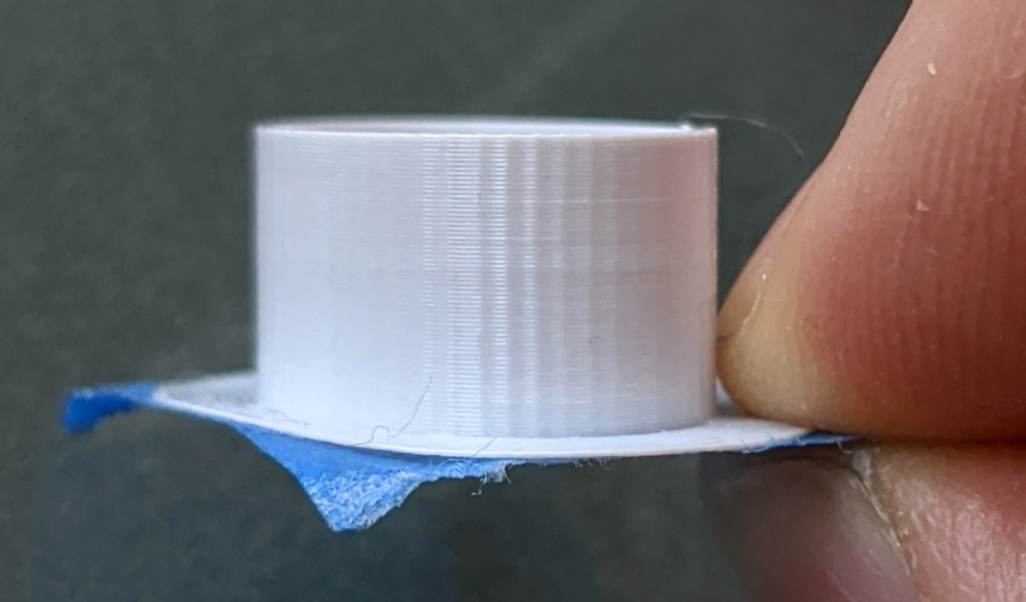
I then played with the "minimum extrusion length" advance machine setting in SuperSlicer (which I think is more of a max deviation because segment lengths are much larger than this value). The default setting is 0.035mm. Here is a video of the two prints comparing 0.035mm to 0.003mm:
https://photos.app.goo.gl/wSFTrQR4MhQ6ZScY7
While there are still visible artifacts, they are much less noticeable. The Maestro does well to eat up this extra dense gcode without underrunning the buffer. But I can't help but to wish that it could run smoother motion with less dense code. Here is a comparison of the facet size between those two prints. They are pretty small at 0.035mm and you essentially cannot even see them at the 0.003mm setting:
Am I missing something here? I really hope that I can improve from here with the current software and hardware. Otherwise, it seems like the improvement would need to come from a future firmware revision that does more intelligent path planning / look ahead, using maximum allowable path deviation to smooth junctions, instead of relying on "jerk" to stumble across every junction like this.
-
The print head motion appears smooth, but you can feel some "roughness" through the frame:
-
This is pretty interesting. I installed arcwelder for Cura and used it to take a hollow cylinder down from a 250kB file to 80kB. Even with arcs, I see pulsed artifacts:
Here is the gcode for a single perimeter:
G0 F7650 X66.46 Y133.941
;TYPE:WALL-OUTER
G3 X59.665 Y131.199 I-0.004 J-9.780 E18.81959 F2700
G3 X56.678 Y124.500 I6.796 J-7.046 E18.89384
G3 X59.175 Y117.612 I9.776 J-0.353 E18.96800
G3 X65.774 Y114.385 I7.287 J6.541 E19.04236
G3 X72.742 Y116.642 I0.691 J9.751 E19.11650
G3 X76.195 Y123.114 I-6.281 J7.508 E19.19075
G3 X74.174 Y130.180 I-9.725 J1.040 E19.26515
G3 X67.884 Y133.837 I-7.718 J-6.036 E19.33876
G0 F2430 X67.829 Y133.845
I tried running this code with interpolation off, at x32 microstepping and at x8. But the pattern continues...
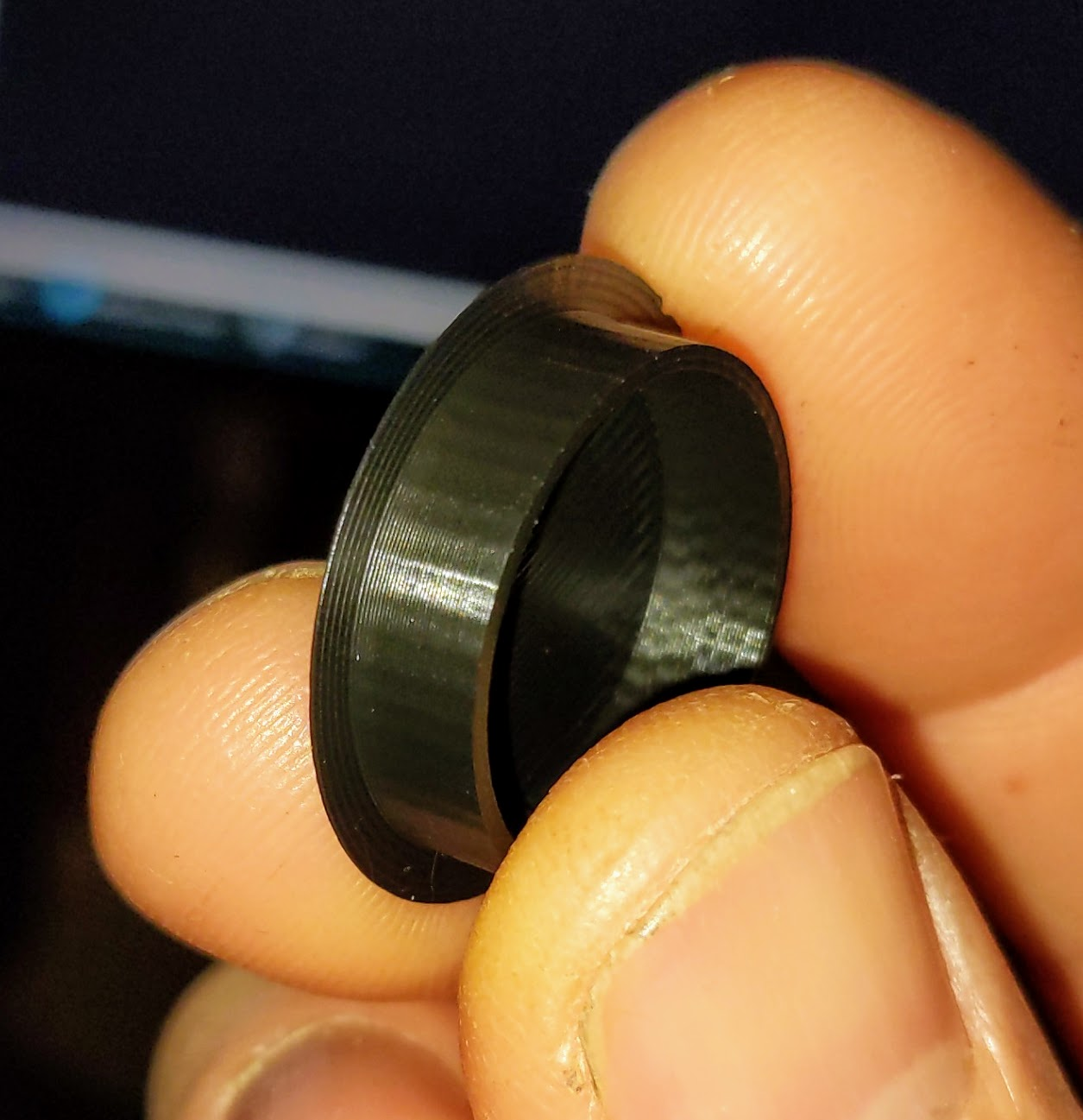
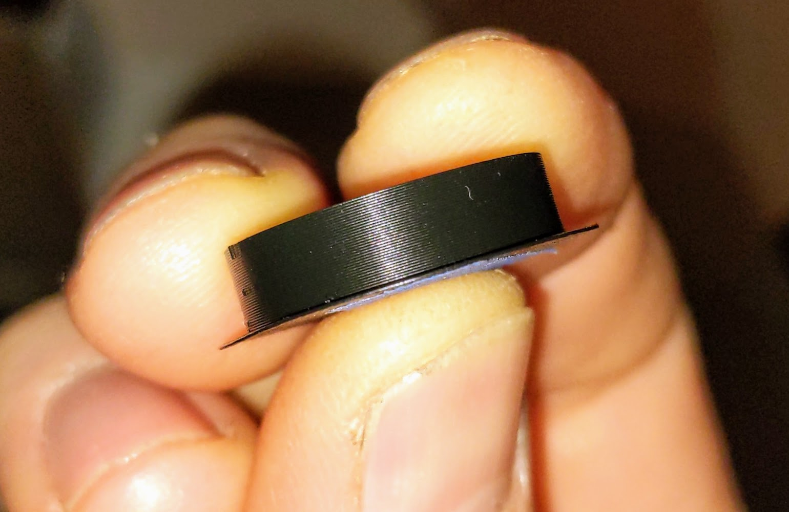
Is there anything about my stepper motor spec that could cause this?
-
Here is point to point code at 20 mm/s:
-
Jerk settings?
-
@CCS86 Do you have gt2 belt running over smooth idler bearings? That can cause the machine/frame to vibrate. (roughness as you called it)
-
@CCS86 That "point to point code at 20mm" looks much better in the photo does it to you? If it does can you explain what is different between it and the other tests you have been running? Is it simply the speed that is different?
-
This post is deleted! -
@Blacksheep99 said in Duet Maestro Struggling to Produce Smooth Curves:
Jerk settings?
In the first post.
@o_lampe said in Duet Maestro Struggling to Produce Smooth Curves:
@CCS86 Do you have gt2 belt running over smooth idler bearings? That can cause the machine/frame to vibrate. (roughness as you called it)
@gloomyandy said in Duet Maestro Struggling to Produce Smooth Curves:
@CCS86 That "point to point code at 20mm" looks much better in the photo does it to you? If it does can you explain what is different between it and the other tests you have been running? Is it simply the speed that is different?
It is an Ultimaker motion system, converted to GT2, so no smooth pulleys. The pulleys are high quality (low runout).
I included the 20mm/s print because the surface finish looks nearly perfect to me. This was to show that mechanically I can get very clean motion in the printer's current state. I would just like improve things around the 60mm/s speed, because even if I slow down the outer perimeters, if the inner walls have these artifacts, they will show through to some degree.
-
I'm no expert on this but it makes me think there is increased motor cogging torque at the higher speeds?
-
@Phaedrux
I'm no expert in steppers, but motors in general have the same max. torque until 50% of their max. RPM. Then the torque fades out. (This rule is for current limited drivers)
The cogging torque instead is a mechanical thing, not based on electric current, but magnetic attraction. Why would that grow at higher speeds, where instead inertia takes over?@CCS86 My last straw are the linear bearings. Do you hear or feel any flat spot in the bearings or resonance at higher speeds? I watched the short video and couldn't hear anything except the fans.
I can highly recommend using IGUS Drylin linear bearings against the ball racing bearings. -
I notice you have the following for your steps/mm:
M92 X159.93 Y159.75 Z400.00 E510
that seems a little odd what are the actual mechanics of the X and Y axis?What sort of results do you get with just a single wall is it the same? If you print a test and vary the motor current from lower to higher do you see any difference?
-
I'm also using the "rounding" feature of Supermerill's SuperSlicer.
My jerk settings are: 240 mm/min and
acceleration for external perimeter: 800mm/s
Print speed for external perimeter: 25 mm/sThe results are very clean with almost no ringing or artefacts, printing a round object made "rounder" with SuperSlicer.
Even if the preview in the Slicer looks round I don't think this translates 1:1 into gcode or the printer and if you print too fast you can still see artefacts.
Maybe it is possible in the future to have some sort of "logic" so the firmware detects a round objects and does not strictly follow the gcode but plans it own round path.
-
@Argo said in Duet Maestro Struggling to Produce Smooth Curves:
I'm also using the "rounding" feature of Supermerill's SuperSlicer.
My jerk settings are: 240 mm/min and
acceleration for external perimeter: 800mm/s
Print speed for external perimeter: 25 mm/sThe results are very clean with almost no ringing or artefacts, printing a round object made "rounder" with SuperSlicer.
Even if the preview in the Slicer looks round I don't think this translates 1:1 into gcode or the printer and if you print too fast you can still see artefacts.
Maybe it is possible in the future to have some sort of "logic" so the firmware detects a round objects and does not strictly follow the gcode but plans it own round path.
Which setting are you talking about? There isn't one called "rounding". There is "model rounding precision". Or maybe you are talking about "curve smoothing"?
Either way, my results show that increasing the segment count in a curve (reducing the angular change at a segment junction) improves quality. It just seems like something about the RRF motion control is a bit too sensitive to these junctions. But printing G2/G3 arcs actually makes quality a bit worse.
Getting high quality at 25 mm/s is no problem. I'd like to expand that up to ~60mm/s for nice smooth curves.
-
@gloomyandy said in Duet Maestro Struggling to Produce Smooth Curves:
I notice you have the following for your steps/mm:
M92 X159.93 Y159.75 Z400.00 E510
that seems a little odd what are the actual mechanics of the X and Y axis?What sort of results do you get with just a single wall is it the same? If you print a test and vary the motor current from lower to higher do you see any difference?
Are you talking about the difference in steps for X and Y? It's an Ultimaker motion system, so rotation is converted to linear motion of the print head by GT2 pulleys. They have tolerances like everything else, so small changes in the pulley diameter can cause slight differences like this. It's only 0.1% different, but it makes for more accurate prints.
1 wall prints are the same. I started doing them in 2 and 3 wall to make sure it wasn't the actual print oscillating.
I like the idea of varying motor current. I'll probably give that a try too.
-
Yep curve smoothing. Wasn't on my computer when posting so I couldn't look up the exact name of the feature.
Can you print nice round objects with Marlin 2? The results at 60 mm/s look pretty much the same with my SKR 1.4 and Marlin 2. I don't think it's a problem of RRF.
-
@o_lampe said in Duet Maestro Struggling to Produce Smooth Curves:
@Phaedrux
I'm no expert in steppers, but motors in general have the same max. torque until 50% of their max. RPM. Then the torque fades out. (This rule is for current limited drivers)
The cogging torque instead is a mechanical thing, not based on electric current, but magnetic attraction. Why would that grow at higher speeds, where instead inertia takes over?@CCS86 My last straw are the linear bearings. Do you hear or feel any flat spot in the bearings or resonance at higher speeds? I watched the short video and couldn't hear anything except the fans.
I can highly recommend using IGUS Drylin linear bearings against the ball racing bearings.The linear bearings seem to be in great shape. I have checked them individually. I think that if I had issues with bearings: 1) I would see them even during straight wall sections (I don't), and 2) the artifacts wouldn't be so perfectly spaced
-
@Argo said in Duet Maestro Struggling to Produce Smooth Curves:
Yep curve smoothing. Wasn't on my computer when posting so I couldn't look up the exact name of the feature.
Can you print nice round objects with Marlin 2? The results at 60 mm/s look pretty much the same with my SKR 1.4 and Marlin 2. I don't think it's a problem of RRF.
I haven't printed with Marlin 2 in a long time, so I couldn't say.
Curve smoothing seems to be mainly for improving low resolution STLs. The vast majority of my prints are from my own designs, so I can output them at whatever resolution I need.
-
I really want to make sure my stepper motors themselves and configuration aren't holding me back.
There are 2-phase motors, yes? Does that mean that they are rated for 4 amps in the same context as this recommendation, or it is just an accident that it looks like "amps per phase"?
Duet 2 Maestro (recommended maximum motor current 1.4A RMS with good fan cooling) => Stepper motor rated current <= 1.7A. Hower, if you use motors with lower rated current (e.g. 1.0 to 1.2A) and 24V power, then the drivers will run cooler.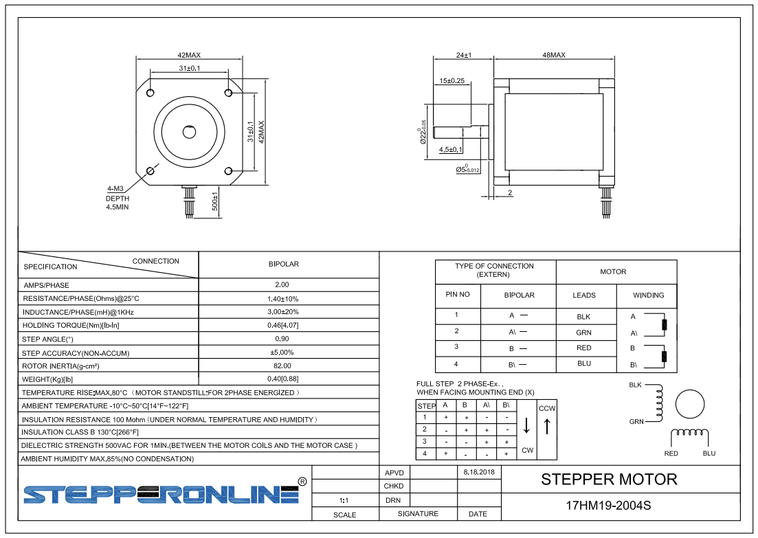
I am running at 24v, and have them in Spreadcycle mode because the Stealthchop switch is pretty ugly.
-
The motors have a higher rated current than we recommend for the Maestro, however I doubt that's part of the problem. If it were, then you would see ripples on flat surfaces as well as on curves.
If the faceting occurs only on curves, then it's a feature of the GCode file and/or the slicer, but most likely the GCode file. It might be exacerbated by the extrusion mechanics if the XY jerk settings are too low to allow the facets to be printed at constant speed, and there isn't sufficient pressure advance to compensate that. That effect is clearly visible in your first image. In that image, it appears that about half way up the print, you have increased the allowed XY jerk sufficiently to allow the print to proceed at constant speed. Above that, the firmware is just printing the facets that the GCode file told it to.
If you want finer facets, then I think you will need to go back to the original model and export it to STL with finer facets. Alternatively, you may be able to use a GCode post-processor such as Arc Welder to turn the facets into G2/G3 curves.
Duet WiFi hardware designer and firmware engineer
Please do not ask me for Duet support via PM or email, use the forum
http://www.escher3d.com, https://miscsolutions.wordpress.com