always on fan not working ( 0.2V )
-
Hello everyone,
Right now I have a 24V 30mm extruder fan connected to Fan 1 (turns on when temp exceeds around 40 degrees C )
Now I have bought a 5V 40mm Noctua fan to replace the 30mm fan.
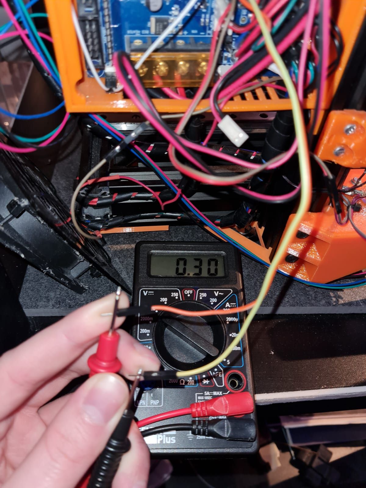
I wanted to connect the fan to the always on fan connector set to 5V but the fan didnt do anything. when using a multimeter I read 0.2V on the always on fan pins. when I switch the jumper to VIN (24V) I still read 0.2V on the pins.
Is there something wrong with the board, or do I need to turn some settings on to get the fan to work?
It would be strange if there is something broken because I have never used the always on fan pins before.
Thanks in advance,
Michel -
What kind of board do you have?
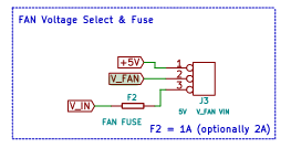
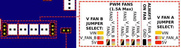
- Is your 2-pin fan-voltage-selction jumper working?
- Do you read 5 Volts on the 5V pin in the three-pin fan voltage selection jumper?
- Can you check the continuity between the center pin of the fan-voltage-selection and the V-FAN pin on the always-on 2-pin fan connector?
-
What kind of board do you have?
Oh yeah forgot to mention... It's a Duet 2 maestro.
Is your 2-pin fan-voltage-selction jumper working?
I guess Its working, he looks fine and if tested another jumped with the same results.
Do you read 5 Volts on the 5V pin in the three-pin fan voltage selection jumper?
When testing between the ground (2-pin) and the 5V (3-pin) I got 0.15 volt.
When testing between the ground (2-pin) and the VIN (3-pin) I got 0.22 volt.Can you check the continuity between the center pin of the fan-voltage-selection and the V-FAN pin on the always-on 2-pin fan connector?
Yes I do have continuity between the center pin and the V-FAN pin on the 2-pin
-
If you don't have +5 on the fan voltage selector, maybe you have a bad solder joint?
There's nothine else between that pin and +5 and I ASSUME you have +5. -
Is there another way to test if my +5V is working?
-
@micheldb14 I don't think ANYTHING would work if you don't have +5
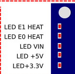
- There's a RED LED that lights up saying if +5 is working.
(I think they are Blue = Vin, Red = +5 and green=+3.3)
- There's a RED LED that lights up saying if +5 is working.
-
yeah all the leds (VIN, 5V and 3,3V) are on
-
@micheldb14 I would say check the solder joints to see if they look poor.
I can't think of a reason to have the 5 Volt LED on and not have 5 Volts at the fan voltage connector.
Maybe @dc42 has an idea about +5 voltage routing.
-
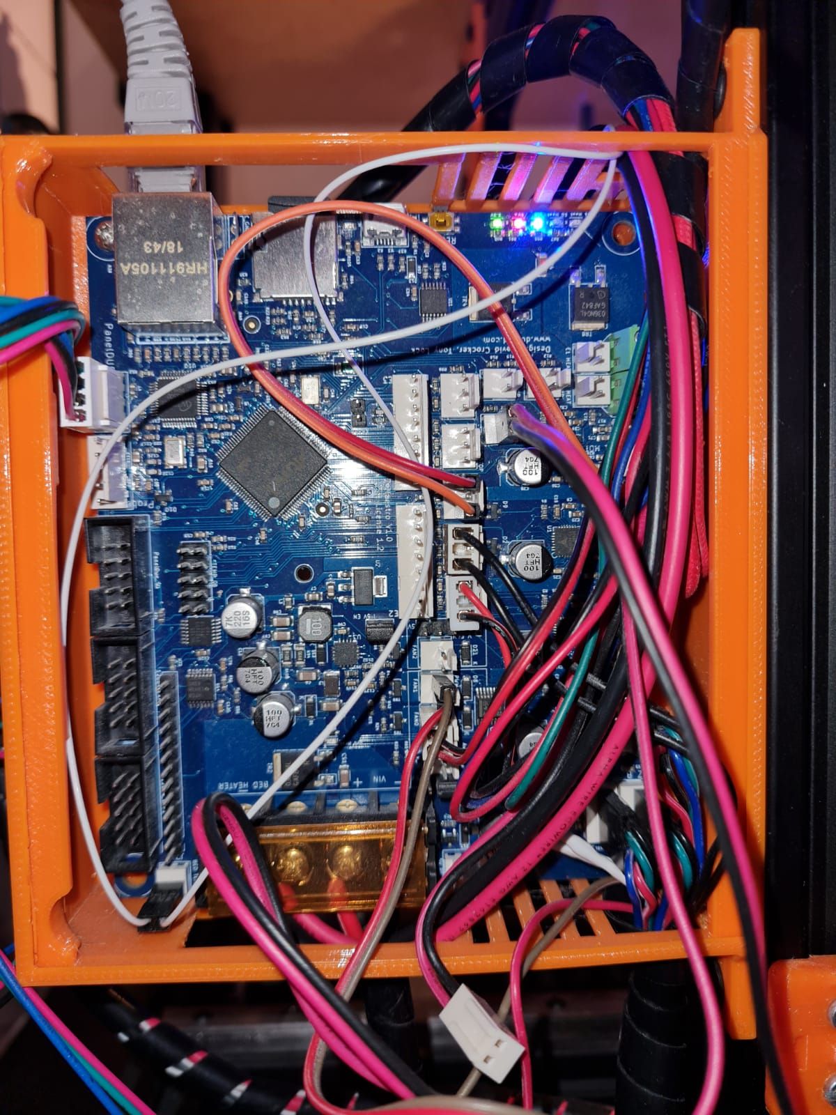
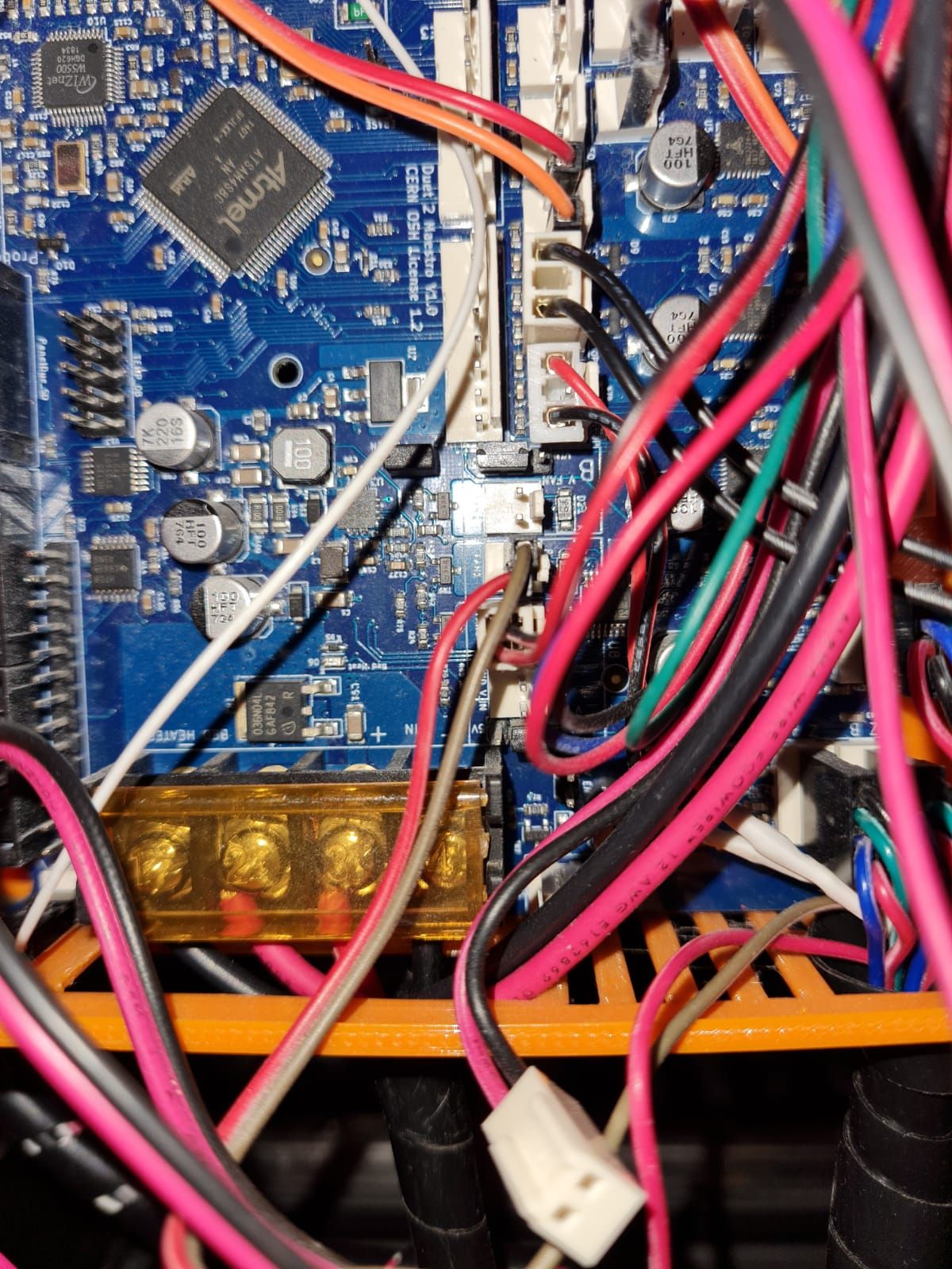
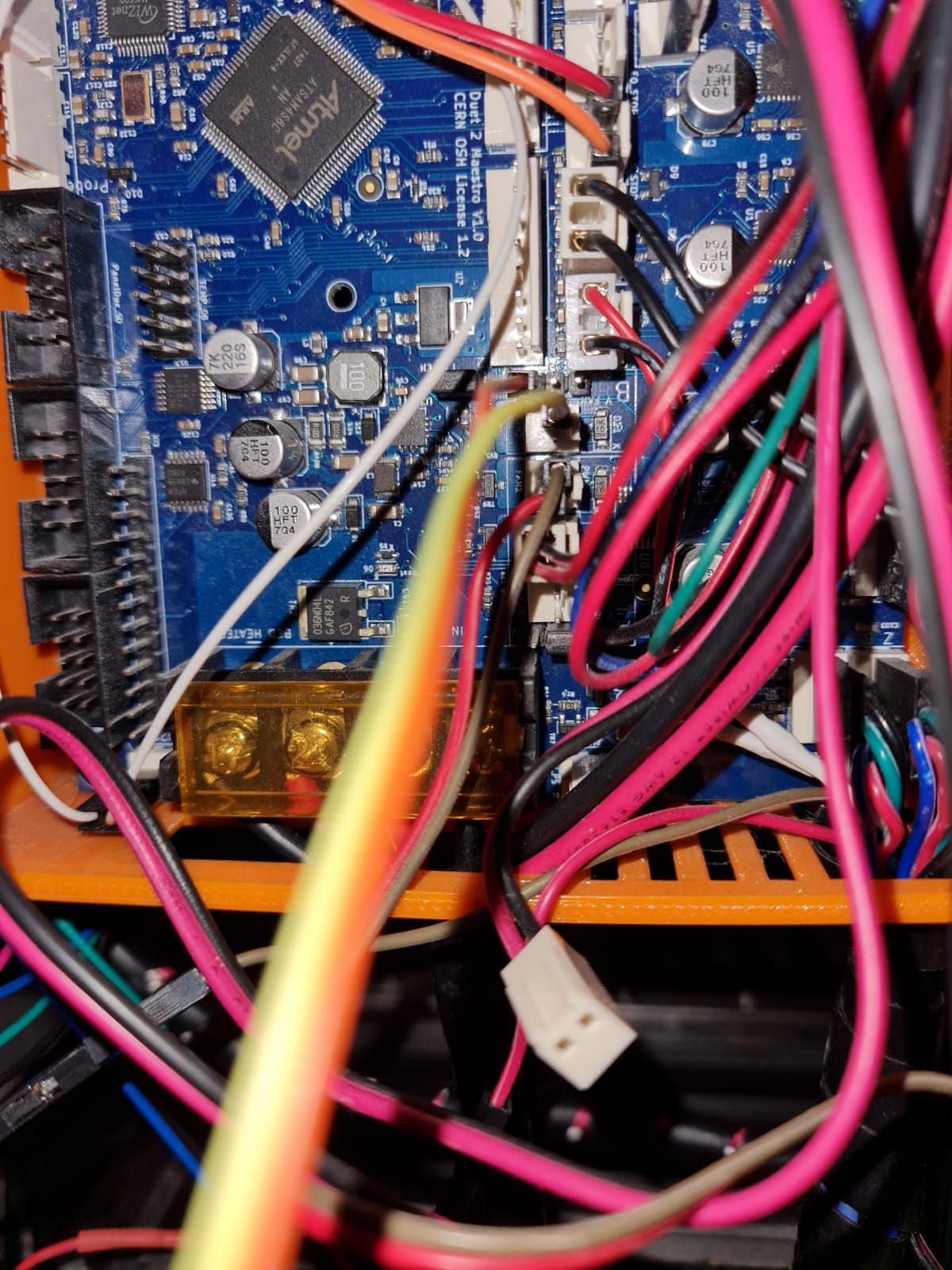
Can you post a photo of the board and close up of the fan headers?
You're saying the 5v V_fan pin on the voltage selector block isn't providing 5v at all?
-
-
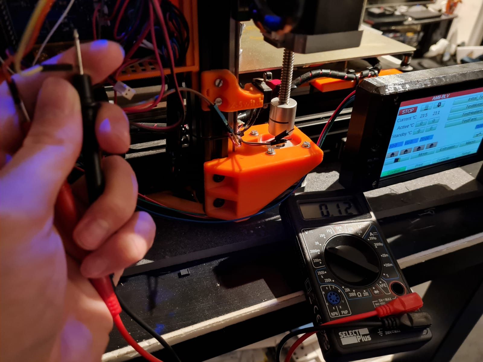
@micheldb14 And that's measuring fan2 header, correct?
What do you get on the 5v pin of the jumper block itself?
-
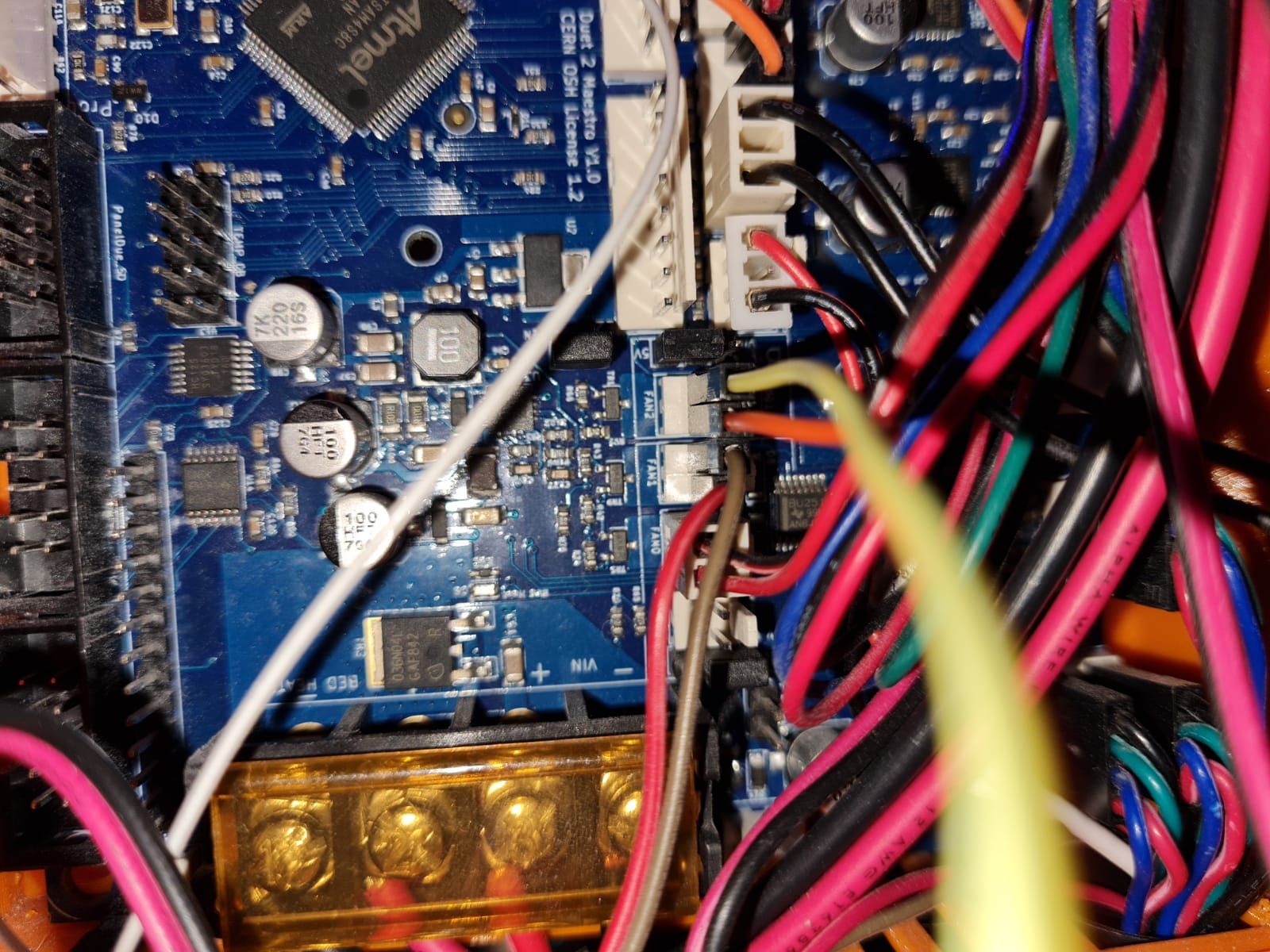
Yes, the 2 wires are connected to the FAN2 pins as shown in the 3rd picture
-
Bed-slinger - Mini5+ WiFi/1LC | RRP Fisher v1 - D2 WiFi | Polargraph - D2 WiFi | TronXY X5S - 6HC/Roto | CNC router - 6HC | Tractus3D T1250 - D2 Eth
-
-
oh man..... thanks! I thought FAN2 was the always on fan because it a had a seperate 5V/VIN switch...now it all makes sense...
-
@micheldb14 You are still measuring onto a PWM pin (yellow wire), ie it's turned off unless you've defined a fan on it in config.g and turned it on. MOSFETs that controls PWM are always on the negative (ground) side, because they need to be placed after the 'load'.
Edit: Glad you got it figured out!
Ian
Bed-slinger - Mini5+ WiFi/1LC | RRP Fisher v1 - D2 WiFi | Polargraph - D2 WiFi | TronXY X5S - 6HC/Roto | CNC router - 6HC | Tractus3D T1250 - D2 Eth
-
So just to clear things up.
There is one jumper just to switch between 5V and VIN on FAN2
And the other Jumper is to switch 5V and VIN for FAN1, FAN0 and ALWAYS-ON FAN?If this is the case, is there a way to set FAN2 as extruder fan so it will turn on when the hotend gets hot? (what now is the case with FAN1)
-
@micheldb14 said in always on fan not working ( 0.2V ):
So just to clear things up.
There is one jumper just to switch between 5V and VIN on FAN2
And the other Jumper is to switch 5V and VIN for FAN1, FAN0 and ALWAYS-ON FAN?Yes, that is correct.
If this is the case, is there a way to set FAN2 as extruder fan so it will turn on when the hotend gets hot? (what now is the case with FAN1)
Post your config.g and response to M115, so we know how it’s currently set and what firmware you are on.
Ian
Bed-slinger - Mini5+ WiFi/1LC | RRP Fisher v1 - D2 WiFi | Polargraph - D2 WiFi | TronXY X5S - 6HC/Roto | CNC router - 6HC | Tractus3D T1250 - D2 Eth
-
@droftarts
M115
FIRMWARE_NAME: RepRapFirmware for Duet 2 Maestro FIRMWARE_VERSION: 3.1.1 ELECTRONICS: Duet Maestro 1.0 FIRMWARE_DATE: 2020-05-19b2config.g:
; Configuration file for Duet Maestro (firmware version 3)
; executed by the firmware on start-up
;
; generated by RepRapFirmware Configuration Tool v3.1.4 on Tue Jul 14 2020 22:20:39 GMT+0200 (Midden-Europese zomertijd); General preferences
G90 ; send absolute coordinates...
M83 ; ...but relative extruder moves
M550 P"AM8-BLV" ; set printer name
M918 P1 E4 F2000000 ; configure direct-connect display; Network
M552 P0.0.0.0 S1 ; enable network and acquire dynamic address via DHCP
M586 P0 S1 ; enable HTTP
M586 P1 S0 ; disable FTP
M586 P2 S0 ; disable Telnet; Drives
M569 P0 S1 D2 ; physical drive 0 goes forwards in spreadcycle
M569 P1 S1 D2 ; physical drive 1 goes forwards in Stealthchop2 till about 150 mm/sec
M569 P2 S0 D2 ; physical drive 2 goes forwards in Stealthchop2
M569 P3 S1 D2 ; physical drive 3 goes forwards in spreadcycle
M584 X0 Y1 Z2 E3 ; set drive mapping
M350 X16 Y16 Z16 E16 I1 ; configure microstepping with interpolation
M92 X200.00 Y200.00 Z1600.00 E411.00 ; set steps per mm
M566 X600.00 Y600.00 Z12.00 E120.00 ; set maximum instantaneous speed changes (mm/min)
M203 X18000.00 Y18000.00 Z180.00 E1200.00 ; set maximum speeds (mm/min)
M201 X1000.00 Y800.00 Z20.00 E250.00 ; set accelerations (mm/s^2)
M906 X1100 Y1100 Z1100 E1000 I30 ; set motor currents (mA) and motor idle factor in per cent
M84 S30 ; Set idle timeout; Axis Limits
M208 X-25 Y-25 Z0 S1 ; set axis minima
M208 X215 Y215 Z250 S0 ; set axis maxima; Endstops
M574 X1 S1 P"!^xstop" ; configure active-high endstop for low end on X via pin xstop
M574 Y1 S1 P"!^ystop" ; configure active-high endstop for low end on Y via pin ystop
M574 Z1 S1 P"!^zstop" ; configure active-high endstop for low end on Z via pin zstop; Z-Probe
M558 P0 H5 F120 T6000 ; disable Z probe but set dive height, probe speed and travel speed
M557 X10:200 Y10:195 S20 ; define mesh grid; Heaters
M308 S0 P"bedtemp" Y"thermistor" T100000 B4725 C7.06e-8 ; configure sensor 0 as thermistor on pin bedtemp
M950 H0 C"bedheat" T0 ; create bed heater output on bedheat and map it to sensor 0
M307 H0 B1 S1.00 ; enable bang-bang mode for the bed heater and set PWM limit
M140 H0 ; map heated bed to heater 0
M143 H0 S120 ; set temperature limit for heater 0 to 120C
M308 S1 P"e0temp" Y"thermistor" T100000 B4725 C7.06e-8 ; configure sensor 1 as thermistor on pin e0temp
M950 H1 C"e0heat" T1 ; create nozzle heater output on e0heat and map it to sensor 1
M307 H1 B0 S1.00 ; disable bang-bang mode for heater and set PWM limit; Fans
M950 F0 C"fan0" Q500 ; create fan 0 on pin fan0 and set its frequency
M106 P0 S0 H-1 ; set fan 0 value. Thermostatic control is turned off
M950 F1 C"fan1" Q500 ; create fan 1 on pin fan1 and set its frequency
M106 P1 S1 H1 T45 ; set fan 1 value. Thermostatic control is turned on; Tools
M563 P0 D0 H1 F0 ; define tool 0
G10 P0 X0 Y0 Z0 ; set tool 0 axis offsets
G10 P0 R0 S0 ; set initial tool 0 active and standby temperatures to 0C; Custom settings are not defined
; Miscellaneous
M572 D0 S0.035 ; Set pressure advance
M911 S10 R11 P"M913 X0 Y0 G91 M83 G1 Z3 E-5 F1000" ; set voltage thresholds and actions to run on power loss
M575 P1 S1 B57600 ; enable support for PanelDue
M501 -
@micheldb14 said in always on fan not working ( 0.2V ):
This defines and sets Fan 1M950 F1 C"fan1" Q500 ; create fan 1 on pin fan1 and set its frequency M106 P1 S1 H1 T45 ; set fan 1 value. Thermostatic control is turned onAdd this for Fan2:
M950 F2 C"fan2" Q500 ; create fan 2 on pin fan2 and set its frequency
M106 P2 S1 H1 T45 ; set fan 1 value. Thermostatic control is turned on
Ian
Bed-slinger - Mini5+ WiFi/1LC | RRP Fisher v1 - D2 WiFi | Polargraph - D2 WiFi | TronXY X5S - 6HC/Roto | CNC router - 6HC | Tractus3D T1250 - D2 Eth