Closed Loop Motor Setup
-
OK, moving to PM.
-
@Toastinator I have one drive up and running.
I can read and write the internal motor-controller parameters and (sometimes) they survive a power-cycle.
I am driving the motor from an Arduino so I can precisely control the step pulse count and timing.
I'm capturing data using a Saleae Logic 16 probe so I can see the step pulses and the encoder output as a measure of motor angle.
I'm using a 2000 Count-per-revolution encoder and looking at one phase so I get 500 pulses-per-revolution captured.
I'm seeing things that looks pretty good, but it might be good to get some feedback on what others think.
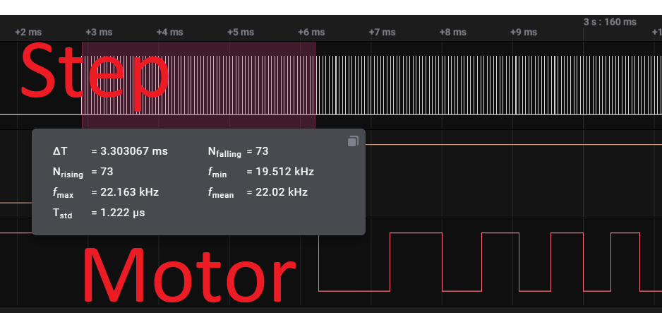
- I'm seeing about 70 step pulses at the beginning of a move before the motor shaft moves. (That's 2.x step at 0.9 degrees-per-step) It seems like this is acceptable for 3D printing.
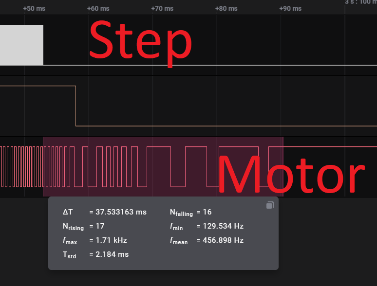
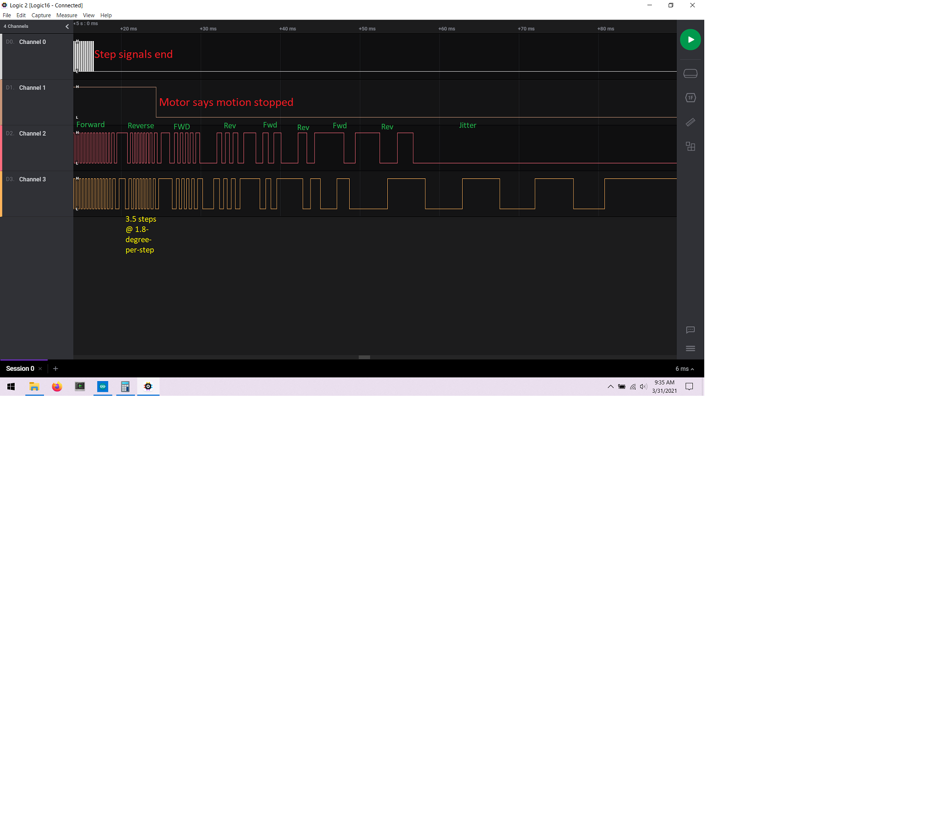
- I see in the neighborhood of 16 encoder pulses at the end of a move after the step signals complete before the motor stops. This is about 12 degrees (13 steps) which seems like a LOT and I would think would cause printing problems.
I'll update so I can capture both encoder signals to see if the motor is oscillating around at the end of a move or if it's actually decelerating and continuing to move in the same direction.
As it stands, I'm not sure these will work for printer drivers (yet)
Setup:

Beginning of move:
End of move:
-
@Toastinator I built a better motor-to-encoder mount and have takes some more data and I'd like some expert thinking about this.
I see when the motor comes to a stop that it takes tens of milliseconds after the step signals end before the motor actually stops moving.
And the motor does a bit of a "Boing" oscillating back-and-forth a few times as it comes to a stop.
I think all these are from the closed-loop control part of the system, not from the stepper motor itself because the magnitude of the "Boing" is greater than 1 step.
Anyway, I'm thinking that this amount of movement and delay-after-stepping-stops won't be visible in a print, but I'm not sure.
ALSO, this is a raw motor connected to an encoder so there's no real mechanical load on the motor at all and it will behave very differently in a real machine.
Will it boing more or less in a real machine? That's impossible to know.
My next step is to connect it to the Duet2/Ethernet and see what it does when asked to move based on Gcode and all the motion-control stuff in RRF.

-
@alankilian
thumbs up for your setup!
But I still don't dig your encoder-coupler. Sure the encoder has almost zero friction/stiction but to me it seems the cosed loop circuit has a PID algorhythm and the flexing? shrinktube introduces the 'boing'.
I'd put a load to the motor, the PID (if there is any) will be less jumpy then. -
@o_lampe That blue encoder is not involved in the closed-loop control.
It's just for monitoring the motor shaft angle.
All the closed-loopidness is done inside the motor itself.I could stick something into the gap and press on the motor shaft a little to add damping and see if it changes the situation.
Of course, a REAL mechanical system will COMPLETELY change the dynamics because there will be actual friction/damping and inertial loads.
What I'm interested in now is will it make any visible defects if:
- It takes 25 milliseconds after the last STEP before motion stops
- If the stop position oscillates like +/- 4 degrees of motor shaft at the target setpoint.
I've got a Delta, so I don't know what a "normal" pully-degrees-per-effector-mm ratio is for a printer.
SeemeCNC Rostock Max V3 converted to V3.2 with a Duet2 Ethernet Firmware 3.2 and SE300
-
@alankilian said in Closed Loop Motor Setup:
That blue encoder is not involved in the closed-loop control.
The encoder has a rotormass, so there is inertia and the shrinktube 'stores' energy, too. That was what I meant.
-
@alankilian Really Great Job, Hope someone Can Shed some light on what's going on here
Happy Easter Everyone!
-
Seems like the "boing" could be tuned out or maybe it is tuned and the lack of load is causing it to do that because of current settings (I didnt catch if it is tunable)
-
I connected your motor to the Duet2/Ethernet this morning and made some moves at different speeds and everything went as expected.
; Drives
M569 P0 S1                                              ; physical drive 0 goes forwards
M569 P1 S1                                              ; physical drive 1 goes forwards
M569 P2 S1                                              ; physical drive 2 goes forwards
M569 P3 S1                                              ; physical drive 3 goes forwards
M569 P5 S1 T4:4:4:4                                              ; physical drive 5 goes forwards
M584 X0 Y1 Z2 E3 U5                                     ; set drive mapping
M350 X16 Y16 Z16 E16 U16 I1                             ; configure microstepping with interpolation
M92 X100.00 Y100.00 Z100.00 U100.00 E91.00                      ; set steps per mm
M566 X1200.00 Y1200.00 Z1200.00 U1200 E1200.00                ; set maximum instantaneous speed changes (mm/min)
M203 X18000.00 Y18000.00 Z18000.00 U18000E1200.00             ; set maximum speeds (mm/min)
M201 X1000.00 Y1000.00 Z1000.00 U1000E1000.00                ; set accelerations (mm/s^2)
M906 X1000 Y1000 Z1000 E800 U1000I30                         ; set motor currents (mA) and motor idle factor in per cent
g91 g1 u100 H2 f12000 g1 u100 H2 f6000 g1 u100 H2 f3000 g1 u100 H2 f1500 g1 u50 H2 f800 g1 u50 H2 f400 g1 u25 H2 f200You mentioned that you were unable to "control the speed" and I have no problem moving at different speeds, so I think we should look at that. It might be the core of your problems with getting two axis synchronized.
I haven't compared my config.g with yours yet.
I'll take a look at that later today.The thing I don't know about is the toolboard stuff.
@dc42 Wasn't there something that limited the step-rate across the CAN bus? Could that have caused his inability to change the speed of the motor? -
Yes, The Speed Did Not Change, Could it have something to do with the Duet 3 Expansion 1XD Board Drivers Or The Step Rate Across The CAN Like you mentioned.
Also, Did you see any Delays Between 2 Different Axis Movements? To See if Triggers are required to Continue only after moves are completed?
-
@toastinator I only hooked up one motor for this test.
I'll hook another and try some different moves and let you know.
After that, I'll send them back to you along with a logic analyzer so we can monitor the exact step signals coming from your Duet to the motors and see if we can determine what the problem is for you.
Are you interested in hooking up the logic analyzer and doing experiments using your Duet?
As far as I can tell, these motors should "just work" when connected to a Duet.
-
@alankilian Ok Sounds Good!
I Don't Mind Doing Experiments, I Should Let you know that Im in the Middle of using this Printer with Normal Steppers to Print out parts to Build a Voron V2.4 3D Printer. Will Slap those Motors back on when Finished with the ABS Parts. Ill Be Printing for At least another Week
While Also Experimenting with a Filastruder to Make my Own PEEK and PEI Filament. Im Buried in Projects!
-
@toastinator I couldn't get my super-old USBee logic probe to work with Windows 10 (No big surprise) so I'm going to send you my Saleae Logic16 probe instead.
When it gets there you should be able to hook the two motors up to unused axes (like U and V) and then do some G1 U10 V10 F600 (or whatever) moves and look at the pulleys and see if they start and stop at about the same time for various moves. Adding a bit of tape with a line on it will tell us you've got the steps-per-mm and microstepping right.
You can also capture the step signals coming out of your board to see if THEY start and stop at the expected times.
Driving these from both an Ardiono and a Duet2 expension connector made them work as I expect and they should be perfectly usable on a 3D printer.
(I'm still unconvinced that a 3D printer benefits from slosed-loop stepper motors, but I'm not the one trying this, so I'm willing to get you going if I can.)
I'll send the stuff back next week. You can return the logic16 when we've exhausted our experiments.
-
@toastinator & @alankilian thank you so much for bringing this topic to its max and @alankilian thank you for investing your time analyzing theses motors. I have exact same motors for a Corexy printer setup and unfortunately the print quality is awful I’m using duet Ethernet and duex 5 the motors are connected via ConnLCD mapped to driver #10 and 11. T parameter set at 5.0 for all pulses which is the max of 200khz. The motors moves correctly and very accurate in terms of steps=Distance homes correctly sometimes I get errors when I’m homing where the X-axis stops few mm before touching the endStop here’s some pics of the print quality.


I’m not sure why it’s causing this inconsistency with print maybe because conn lcd only provide 3.3v and the motor driver requires 5V minimum. Or maybe timing not very responsive. I’m not sure. Sorry I didn’t mean to jump in to your conversation but I thought it might help share it. Thank you
-
@moe-adams9093 Oh man, that really is horrible.
- What do you have your switches set to?
- Have you adjusted any of the settings via the serial-port interface and the Windows software?
As I said before, for this kind of 3D printing I don't see where a closed-loop stepper motor would improve print quality.
I get that if the head bangs into something that you won't layer-shift like an open-loop system, but it seems like closing the loop the way they are doing is more for high-speed speed-control improvements and not low-speed position-control improvements.
-
@alankilian so I have them set on 6400 plus/rev 160steps assigned in config.g set on 25ms for better noise quality. I didn’t use the computer software to change settings so I did my research and kept everything on default. I got these motors because I want a high speed print something to reach 400mm per second. I don’t have whole lot of knowledge yet on testing closed loop so I’m still learning. So right now I’m modifying my motion system is heavy and I’m trying to make it very light so I can achieve a better and smoother motion. Also I ordered a logic level shifter to make signal 5V from conn lcd 3.3 v that might help and I’m not sure yet. But I think these motors are overkill for a 3d printer because let’s assume the nozzle hits the print while it’s printing the belt will 80% likely to skip the pulley teeth before the encoder realize it skipped a steps they are very strong. So I’m still doing my research. What software did you use to connect them via pc? I contacted the seller to see if they can provide the software and never got any response.
-
@moe-adams9093 I got the software from @Toastinator I'm not sure I can share it, so contact him and see if he'll send you a link.
I just connected the Duet to the motor and it worked fine. Level translators shold be even better and remove any doubt about signalling.
(Actually, I connected the Duet to one end of a 2-meter VGA cable and the motor to the other end because I couldn't find and decent multistrand wire.)
-
@alankilian I contacted jss motors last night and they just sent me the zipfile for the software. Did you use any RS232 breakout board to connect via USB and man there’s lots of settings in here to play with. So let’s say if I change anything what will I set the dip switch I’m assuming all set to default because it’s going to over write the default settings maybe?. Thank you
-
@moe-adams9093 This motor uses "real" RS232 signal levels, so you do need a USB-to RS232 adapter. Most any will work.
You use the DIP switches to set some of the settings and the software to set others. So the DIP switch settings are still important.
SeemeCNC Rostock Max V3 converted to V3.2 with a Duet2 Ethernet Firmware 3.2 and SE300
-
@toastinator said in Closed Loop Motor Setup:
While Also Experimenting with a Filastruder to Make my Own PEEK and PEI Filament. Im Buried in Projects!
Try PEKK instead of PEEK. Better than PEEK in some respects and waaaay easier to print
Duet controlled Jet Lathe, scratch built micro mill and 3d printer. 1992 Haas VF2 VMC retrofit