Have you ever observed this layer thickness problem?
-
@drmaestro Personally, I don't buy the backlash theory because it's difficult to imagine how that could happen on a CoreXY - a Cartesian maybe but not a CoreXY.
Are the external perimeters always laid down first/last or does that vary? It reminds me of a similar effect I've seen when printing a solid top layer using a mixing hot end. In this case, it shows as a variation in colour depending on whether the 45 degree infill is being laid down from left to right or if there is a change in direction from right to left. The colour of the mixed extruded filament will vary depending on which side of the "bead" is supported.
So in the case of an external perimeter, the thickness of the bead will depend on whether there is a previous bead of filament that the new bead butts up against or not. i.e. if the external perimeter is done before the infill, then it's like;y to be a different thickness than if it's done after the infill. Could that be what's happening?
-
@alankilian i used to have a V2 and always seen that problem. The real problem (for Delta) is that is really difficult to make the effector to stay flat with the bed surface independently from the direction it is travelling. If you look close when printing, the effector would probably tilt a little bit when switching direction. Also a very little tilt could lead to this because the nozzle is far from the center of the rotation.
So this shows up when a line is lay down in +X direction and the next one in -X direction from example.
I left delta because they need to be really rigid to work properly and seemecnc's one are not so good at this (mine was made in wood so it was the worst case). -
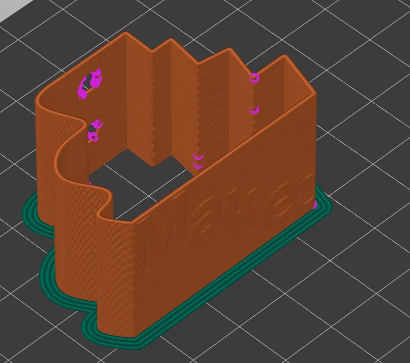
@deckingman Maybe. A problem with this object (with 0.8 mm thick wall) is that the slicer doesn't really consider it as an object with an internal and external perimeter. The fact that it is making a horseshoe turn makes the line a closed single loop, so a single line in fact, even though there should be two lines. I've loaded the 0.8 mm and 1 mm objects, and also another object with thicker walls to Prusa Slicer. Here's how they look at thelevel of a hole:

The object on the bottom has external perimeters (orange) and internal perimeters (yellow). The object on top and right is the 0.8 mm object and it only has orange perimeters, so only external. The obejct on top left is the 1 mm object and while it has some gap fill between the perimeters, they still are external perimeters according to the color. Maybe that's the problem?
So in this object's case, the object starts printing form the external line (even though internal perimeters first is selected) from a very close location to the hole, goes a few cm towards the hole, makes its 180 degree turn and goes to the internal line, finishes that line at the other end of the hole and makes its second turn to finish the external line (I have chosen aligned seems so it starts from very similar locations). Even if I chose to print with the external perimeters first option, it still performs the same trajectory (probably as a result of not having an internal perimeter) .
-
@drmaestro Another possibility is that although I don't buy the backlash in the gantry/carriage theory, is your hot end solidly mounted? Does it flex like a groove mounted V6?
-
@deckingman It used to flex a little bit when I was using groove mount on plastic version of my X car. So, I've bought an adapter (this one https://www.aliexpress.com/item/32890582038.html?spm=a2g0o.productlist.0.0.727965c11yqaj9&algo_pvid=a5da6614-4232-4c0e-ba6f-5602b69cf33f&algo_expid=a5da6614-4232-4c0e-ba6f-5602b69cf33f-14&btsid=0b0a555516211823561961742eb46d&ws_ab_test=searchweb0_0,searchweb201602_,searchweb201603_) , so it is metal on metal now. There was a very slight movement due to tolerances (or bad manufacturing), so I designed a plastic part that plugs to it and ifxes it in place.
There is no movement if you try to move the hotend (of course it is still bolted to plastic and the plastic can flex but I don't imagine it would flex during routine printer movements).
-
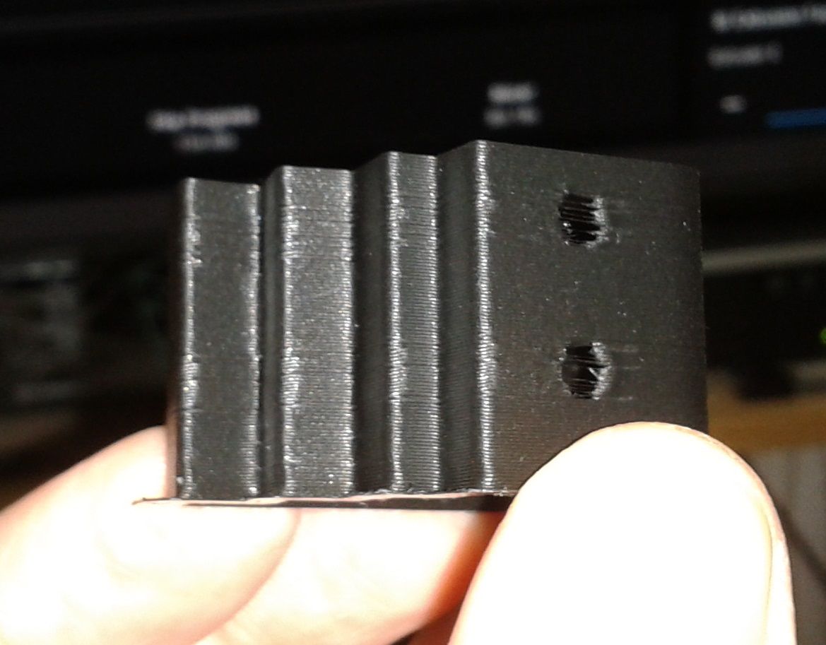
I also did some test prints:
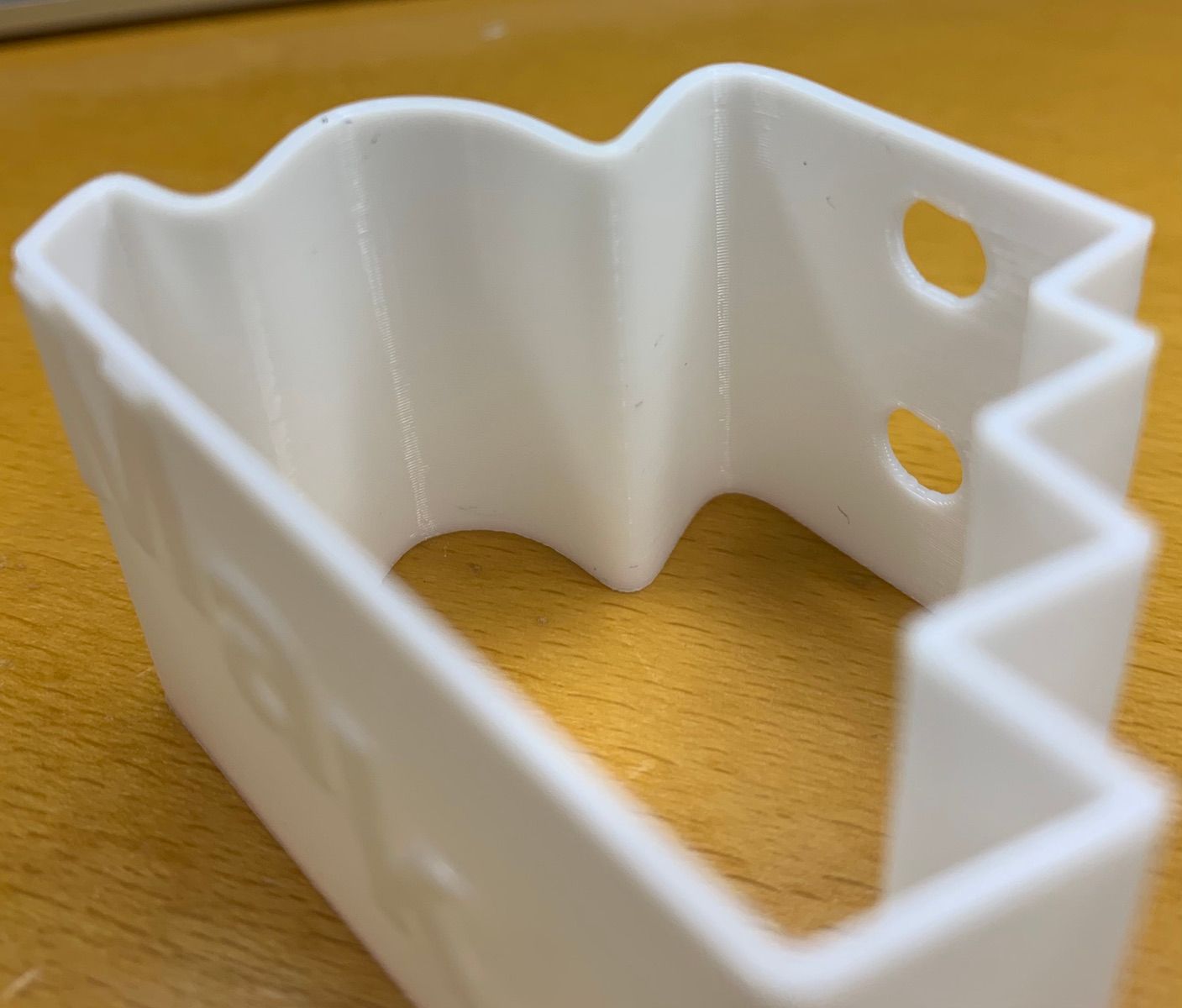
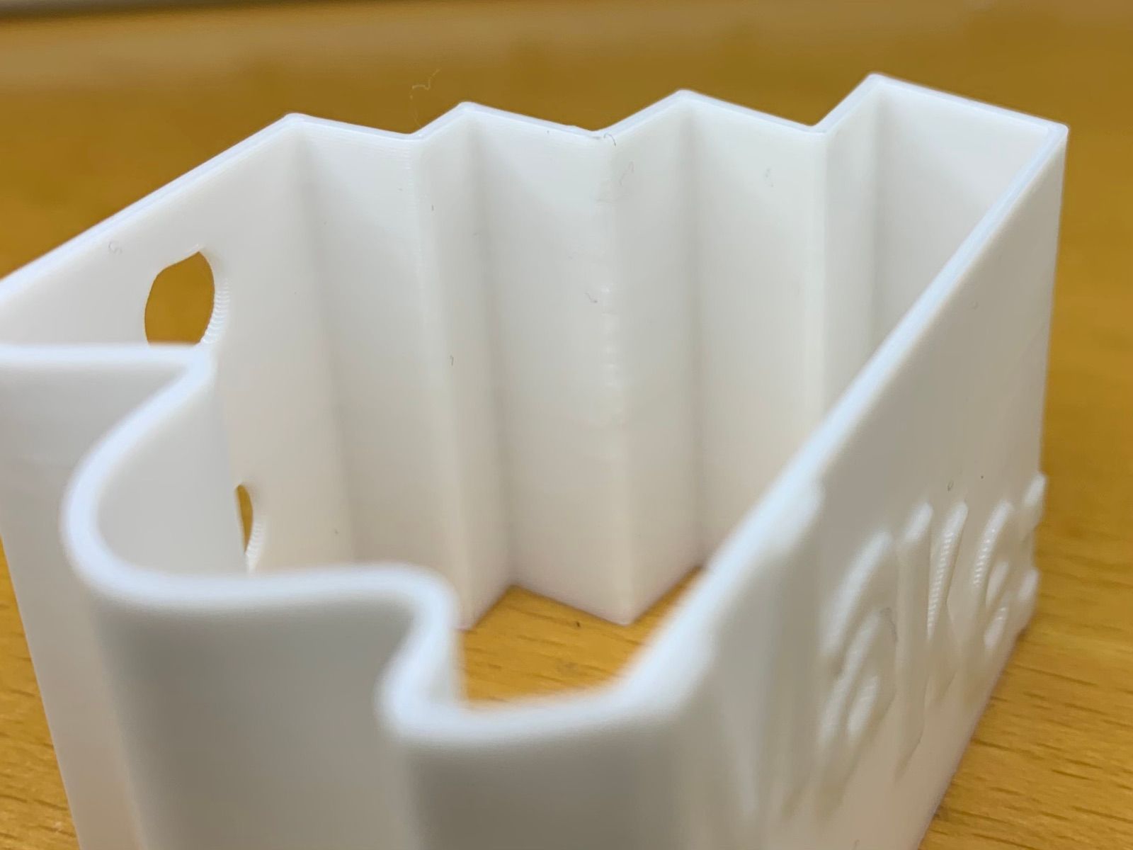
I played around with lightning and tried to establish a "bad angle" to see all the inconsistencies of FDM but it's hard to capture.
-
@argo That's very good. It means I have to go back to my printer and look for more mechanical issues....
-
@drmaestro said in Have you ever observed this layer thickness problem?:
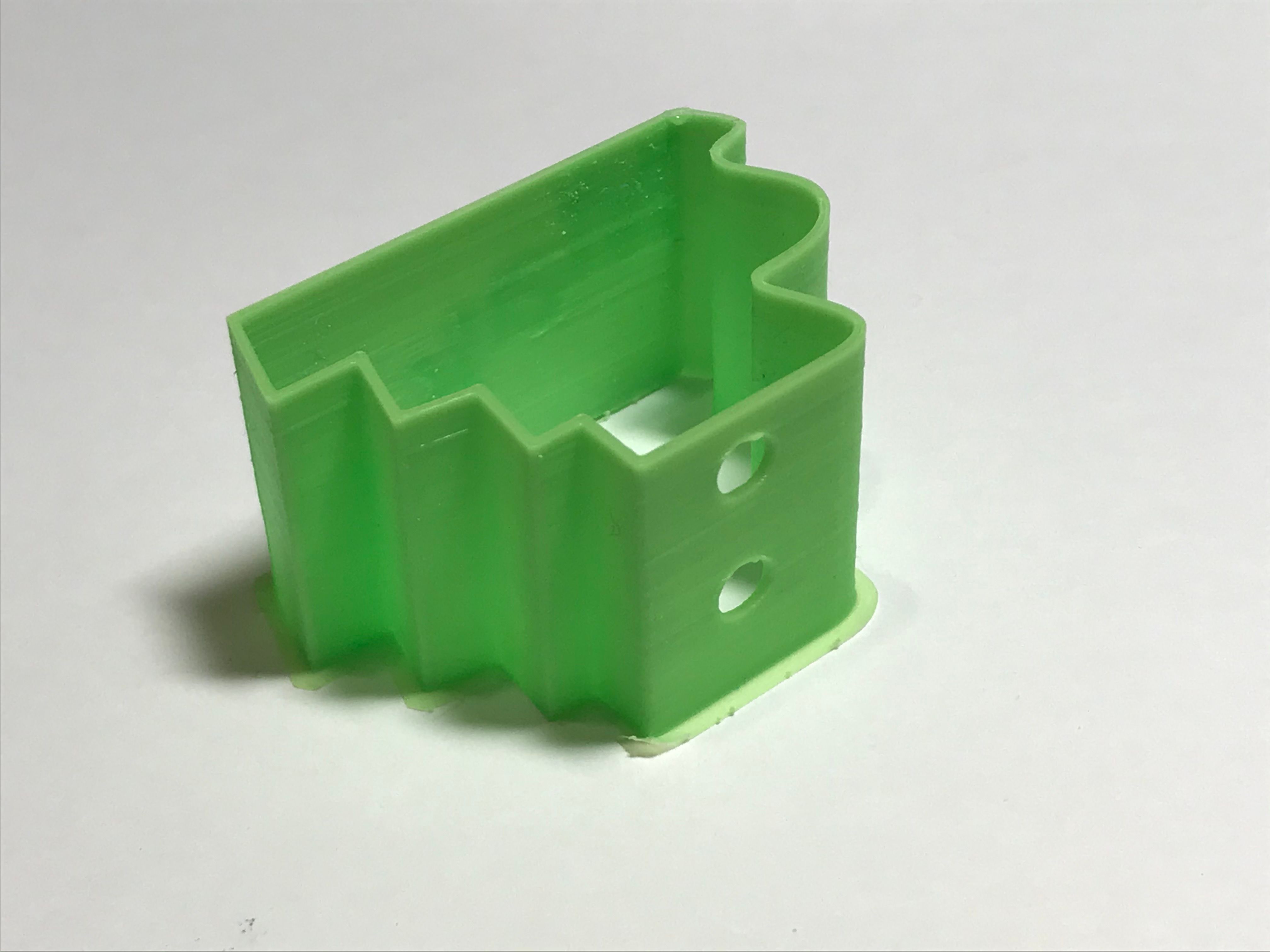
The wall thickness changes depending on the features on the object, so when there is a hole, the wall is thicker
Your picture in RepRap forum from 2017 show no signs of thicker walls, but an offset. I agree with @deckingman about the inner/outer perimeter first theory. I printed 'outer first' and saw the shift towards the outer face. (when direction changes)
link textYour 0.8 slice is different than mine. I only see one perimeter and retractions.
But the print showed a loss of quality all around the part, where there's a gap/hole. It can't be explained by bad retraction settings alone or backlash-offset.
If you see different thickness now it's probably another problem? Maybe related to scaling up the part?
-
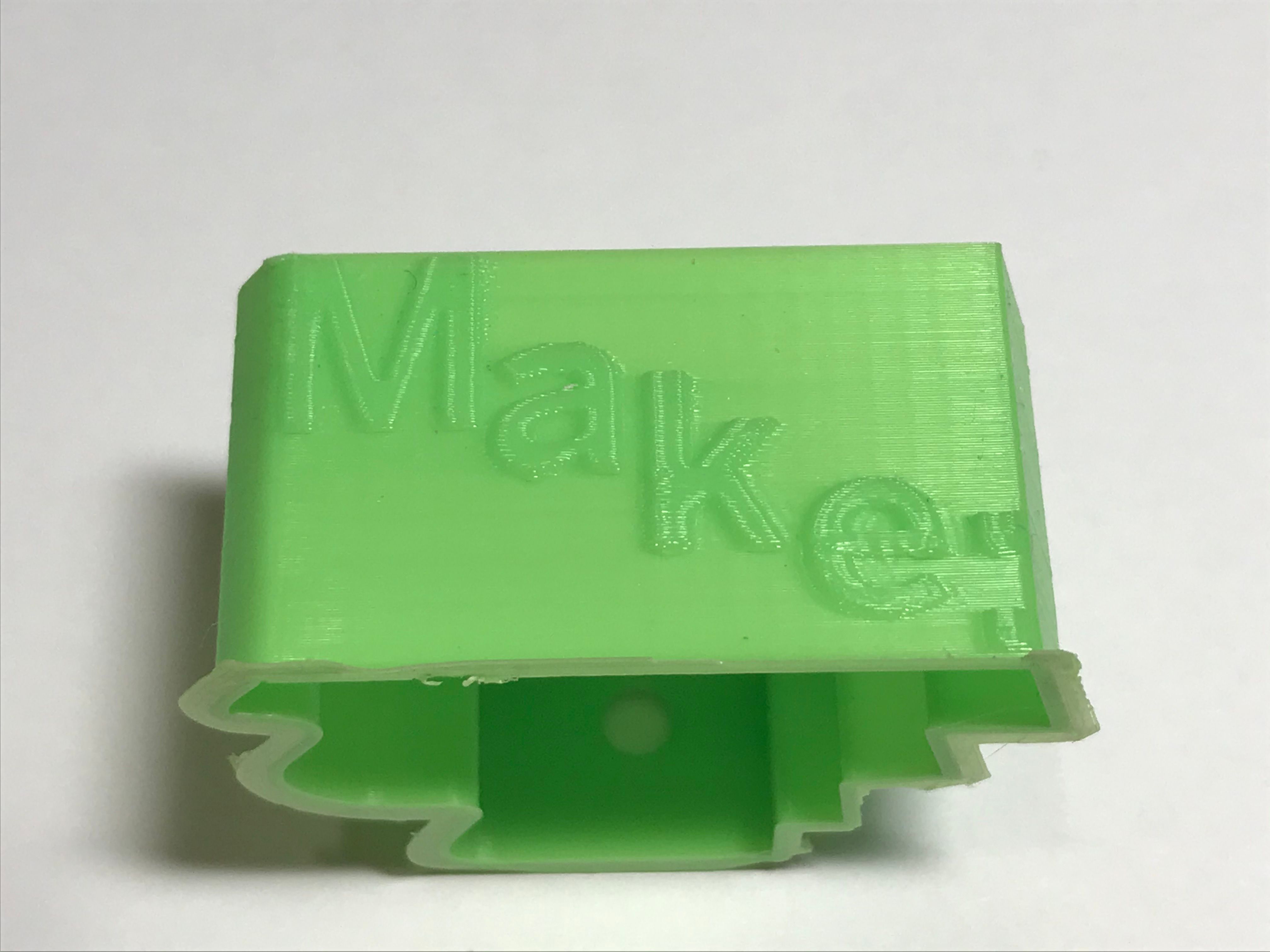
@dc42 @o_lampe @deckingman I've rebuilt the Y carriage, removed the twist that I used for smooth side of the belt on smooth idler, replaced the idler with a toothed one, retensioned. Here's a comparison of the object post-modifications:

It turns out you were right, there should be something related to backlash on my setup. While I still have the artefacts, thery are not as prominent as they were previously. I may still have some ğrpblem on the X axis, which I'll also replace with another solution.
-
I asked user @Hiroaki to print one on his RRF2.x printers.
-
The problem has a distinctly "hysteresis" feel about it. That is to say, that travelling in one direction does not result in the same path as movement in the other direction. Belt tension would be an easy culprit for this problem, but as such, it's the first one to be resolved.
Here's what I suggest. Isolate travel direction as the problem - Print a simple thin walled square (50x50 should do), go CW for 10-20 layers, then CCW for 10-20 layers. If hysteresis is the problem you should get the same bands appearing with direction change. I imagine you'll need to generate this code manually to control the travel direction.
If this occurs, you'll need to look for anything that gives you some uncontrolled movement - it could be as subtle as flexibility in the hot end, or a pulley (or many pulleys in the case of a CoreXY) that move slightly on their shaft. Remember you're looking for problems that add up to a total of a fraction of a line width - so perhaps 0.1mm or less.
Best of luck.