SSR defective again - Which method of Thermal Fuse
-
The SSR was not super hot while operating. The chosen wires are thick enough (6,0 mm²)
Also I've installed an Always-On-Fan that is permantly cooling down the SSR and the cooling body on which the SSR is mounted.The Manufacturer of the SSR is called "pohltechnic"
website: www.pohltechnic.com
My SSR is this one:
https://www.pohltechnik.com/de/ssr-relais/ssr-lastschaltung-dc/gleichstrom-solid-state-relais-dc-dc-steuerspannung-3-32v-dc-80-aBed configuration (I hope I got it right, you want me to post the part "Heaters" from my config.g file?
; Heaters
M308 S0 P"bedtemp" Y"thermistor" T100000 B3950 ; configure sensor 0 as thermistor on pin bedtemp
M950 H0 C"bedheat" T0 ; create bed heater output on bedheat and map it to sensor 0
M307 H0 B0 S1.00 ; disable bang-bang mode for the bed heater and set PWM limit
M140 H0 ; map heated bed to heater 0
M143 H0 S120 ; set temperature limit for heater 0 to 120C
M307 H0 R0.085 C1598.722:1598.722 D40.63 S1.00 V24.3 B0 ; set the process parameters for heater 0
M308 S1 P"e0temp" Y"thermistor" T500000 B4723 C1.19622e-7 ; configure sensor 1 as thermistor on pin e0temp
M950 H1 C"e0heat" T1 ; create nozzle heater output on e0heat and map it to sensor 1
M307 H1 B0 S1.00 ; disable bang-bang mode for heater and set PWM limit
M143 H1 S350 ; set temperature limit for heater 1 to 350C -
@heinrich-platau The SSR says you should use a maximum of 5 Hz input signal.
The default PWM frequency is 500 Hz.
Maybe next time use:
; create bed heater output on bedheat and map it to sensor 0
; Set maximum PWM frequency to 1 Hz for the SSR
M950 H0 C"bedheat"  Q1 T0
I don't REALLY see why using a much higher than recommended PWM frequency would cause a problem, but I really don't read German very well.
-
Hello,
An SSR is normally not able to use PWM at all, it should be used as a switch on/off only.
The 5Hz frequency means that it should not be switched on/off more that 5 times per second.
It is a replacement of a mechanical relay.
Who would try to use PWM with a mechanical relay?Regards Mark,
-
@alankilian said in SSR defective again - Which method of Thermal Fuse:
I don't REALLY see why using a much higher than recommended PWM frequency would cause a problem, but I really don't read German very well.
Because typically they cannot switch that fast.
If the specs say 5 Hz then use 5 Hz.
The ones I have work fine at 10 Hz.
Frederick
-
Maybe this will be useful:
https://omronfs.omron.com/en_US/ecb/products/pdf/precautions_ssr.pdf
If you're switching AC to a bed heater, and the line frequency is 60Hz, there's no reason to use an input switching frequency any higher than that. Bed heaters are heating relatively large masses that are slow to respond to input. That's another reason not to switch fast, and even 60 Hz is more than needed.
I suspect the problem with fast switching is that the SSR takes time to actually go from off to on and on to off. During that period it is generating heat. If you switch really fast, you're creating a lot more of those on-off cycles than needed and causing the SSR to heat up. In my experience, driving a 750W line powered heater with an SSR at about 10Hz, the SSR never even gets warm with or without a heatsink. It maintains a constant bed temperature +/- 0.1C just fine.
-
If I've understood zero-crossing SSR operation correctly, there's a very good reason to have your control PWM at much lower frequency than the mains voltage.
I think the SSR only switches the load on when the input control signal is on AND the input line supply voltage is at (or very near) 0V. So if your control PWM is fast, it will signal on and if the 50Hz or 60Hz mains supply doesn't get to 0V before the control signal goes off again, that PWM cycle is missed entirely - the SSR stays off.
Further, you'll never see a good output voltage because the SSR switches off as soon as the control signal goes off, so you'll only ever get a low-value slice of the sine wave at the output.
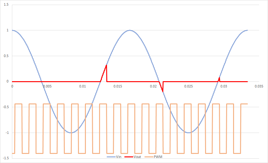
So if your signal is running at 500Hz, and your supply line is at 60Hz, something like three quarters of your control signals will be ignored and the remaining one will be distorted (never peaking above about a third of your line voltage peak) - with a 50% PWM you'll get output on something like 4% of the time, and the power output will be under 1% on average (a small fraction of what you wanted) (assuming power out is proportional to the integration of the voltage out squared).
This is 60Hz mains, 500Hz 50% PWM, perfect SSR, and the power output is 0.2% of full:

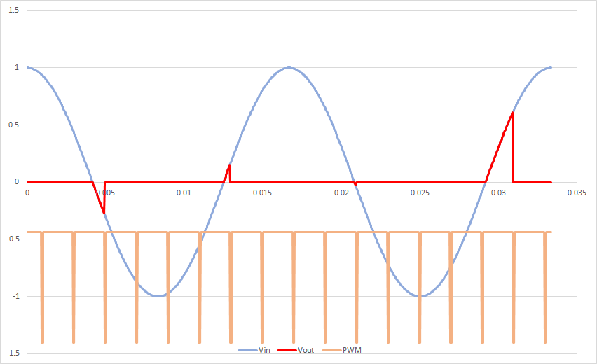
If control frequency is much higher than mains frequency, you effectively only get on-off control: any time the PWM signal is at less than100% duty you get near-zero output - less than 3% or so anyway - this is 95% duty PWM, output is only on 9% of the time and only 1.5% of full power out:

Having said which, if 500Hz is still within the spec for the SSR, I don't see why this would damage the SSR, it just means the achieved level of control is rubbish (effectively you've lost proportional control and are only on bang-bang).
-
@achrn I think that a lot of the cheapo SSRs that people use for bed power switching don't have zero crossing detectors.
-
@mrehorstdmd Actually, I've just re-examined the datasheet for what I have used in my most recent build and it specifies that both turn-on and turn-off is at zero crossing. (Panasonic SSRs).
In that case, my graphs are also wrong (but in a differnet way) - it would mean each half-cycle on the mains has an essentially random chance of being found on the output, where the chance is in proportion to the PWM duty cycle.
Agreed that if you use a SSR without zero-crossing switching these behaviours are not relevant.
I run my mains bed SSR at 5Hz (which I think I picked so there were 20 half-waves in each PWM cycle, so my error would be no more than 5%, which seemed close enough). The data sheet doesn't specify a limit on the control frequency, but does note that operate and release times are 'Max. 1/2 cycle of voltage sine wave +1 ms'.
-
-
@achrn I enjoyed your analysis of zero-crossing SSRs and an AC bed heater. Thanks you for that.
This guy is actually talking about a DC bed heater and a DC SSR, so your analysis does not apply to this situation.
-
Thank you very much for evry answer. I think first of all I should check the PWM Frequency (Q-Parameter) and change it to 5 Hz as the data sheet says.
I've already ordered a 230V heating bed. So my amps will be much lower. Finally I will install a bimetal switch (130°C) as a thermal fuse to guarantee fire safety...
But I am very thankful for the tip about the PWM Frequency... So far no one could give me an explanation why the SSR got defective.
-
-
Hey, probably shouldn't need to remind anyone, but when implementing high-Voltage wiring, to use extra safe wiring methods. heat-shrink where possible, Insulate all exposed current carrying metals, enclose it if possible, definently fuse it, etc. And be sure to mount the SSR on a heatsink, preferrably finned. In addition to one not desiring to burn-down one's house, it is also unpleasant to electrocute one's pets, children, wife and-or self!! ;-}
Rotsa Ruck!
3mm
-
@3mm Also fuse low , if the maximum wattage of your 3d printer is 500 watts remove the 13 amp fuse which will be in the fuse by default and replace with a 3 or 5 amp fuse.
Use a ELCB / RCCB where possible . -
Hi Guys, I've updated my setup- So now I'm running a 230V Heating Bed. I've also added the bimetal switch and finally put my heating parameter (PWM-Frequency) to Q5 (5Hz).
After running autotuning I got this message:

WARNING: Heater behaviour was not consistent during tuning.
Is this a problem? Or is this warning caused by the lower frequency ?
I noticed the the temperatur curve of the heating bed was much more wavey than the old one wich 500Hz, which for me is logical.
-
@heinrich-platau Can you post a link to the data sheet for the SSR you are using now?
Since it's an AC SSR, you might be able to run a higher PWM frequency depending on the SSR.
-
Here's the data sheet
Seems to be no difference. All SSRs are 5Hz
-
@heinrich-platau I see that as well.
I guess I would try those settings and run it up to the temperature you want to print at and see how stable it is.
Or maybe let it cool COMPLETELY to room temperature and tune again?
(I don't have much knowledge of the bed tuning algorithm, I'm sorry to say.)
-
@heinrich-platau I had also this message after the first tuning. Try to run the tuning again.