What tricks have you found to reduce seam bumps?
-
@jens55
Sorry , where I mentioned the first layer?
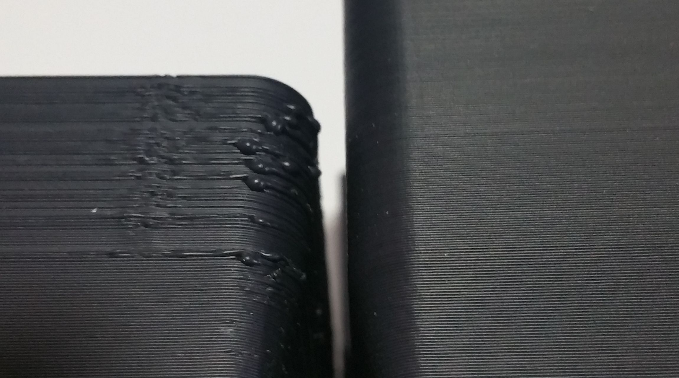
In the first layer (the top one), lines are squished when they change directions but are spaced in the middle. Also this is not regular. (apart that you have top/bottom thickness set to zero and a lower infill than 100% - are you using zig-zag infill?).
You can see the strange overlap (in the seam) even at the first layer when lines change. There is too much material in the seam that go till the inside of the part.
I mentioned the last layer (the one at the bottom of the picture) as wave also if it is visible sins the second layer (from the top).
On the right side the print seems pretty good. But there are some adjustment to make for remove those last artifacts. (overlap and maybe wave). -
-
@giostark, the wave is part of the printer frame oscillations in my opinion and I am not expecting to solve that issue with this ptinter.
The squishing of the lines at the edges is normal as the lines are connected and there is extra material deposited. The part of the first layer that isn't normal is that there are alternating wide and narrow spaces between the lines of material laid down. This has been an issue since day one though. I could also adjust the first layer to give me less empty space but overall and for this printer this is a good print.
How would you suggest to go about reducing the material put into the seam? -
Never standstill. Be quicker than the ooze. Quick retraction, quick z moves, quick travel moves, optimized jerk, and jerk policy 1 (M566 P1) to allow jerk between print and non print moves. At that point pressure advance. Inner walls > outer walls > infill helps to hide them a bit as well.
-
@jens55
ok about what you say for the oscillations.
For the deposit I'll change also there some settings but there are too much variables for allow me to say something.
Your blobs are not just blobs for too much deposit , they have also overlap.
I'm not skilled enough for tell you to change one parameter in the slicer that will solve the issue.
For my self I tried to zero more or less all the parameter in Cura and tried to print the cube, than after the inspection of the printed part, I raised or lowered some setting value and reprint. (is enough print just some layers , not the entire cube walls , ugly stuff will be soon visible and you can stop the print)
The mess is that what is right for layer height 0.3 is not valid for 0.1. (at least on my printer).
Or what is valid for one speed is not good for faster speed.
Hope the bunch of suggestion and impression will help you to understand what happen at your printer. -
@jens55
An example of what I'm saying about the attempts.
Those two cube have ALL the setting equal apart one , the "line width". With the nozzle 0.6 Cura produce 3 lines for the 2mm wall thickness. Inner and outer wall have regular width BUT the inner line is thicker. Cura is able to produce the part on the left. Horrendous as you can see.
Moving the line with to 0.5 (always with the 0.6 nozzle) Cura generate 4 lines of 0.5 and come printed the part on the right. Almost perfect.
So , to say exactly what to do in your case is complicated. But I would be happy to help if possible.

-
@giostark, wow, I would have never suspected that .... and for that matter I don't understand it ... but there it is in black and white.
With a line width of 0.6 mm and three lines that is a total of 1.8 mm so Cura 'fills out' the missing 0.2 mm on the inner line. Seems perfectly normal and I would likely spend the next month changing Cura settings to figure out why it does that. There are some settings for filling and thin lines and the like. That still doesn't change my utter disbelief of what is happening ....
I tend to run line widths of nozzle diameter or slightly larger. Under normal circumstances, with a 0.6 mm nozzle I would likely run 0.7 mm line width. I presume that would result in an inner, an outer and a thin filler line in the middle but that is where this kind of finish would actually make sense. -
@jens55
line width and part strength go together. If you want strong parts go for wider_than_nozzle width, but Not for outer wall.it takes a whole spool of filament to dial in a new printer is what I've learned. Same for a new slicer, probably...
-
@giostark what happens if you set linewidth to 0.65?
-
@oliof
More or less same ugly stuff. Not being a multiply of the wall thickness happens blobs and/or gaps. Cura is an amazing program but have several limitation and is necessary to know them for not lose ages in attempts.
Probably there are way to compensate all those things but still I have not put in enough time for make the things better.
Ex:
Same settings apart 2 of them.
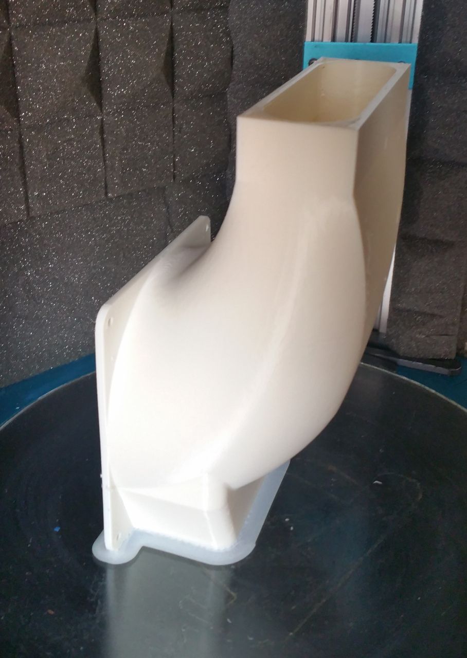
This conveyor printed at 0.25 layer height and 0.5 (on 0.6 nozzle) come good enough apart the damn seams (I didn't had the right settings because I never printed this part before)
This other part instead come print at 0.3 layer height and 0.65 line width and ugly staff happen (I tried this for speed up the print) .
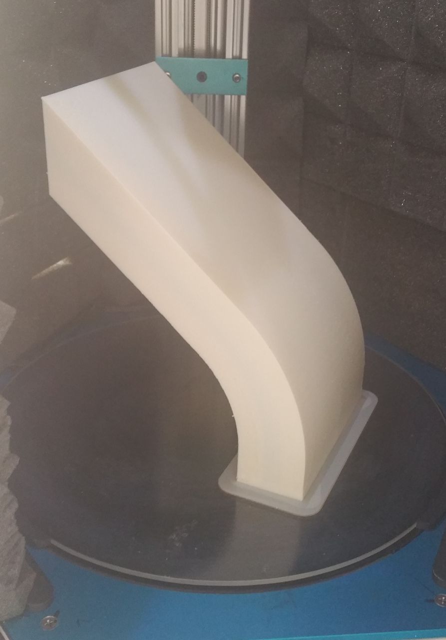
Both the part I designed have 4mm wall thickness. So now I can expect that some ugly stuff can happen if the wall are not multiply of the line witdh. Maybe if I would be able to fix the walls will come ugly the infill haha. Such a trap !
-
@giostark ugly infill is most often not an issue as long as it stays in place and doesn't push onto the walls.
-
Ultimaker does provide a decent amount of guidance on what their (basic) settings do. https://support.ultimaker.com/hc/en-us/sections/360003548619-Print-settings
And there is a plugin that gives even more info as popups within the app.
Narrow walls have always been one of it's biggest weaknesses. They do suggest altering the line width such that an even number of lines will fit within the wall. It does a terrible job on it's own. If you don't wnat to set a smaller or larger line width for the entire part you can use modifier meshes to change it for only the sections of the model that require it, but that takes some additional setup.
Slic3r has much better gap fill detection. Hopefully the new Cura slicing engine with variable line width will make this a non-issue soon.
-
many times seam bump is generated at the start of the loop .
also there is no retraction at every loop end (unless you force it)
in those cases i use layer start script that retracts very little at the start of the loop (outer perimeters first) -
@hackinistrator Most slicers would have a retract on layer change or retract on travels setting as well to facilitate that.